Write an application that interfaces with an input &/or output device that you made.
Introduction
This week I combined output and input from the ATtiny 45 micro controller.
The result(Photoresistor filter level) was read from the serial port using the FDTI cable,
and the data was exported to a Excel csv file for further investigation if desired.
For the assignment I used my modification of Neil's hello.light.45 board (See week 12).
Based on the lack of electronic components, I design the hello board so I could add components (in/output devices) to it using a breadboard.
(See Figure 1.)
This week I put focus on the programming. I notices that the Arduino IDE (still) don't work for the serial reading
of the FDTI cable. Based on Neil C-code for the hello.light.45 board I studied how to turn a ATtiny45 pin to do serial output.
In the c-code the PB2 pin serial value was based on the input value on PB3 pin that was connected to the photoresistor.
In the c-code I put a constrain for the PB4 pin, so if the numerical value from the serial port (PB2 pin) is high (>200)
the PB4 pin voltage is HIGH (otherwise it is LOW). A LED that was connected to the PB4 pin.
If no light reaches the photoresistor ,the calculated filter level from the PB2 pin was high, resulting in a HIGH value on
the PB4 pin, and the LED was turn on.
Problems
Connecting wires to the board could results in shorting. That is what happens for me, I "killed" the ATtiny45,
but I managed re-soldering the board and put a new ATtiny45 on it.
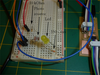
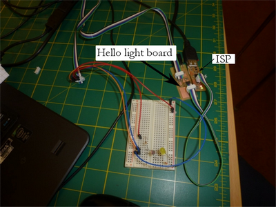
Figure 1. The photo resistor and the led connected to my hello.light.45 board through a bread board.
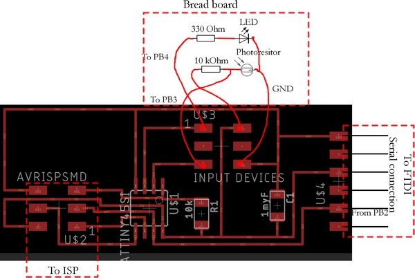
Left: Closer view. Right: Overview image.Figure 2. Skematic of the photo resistor and the led, connected to my hello.light.45 board.
Here is a movie that shows three states of the photoreststor-led system (Movie).
In laboratory light, photoresistor filter value low, the LED is off
Cover just the photoresistor, filter valure high, the LED is on
Cover the system, the photoresistor "see" only the LED, and the system will start an on-off sequence(Flashing LED)
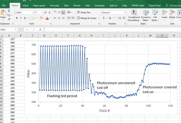
Figure 3. Graph and data from the Excel file exported by the Python script
show the different level of the filter value from the photo resistor.
Programming
Modification of Neil's C-code to control the PB4 pin(LED) based on the value of "filter".