Debugging
Note from the lecture by Mr.Yamamoto (skilled electrician) at Fablab Kamakura.
Findout causes
- software?
- application file?
- tool?
- timing?
- protocol?
- hardware?
- circuit design?
- board?
- parts? (broken? / wrong usage?)
What you need for debugging
-
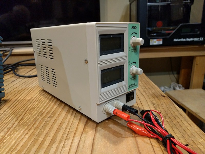
Good power source to avoid multiple causes.
if not you may encounter problem such as : too much noises, current drop if powering with USB -
Good wire
Do not trust jumper wires and bread boards.
Use experienced wire. -
Reliable measuring instruments
Clues
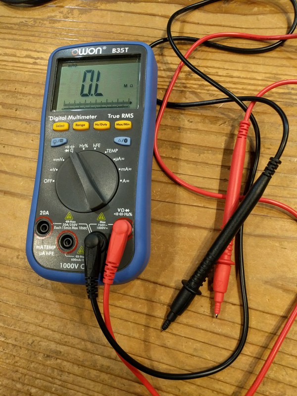
Tester
- Voltage
- Current
- Temperature
- Smell
- Sound
Oscilloscope / Logic analyzer / protocol analyzer
- Waveform
- Signal timing
Spectrum analyzer (few mega Hz accurancy)
- Signal spectrum(周波数特性)
Debugging tool in our lab
- Tester
- Stabilized power supply
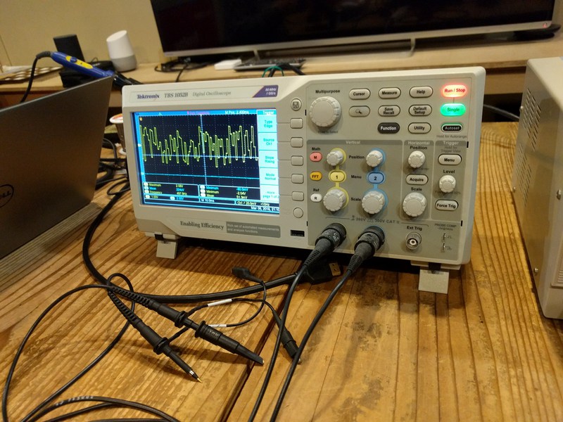
- Oscilloscope
- Tektronik
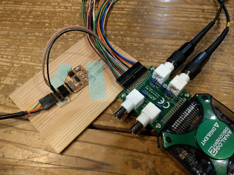
- Digilent Analog Discovery *
- Tektronik
* Digilent Analog Discovery 2
Apporx 60MHz resolution oscilloscope. Commonly used among electronics students. It has multiple functions in it:
- Scope : Check wave shapes.
- Wave generator
- Pattern generator
- Power Supplies
- Logger
- Logic analyzer
- Protocol analyzer
- Spectrum analyzer
The frequency of the ociloscope should be 3 times bigger than the signal you want to observe.
E.g.) If micro controler runs in 20M you will need 60MHz.
Setting up an oscilloscope
Wiring
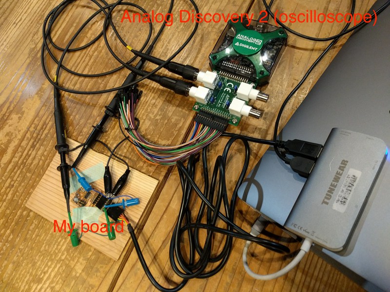
The board and oscilloscope both should be connected to PC.
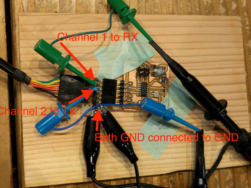
attach prove of channel 1 to RX and 2 to TX in FTDI pins. (We made an extension board in order to make it easy to connect prove to designated pins with out any unintended contact.) Both GND electrodes should be connected with GND pin in FTDI as well.
Setting on Waveforms
Download Waveforms app from here
- Probe setting
Since we are using probe that attenuate signal to 1/10
Attenuation : 10X - Triger point setting
Mode: Repeated / Nomal
Condition: rising
Channel: channel2 (set to TX)
level: 1V (adjust to logic level of micro computer) - Adjust Base and Position of the time setting
so that you can see wave pattern properly. - Offset Channel1 & 2 to observe them parallel
Oscilloscope wave pattern
Once you have done setting oscilloscope, hit “Run” button in upper left corner in the window to start observing. Then hit “Single” button right next to “Run” button to pause and capture the wave pattern.
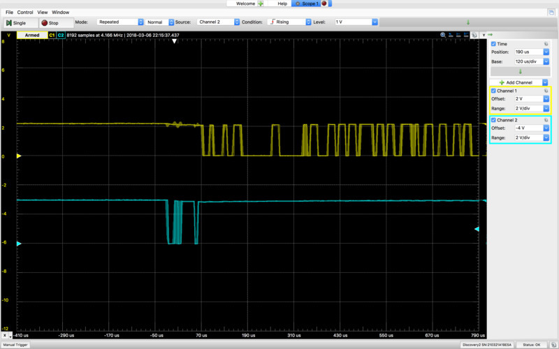
Here is what we got from our oscilloscope
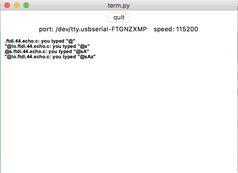
and this is the result of running program.
Try reading law wave pattern
TX
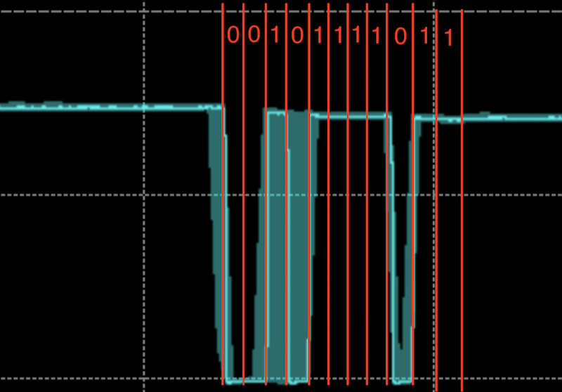
Looking at bule Channel2 wave pattern (which is monitoring TX of FTDI pin), the wave consist of two electrical state (2 different voltage) HIGH(1) and LOW(0).
If you try to read it from the very beginning to the end, its says…
00101111011
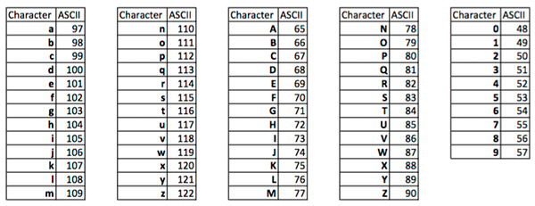
Omitting start-bit( a bit to tell the program that the data block starts here which is 0) and stop-bit( bits terminate the data block which is 11), data inside can be read as…
01011110
LSB first block of data is read form right to left, so…
01011110
Which is 7A in hexdecimal.
According to ASCII code list, 7A is encoded as “z”.
“z” is typed in the program window.
Something going wrong in RX signal
We also analyzed RX signal and wave pattern and the characters shown on the program matched.
When we look into the C file (hello.ftdi.44.echo.c), respond from the board should start with “hello.ftdi.44.echo.c:”, but it doesn’t.
put_string(&serial_port, serial_pin_out, "hello.ftdi.44.echo.c: you typed \"");
Each time we receive data, first few characters changes randomly.
As the wave pattern matches the result we get, I suspect that it is a problem of the software. However, we couldn’t dig in any further.
Protocol Analyzer / Logic Analyzer
By using protocol analyzer or logic analyzer, it is no longer necessary to stare at raw signal pattern and ASCII code list back and forward to analyze the data in the signal.
TX: D00
RX: D01
bits: 8bit
Stopbit: 2bit
Parity: none (bit for error detecting)