Week 10. molding and casting
Assignment
- group project: review the safety data sheets for each of your molding and casting materials, then make and compare test casts with each of them
- individual project: design a 3D mold around the stock and tooling that you'll be using, machine it, and use it to cast parts
group assignment
see FabLab Kamakura's group assignment page.
design a 3D mold
I made a surfboard in week 8/computer-controlled machining. This week, I decided to make surfboard fins by molding and casting. So, let's start modelling fins first.
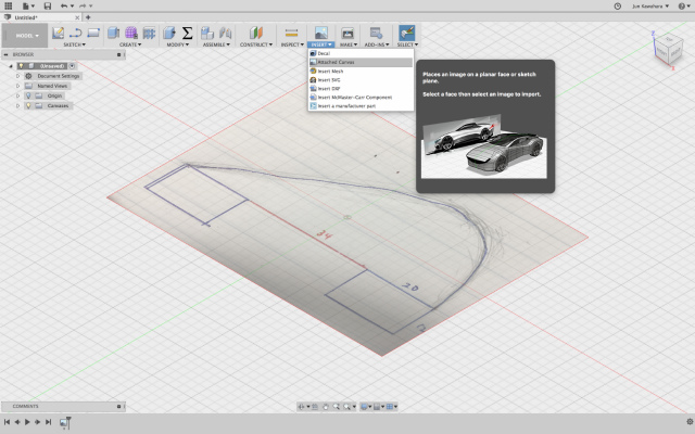
I used Fusion 360 and designed a fin in reference to this tutorial, "Sculpting Waves Creating Surfboard Fin with T-Spline Bodies."
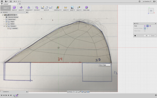
First, [Attached Canvas] and insert an image I draw.
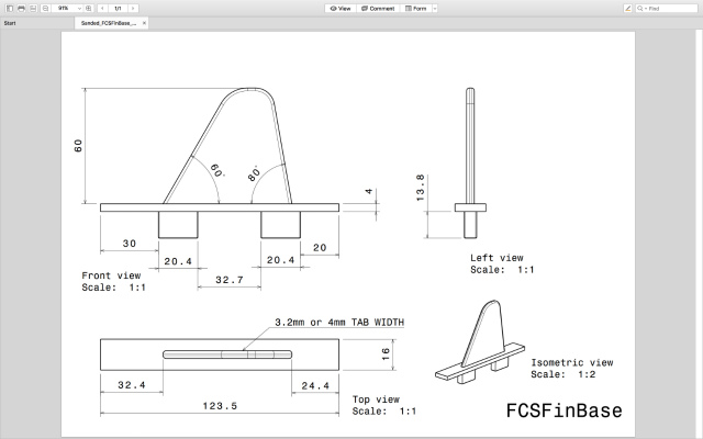
I wanted a fin to fit into FCS type finbox, so I used dimensions this schematic.
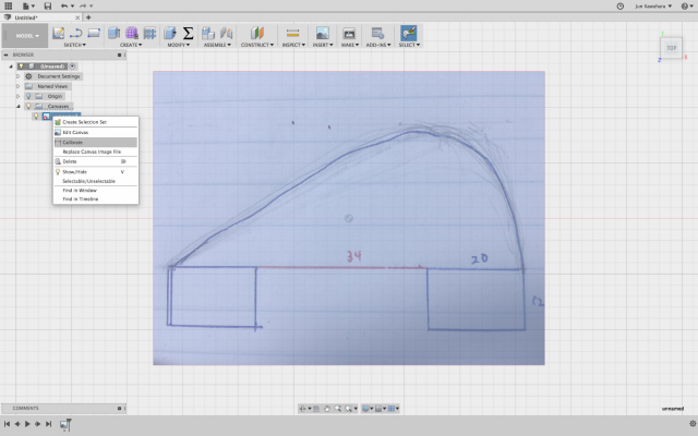
I used [Calibrate] to make an exact scale of a fin.
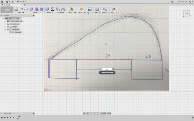
Input a base dimension.
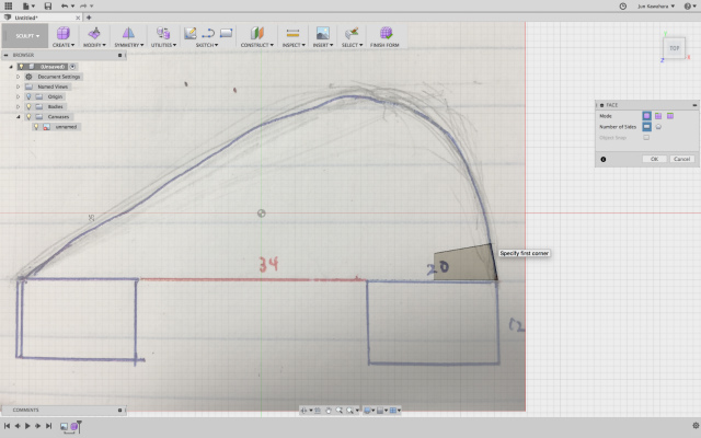
Next, [Create Form] and select [Face] feature.
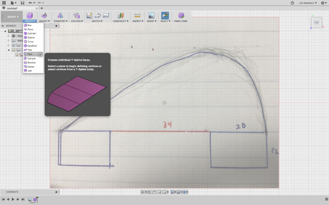
I used [Simple] mode to draw the first box.
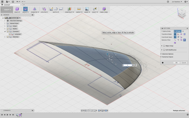
Next, I switched a mode from [Simple] to [Edge] mode to draw boxes along the perimeter.
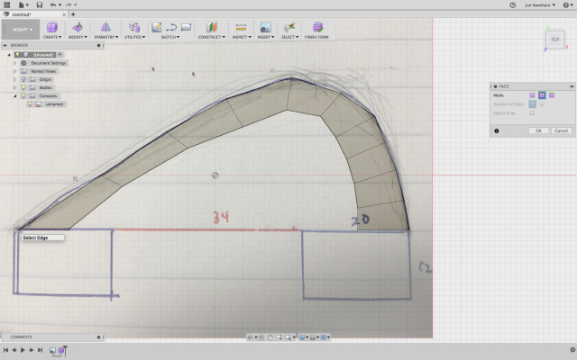
then, draw inside.
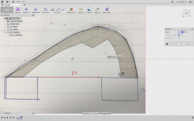
and done.
After [Edit Form] to modify the curvature of the perimeter, grab boxes and extrude a bit.
Then, [Mirror]-[Dupulicate] it to a sketch plane and [Finish Foam].
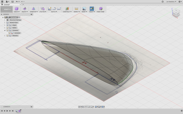
Make [Patch] the opening the bottom of the fin.
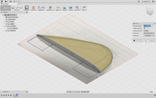
and [Stich] surface bodies to solid.
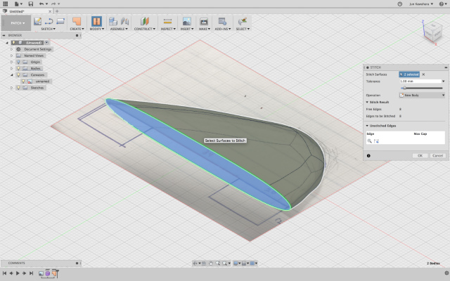
that makes them solid.
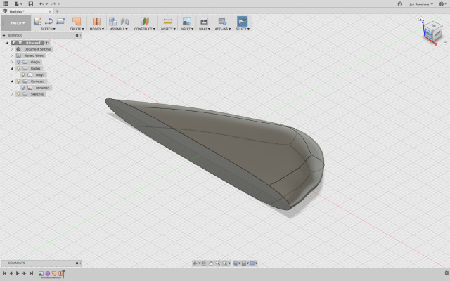
draw sketches on the surface of the fin bottom.
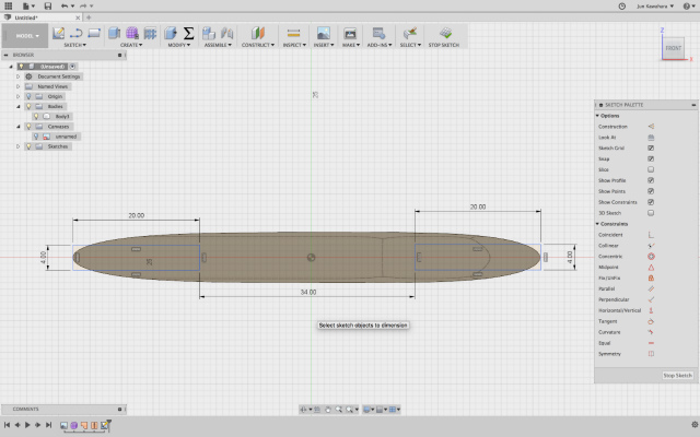
extrude the sketch surfaces based on the schematics, which made the modelling done.
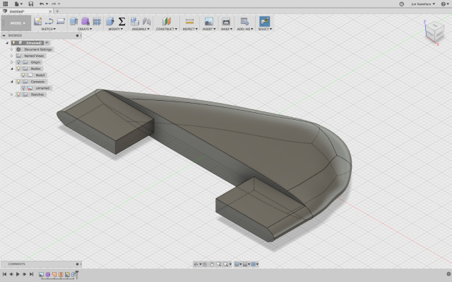
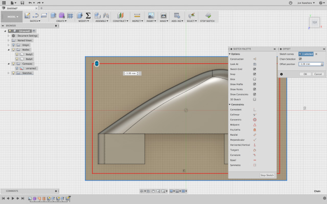
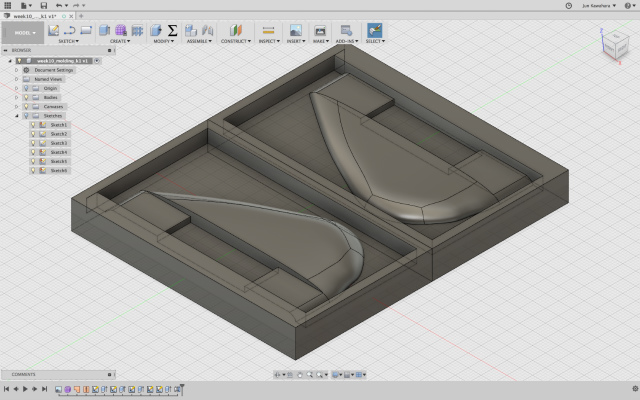
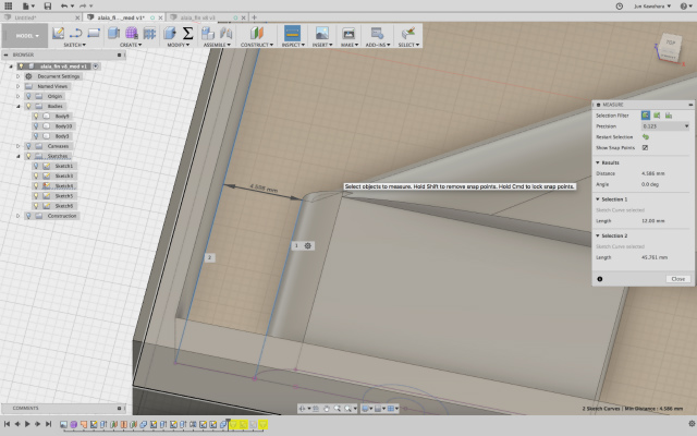
Now, making walls of the molding. draw a rectangle and offset one.
exturde a rectangle to -Z direction.
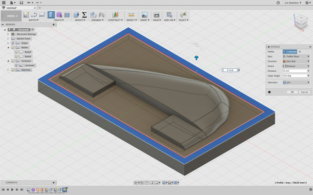
also, extrude an offset wall to the other direction.
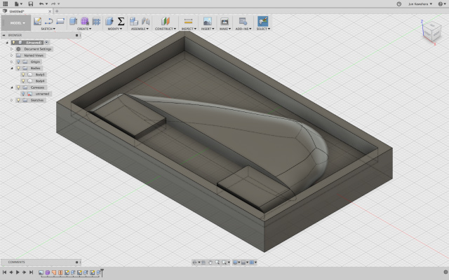
fill gaps between a wall and fin legs to use them as the opening for casting material to be poured.
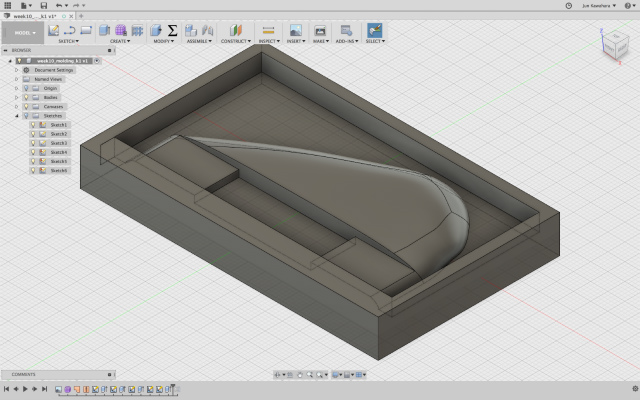
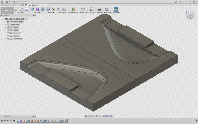
mirror the model against a surface, which makes 2-part molding.
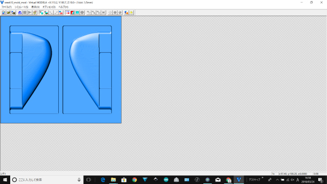
I also made a mold for 3d printing.
machine it
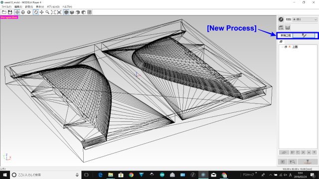
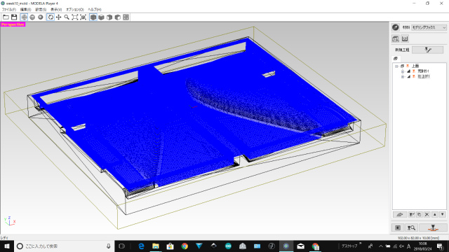
I referred to SRM-20 User's Manual.
Open a modelling file(STL file), then click [New Process]
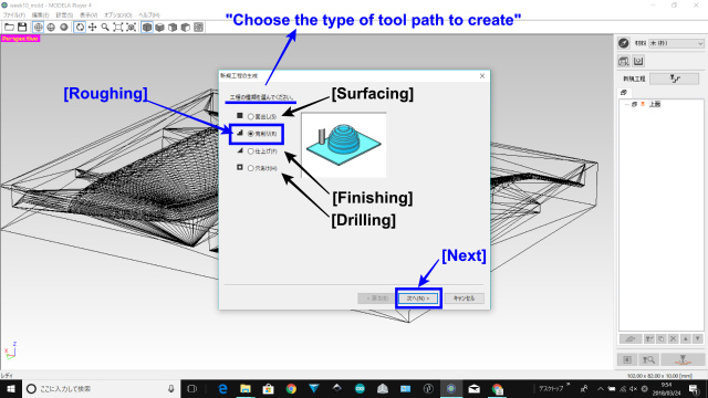
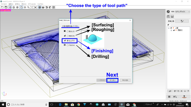
Choose the type of tool path to create. Select [Roughing], then click [Next].
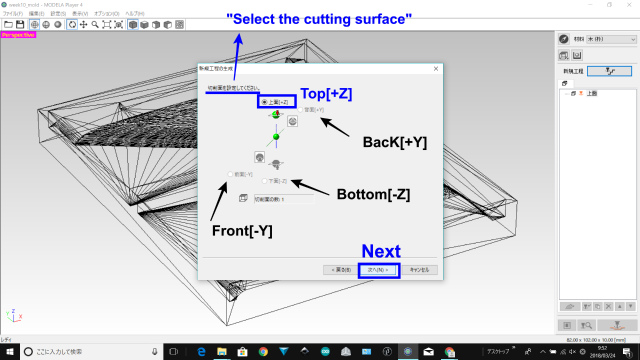
Select the cutting surface. Select the [Top[+Z]], then [Next].
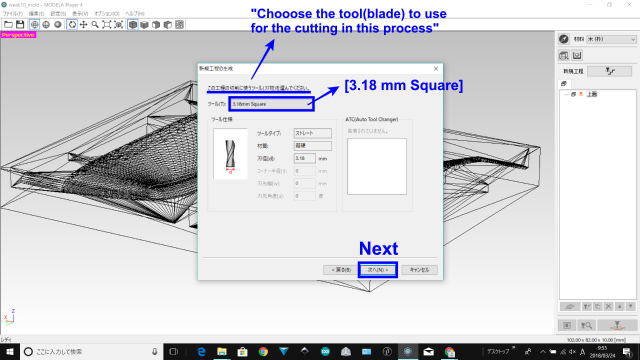
Choose the tool (blade) to use for the cutting in this process. Select [3.18 mm Square] and click [Next].
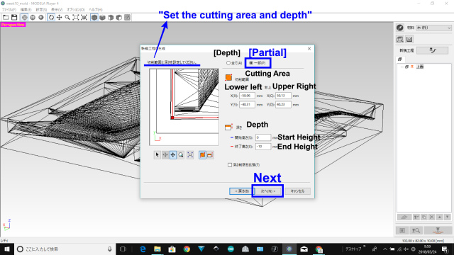
Set the cutting are and depth. Select the cutting area /[Partial] and [End Height] / [-10 mm].
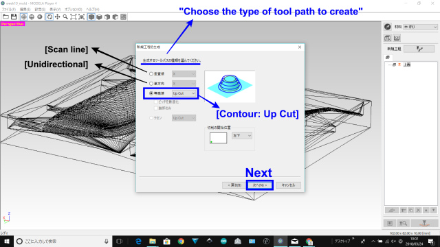
Choose the type of tool path to create / [Contour][Up Cut] and click [Next]
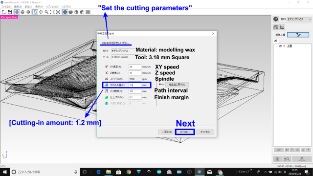
Set the cutting parameters. [Cutting-in Amount] / 1.2 mm. Other parameters were default values.
Enter a name for this process and create the tool path : [Right Now] and [Finish]
Click [New Process], then select [Finishing]
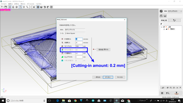
select the same parameters as the previous process except setting the cutting parameters. [Cutting-in Amount]: 0.2 mm.
Enter a name for this process and create the tool path : [Right Now] and [Finish]
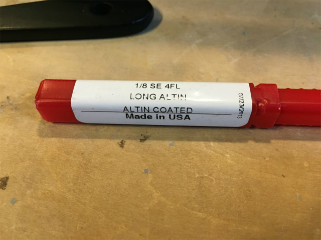
I used 1/8 inch (3.18 mm) long AlTiN drill bit.
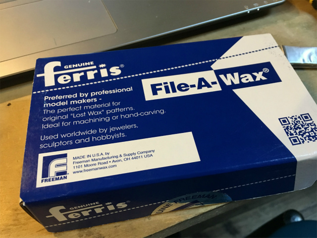
modelling wax was Ferris® File-A-Wax® and its SDS(blue).
let's get started
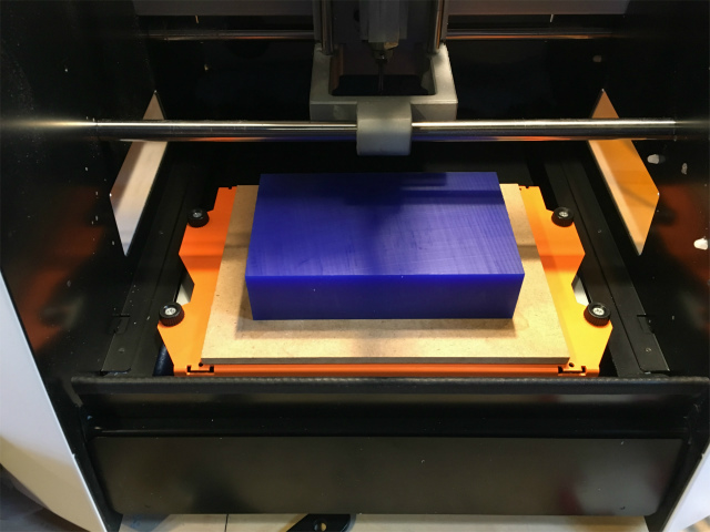
milling in progress!!
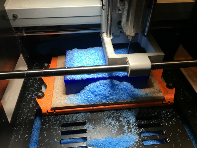
milling done successfully...I believed at this moment.
casting parts with subtractively manufactured mold
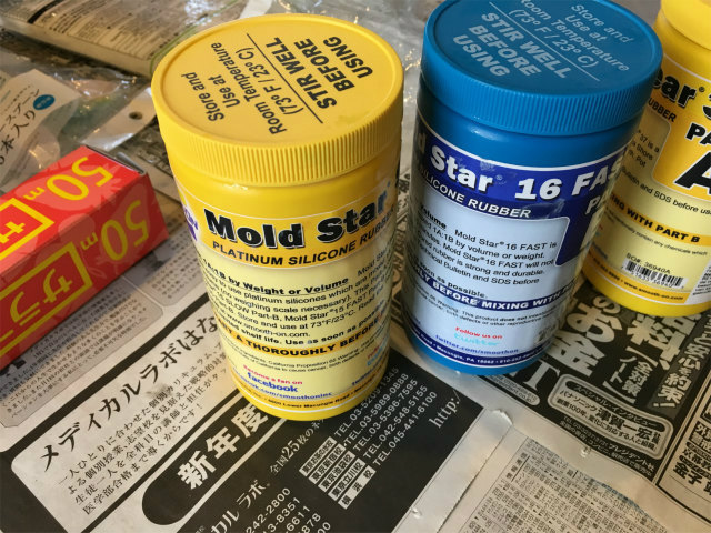
I used MOLD STAR 16 FAST as a molding material
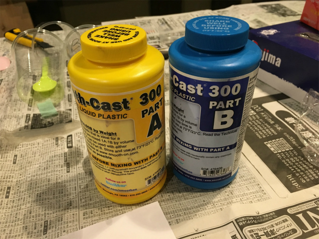
and SMOOTH-CAST 300 as a casting material.
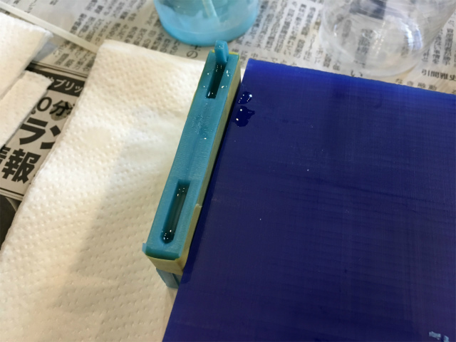
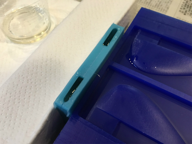
I mixed molding materials (A/B = 10/9 by weight) and poured it into a mold.
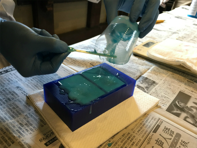
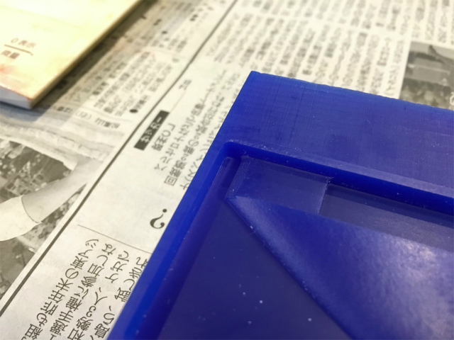
Something was wrong. There was no wall which was supposed to exist!
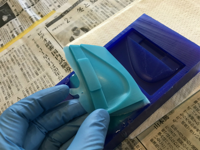
The mold was not appropriately milled.
The reason was that a gap between the wall and a fin was so small that a drill bit couldn't go into the gap. The drill diameter was 1/8 inche(3.18 mm) but, the gap was smaller, 1.75 mm.
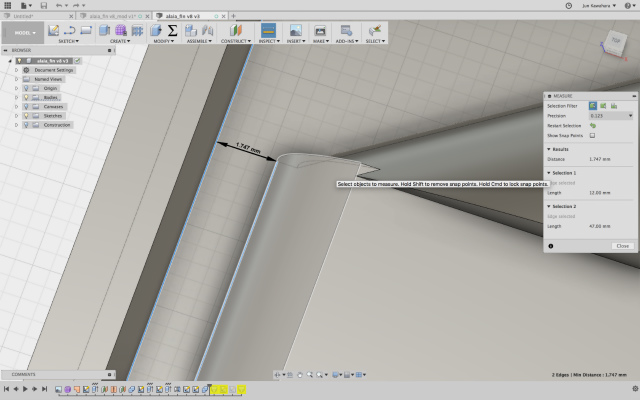
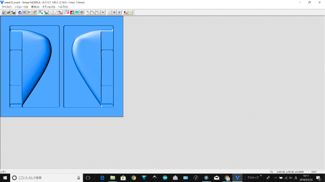
It was apparent that a drill didn't mill from the preview which I didn't look carefully...
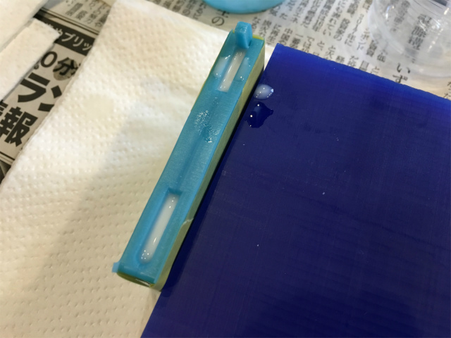
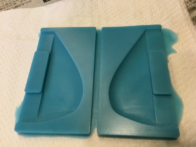
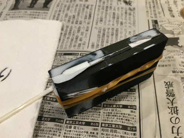
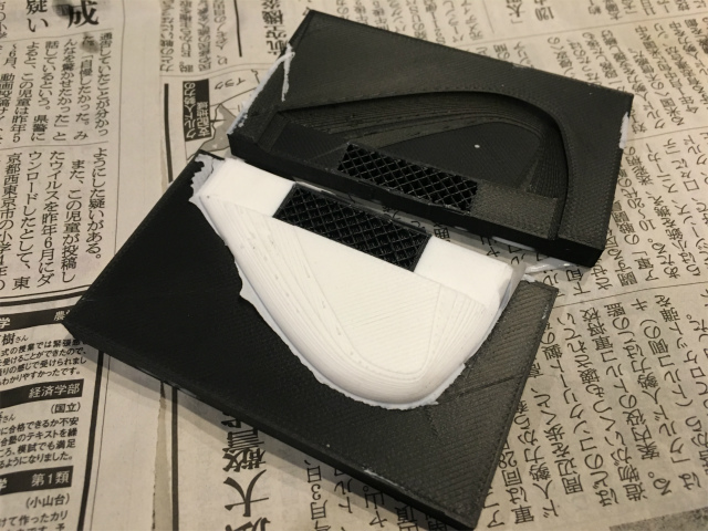
I will modify a design later, but I put a fragment as an improvised wall and poured casting material into it. There was a leakage from the wall-less part.
The casting material was transparent right after mixing.
(note: I also forgot to make an alignment part, so I carefully aligned the molding.)
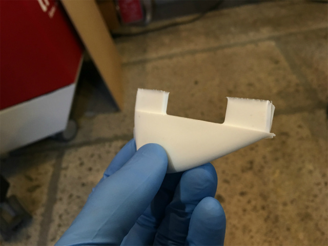
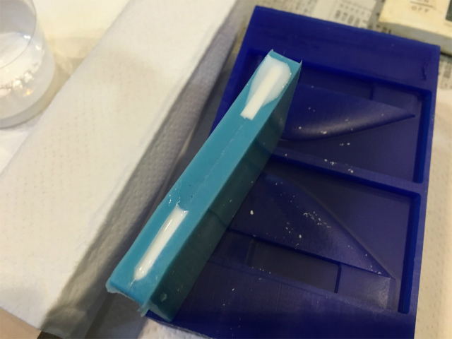
It gradually became white and hard.
It looked pretty nice, but I was not completely satisfied because of the fake wall.
redesign
I went back to Fusion 360 and widened the gap.
I checked milling preview, and the result would be good.
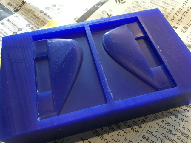
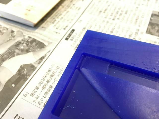
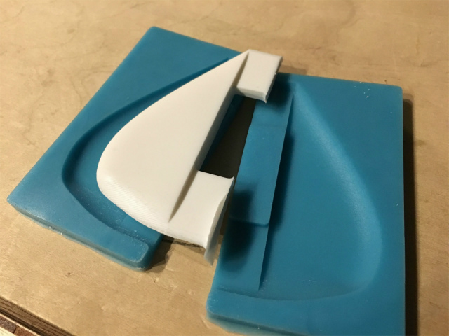
I milled a wax again and got what I wanted.
This time, the molding had a wall!
There was no leakage in this trial.
After about 10 minutes, it turned white...
and I was happy with the result!!!
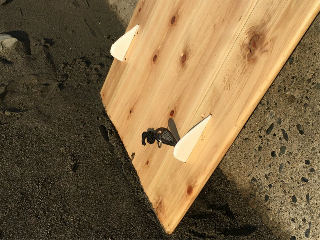
Next day, I went surf trip with these brand new fins!!
casting parts with additively manufactured mold
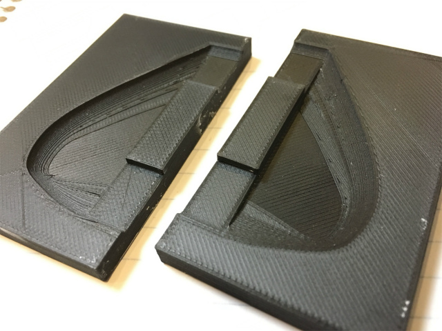
3d-printed molding was a little warped, so I pressed moldings with rubber bands.
The reproducibility of casting was pretty amazing! Layer lines were perfectly reproduced. It was a casted fin but looked like 3d-printed.
files
molding and casting
fin molding for milling: fusion 360 format (.f3d)
fin molding for milling: STL format (.stl)
toolpaths for Modela Player: Modela Player project files (.mpj)
fin molding for 3d printing: fusion 360 format (.f3d)
fin molding for printing: STL format (zipped) (.zip)