Week8 : Computer-controlled Machining
Modular Kumiki Shelf
Check our group page for the parameter setting of CNC
Download data
Design
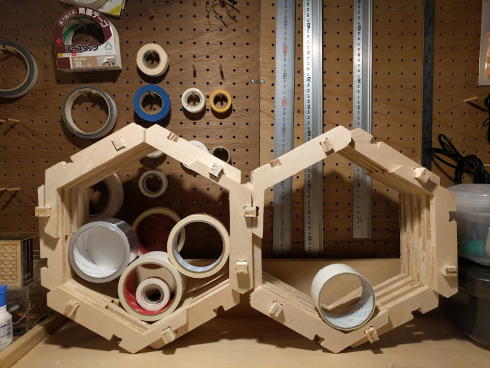
I recently assigned to make a shelf to store overflowing amount of electric parts in the lab. The requirements was quite simple: that can store the box in designated size, and can be easily extended or reduced to suit the space and the amount of the contents.
First design looked like this.
I thought it is like to bring shotgun to kill a mouse, using CNC shopbot to produce something like this. This could easily made by hand, and overall, it looked boring.
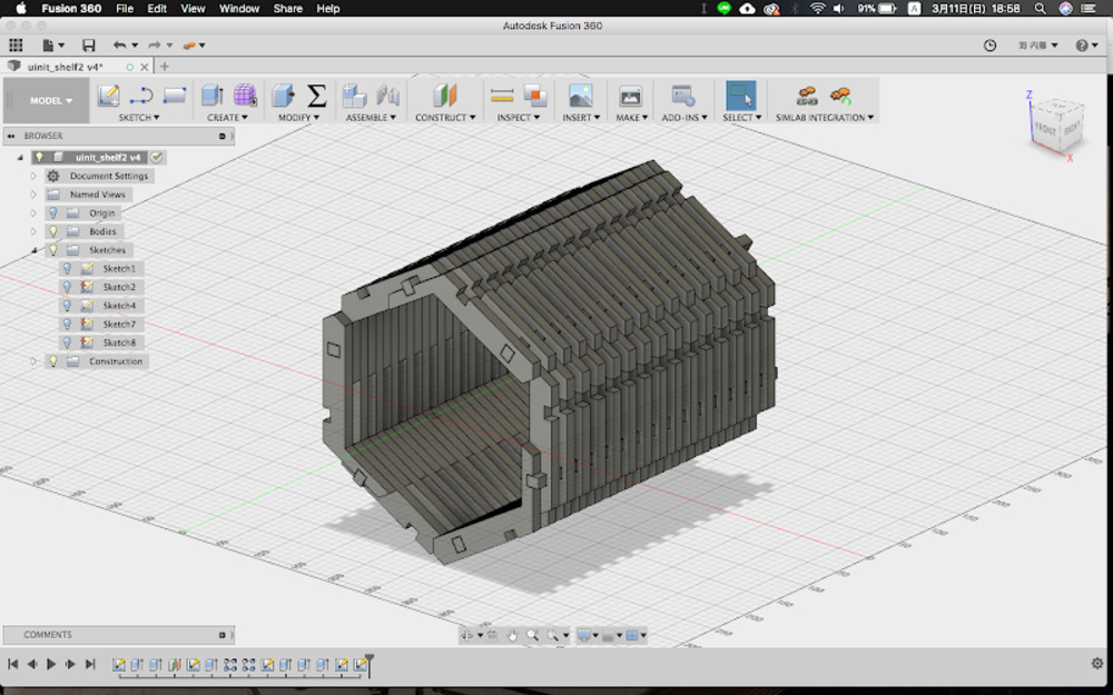
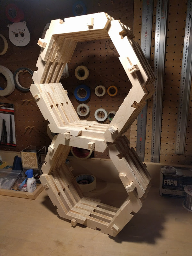
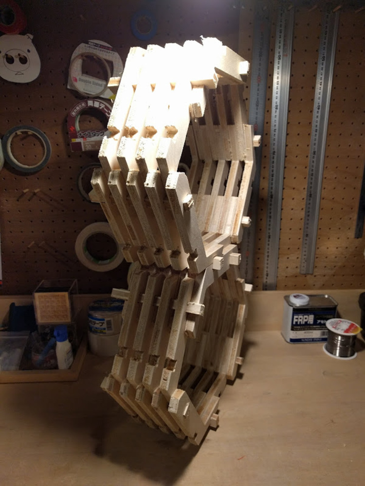
I tried out with hexagonal shape and it worked well.
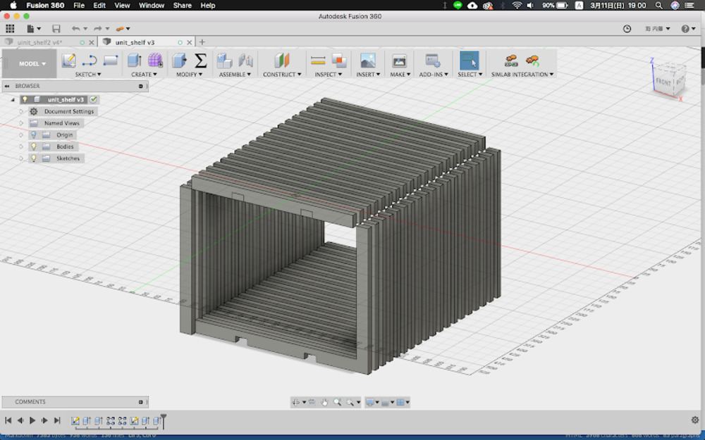
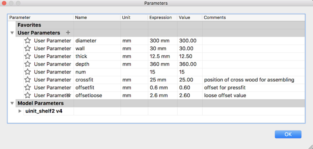
The model could be parametrically modified, such as the number of iteration along Y direction, diameter of hexagon or thickness of wall are changeable.
Design points
- Could be combined each other from any direction.
- Adopting combined wood and lattice structure which could be seen in many traditional buildings in Japan.
- Scalability (parametric) : can fit any kind of space or the amount of content to store.
Milling (Shopbot)
Date : 10th march 2018
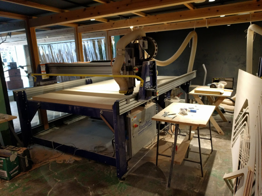
CNC machine : Shopbot
Location : Vuild inc. (Kawasaki office)
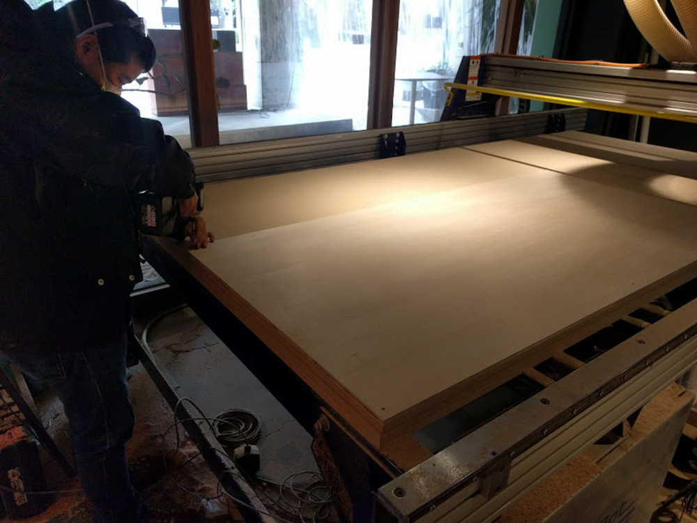
Fixation
First of all, we used screws and driver to directly fix a plywood board to the sacrifice wood on the Shopbot.
*Since the plywood board could be distorted, it is better to screw in the middle as well, not only corners. (We did not though…)
In order to avoid milling over the screws, first plot the position of the screw on the board.
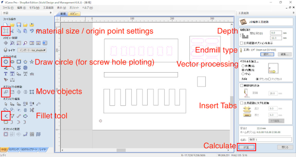
To do that, make circle and place in proper positions on CAM (VCarve).
Start CAM
- Open VCarve
- Selecting “New file” from the menu will launch job setup section
- Input the size of the plywood board (in my case it was 1980 x 910 x 12.5mm) in Job setup section.
- Set Z zero to bottom surface of the plywood
Import data
File > Import > Import Vectors
Import data you made. It could be in ai or other data format (dxf, etc.)
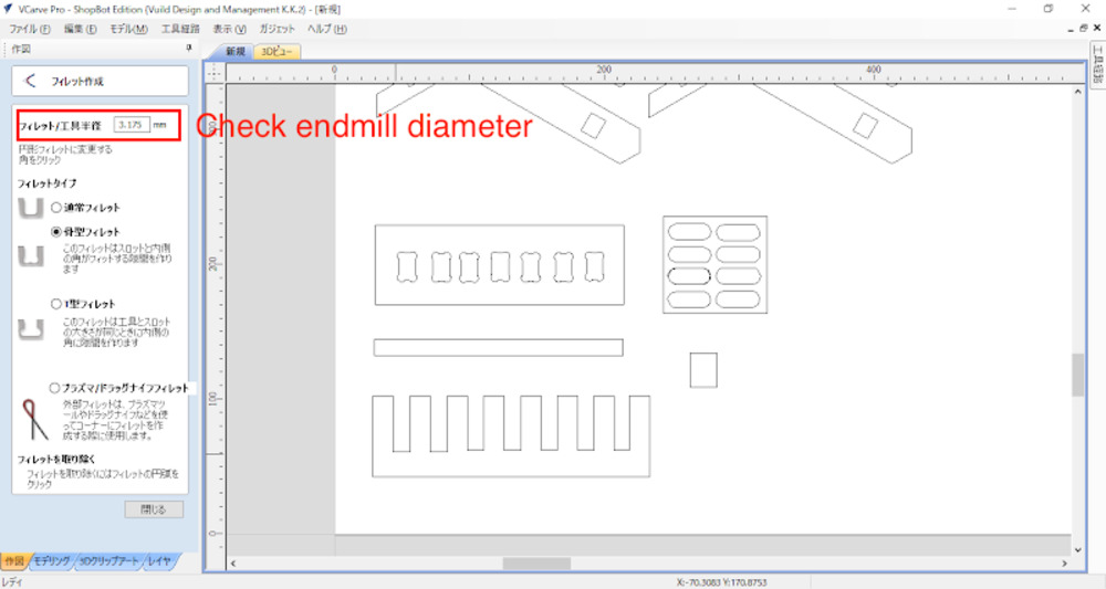
Put fillet
Insert fillet in the corner of the paths. You will need it to get designed dimensions for holes, pits, etc.
Make endmill path for screwing holes
- Place simple circle with endmill diameter to the point you will screw.
- Select “screwing holes”(穴あけ加工)
- Go to Endmill path (工具経路) > Drilling(穴空け加工)
- Milling Depth
Set depth as board thickness + 0.2~0.3mm to make sure completely cut. (in my case 12.8mm) - Check Endmill type (in my case it was 1/4" Downcut 57-910)
- Hit "calculate"
New endmill path will be added in the path list.
Make endmill path for cut line
- Select “2D silhouette endmill path”(2D輪郭工具経路)
- Milling depth
board thickness + 0.2~0.3mm - Vector Processing
Inside / Left. Direction : Downcut - Insert tab
for 12mm plywood Length :
Length : 8mm / thickness : 6mm (Shopbot owner recommendation)
However, it depends on material type, thickness, machine spec etc. - Hit “calculate”
- Save path
Check “post processor” Mine was "Shopbot TC (MM)(*.sbp)"
You may divide whole milling process into some steps, and put them in any order you want.
I had to fix my plywood board with screw before start milling, so I saved paths for screw holes and cut paths separately.
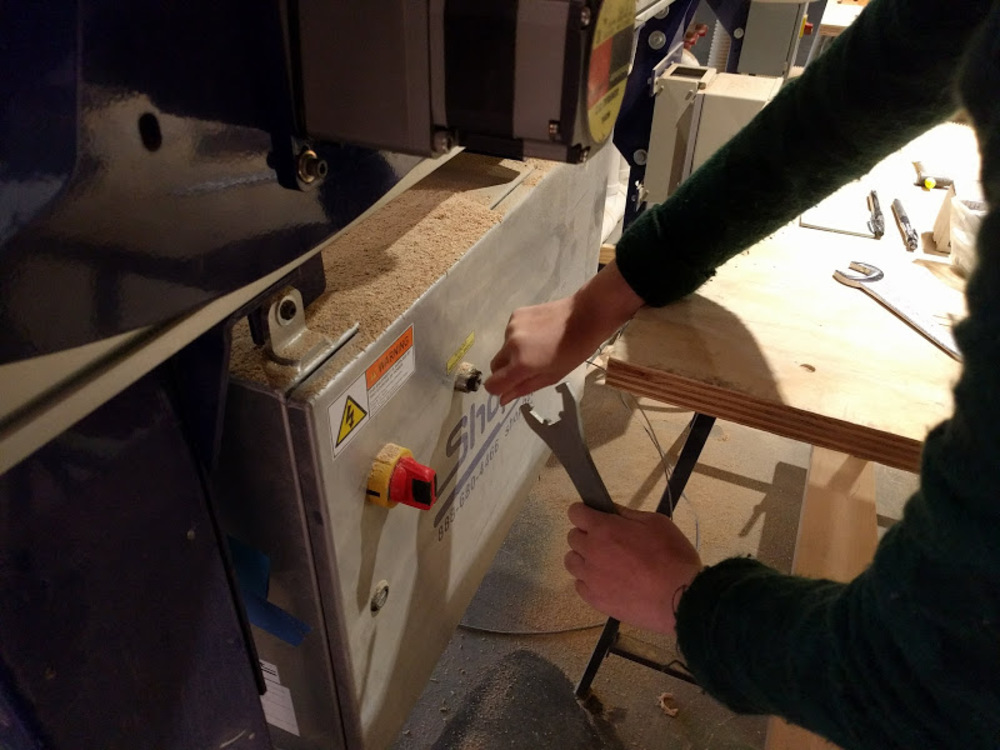
Change endmill
Use two wrenches to loosen the collet.
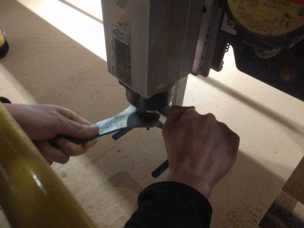
Endmill, collet and scover nut have detached.
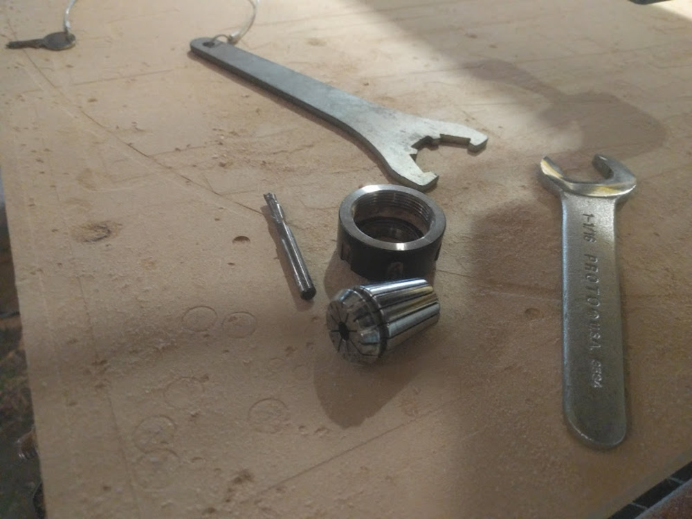
Do the opposite process, to attach the designated endmill to the collet and put them back.
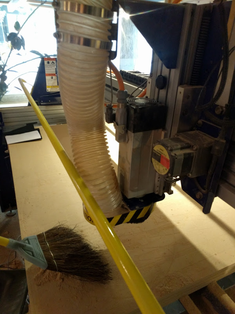
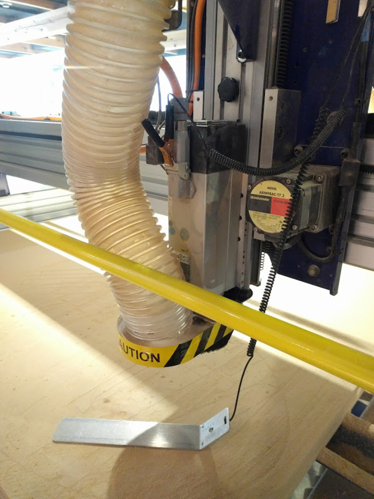
Then attach vacuum head.
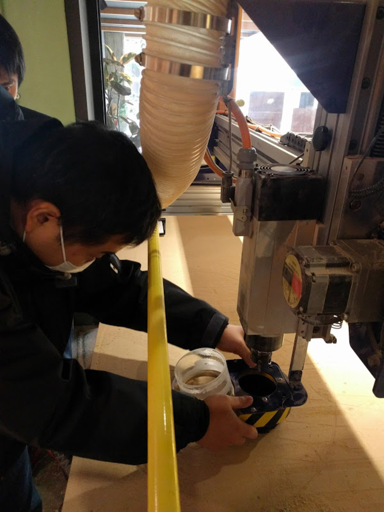
Adjust height with screw right above the moter.
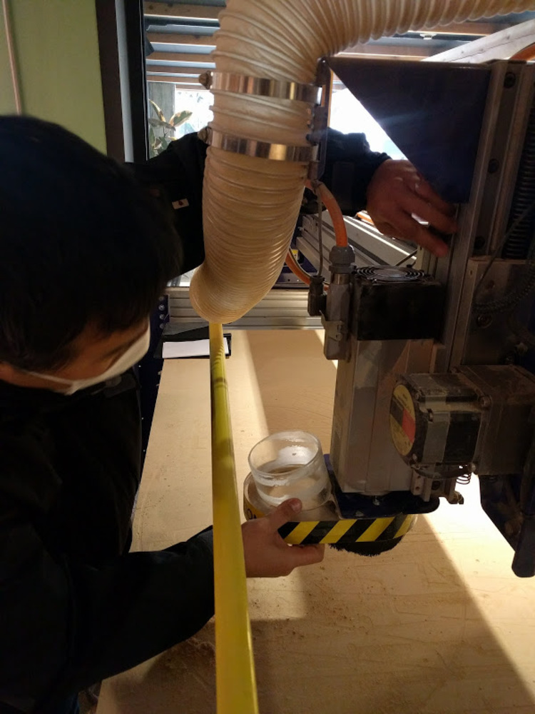
Connect vacuum pipe.
Now trun on the Shopbot!
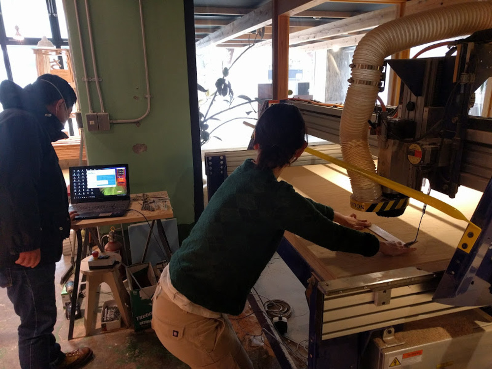
Set Z zero
Shopbots use electrode and metal plate to find Z zero point.
- Launch Shopbot software
- Set mode to Make / Move
- Clip electrode to Shopbot body, and place metal plate right beneath the endmill.
- Check the conductivity (See if the indicator on Shopbot software blinks when the metal board touches the endmill)
- Push “Adjust Z zero” button in Make / Move mode. The endmill slowly comes down until the endmill hits the metal plate (this repeats two times).
*Do this with more than 2 people (one should be holding the metal plate while the other operating the driver).
Set XY zero
In Move / Cut mode, open keypad to move the endmill position to the designated origin point (which is bottom left corner of the plywood in my case) and push “zero axes button” to set the position to XY zero.
You may hit “machine XY zero point button” to automatically move the endmill to the origin.
Final preparation
- Unlock the spindle (the keys slot on the right side of the Shopbot machine)
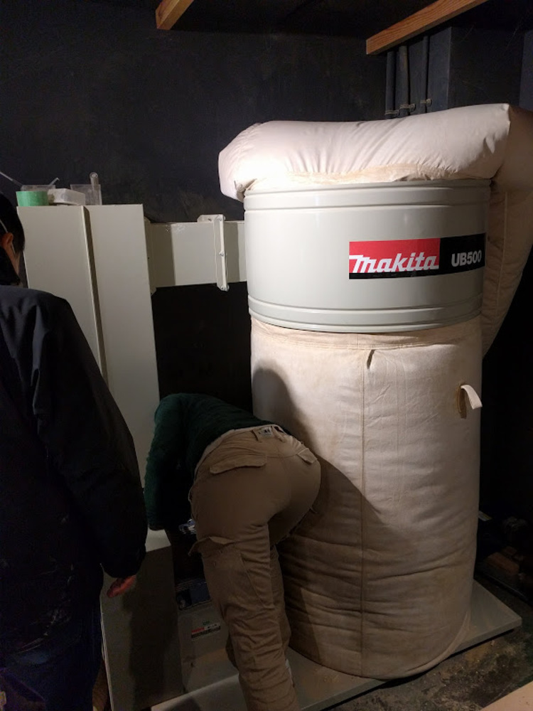
- Turn on the dust collector
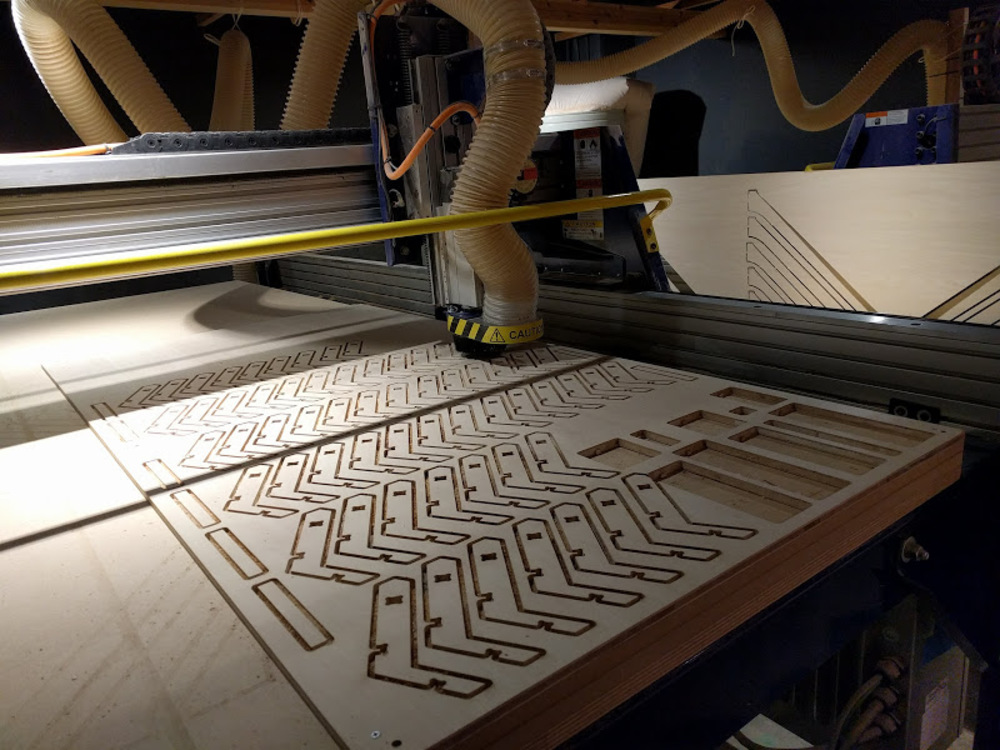
Start milling
Here is the general procedure. It is recommended to first cut the air to make sure the path is OK. To do that, first go to the machine origin and set the “offset in 2D or 3D” to “3D offset” in the Part file load dialogue which appears after you chose the file to load.
-
Hit “Cut part” button!
-
Load data
-
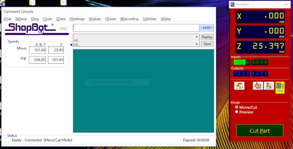
Hit “Start” button with Move / cut mode (preview screen launches if preview mode)
-
Popup message appears.
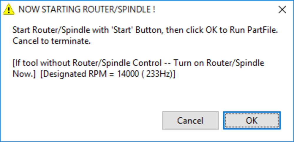
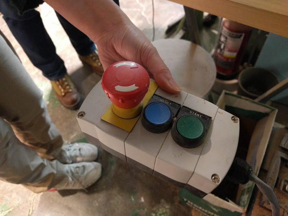
Following the instruction, push the green START button on the controller in the picture below to start spinning the endmill.
-
Press “OK” in the popup dialogue.
*DONOT push OK until endmill starts to spin. The endmill will break if milling begins when the endmill is not spinning.
First run : plot screw position
After first milling, fix the plywood with screws.
Second run : Test pattern cut
My shelf design includes two types of joints: one works just like a press-fit kit and the other one is a simple hole that another bar can go in.
I tested with both slit and hole. Upper two rows are my first test pieces that was too small. Later, I recognized that I had the thickness of the plywood board wrong. Two pieces at the bottom are my second attempt with the right thickness.

Both “slit” and “hole” worked the best with 13.0 (0.5 offset).
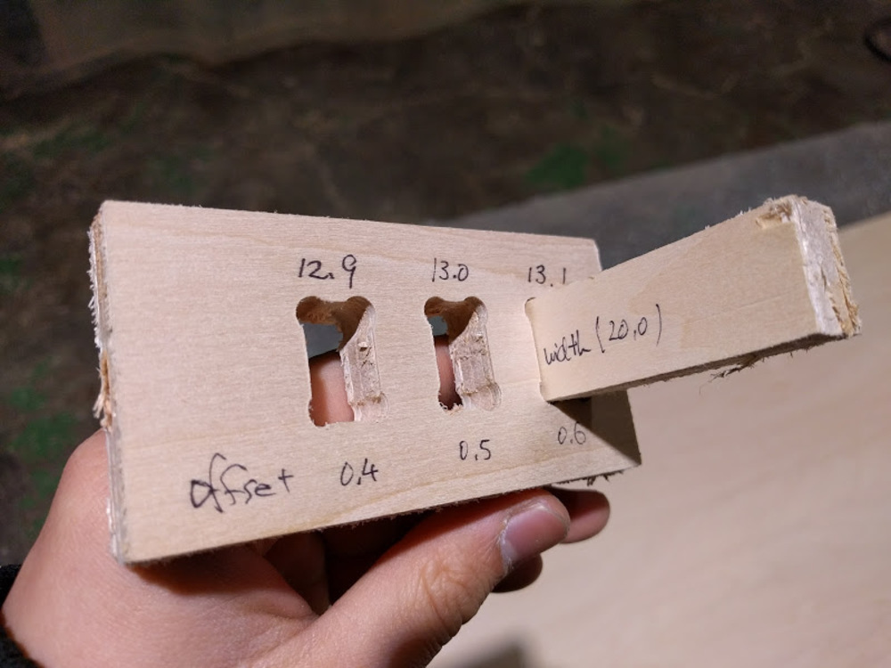
This is the last test piece with fixed width.
Decided the offset value as 0.6.
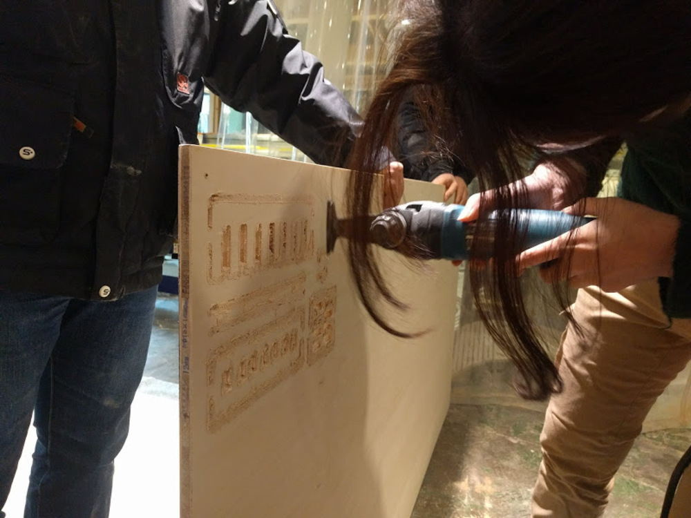
*After milling, I took the screws away and put the board off from the Shopbot to separate parts from the board.
I used small sawing machine to cut the tabs.
Third run : Real test
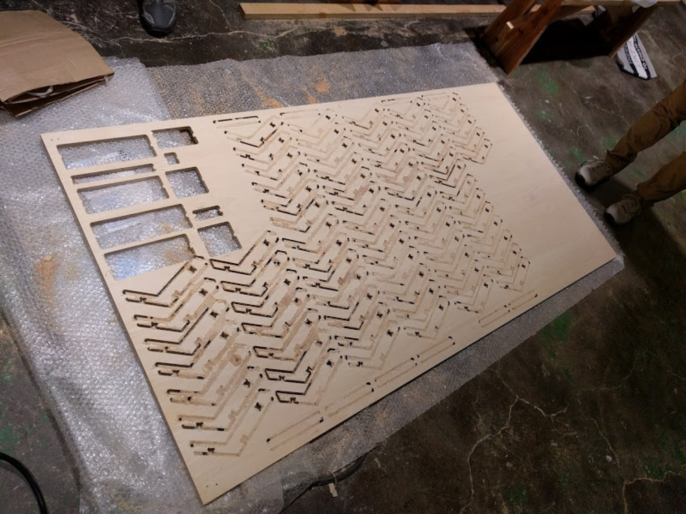
Didn’t have enough time to finish all…
Milling#2 (Originalmind : MOC)
Since I run out of time at Vuild office, I went to Fablab Hiratsuka to mill rest of the parts.
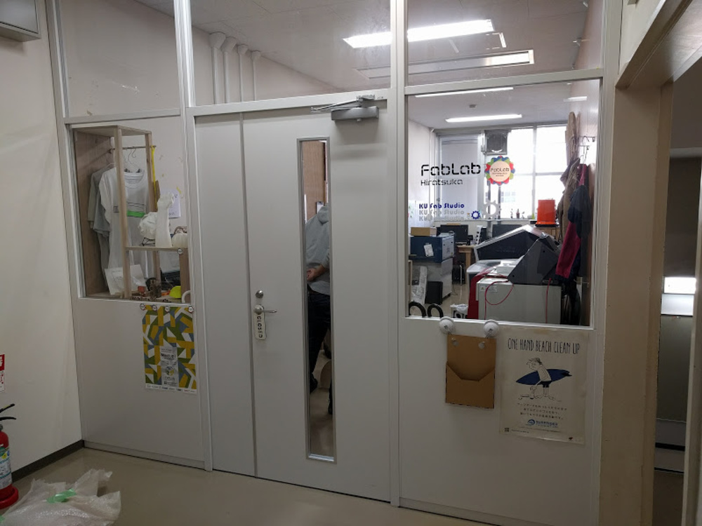
Date : 12th march 2018
CNC machine : Originalmind : MOC
Location : Fablab Hiratsuka (Kanagawa univ.)
Final result