Week9 : Embedded programing
LED blink
Check out our trial on programming other architectures:
Group page (Rasberry Pi / Microbit)
Download files
Resources
Bitwise operator in C
Fabacademy tutorial - Week8: Embedded programming
Look into Datasheet
Embedded programming week’s assignment
ATtiny24A/44A/84A datasheet
Ports as General Digital I/O
The ports are bi-directional I/O ports with optional internal pull-ups.
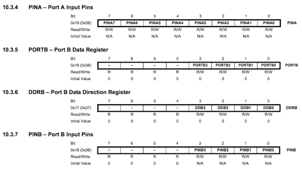
Register Description(Datasheet p.66)
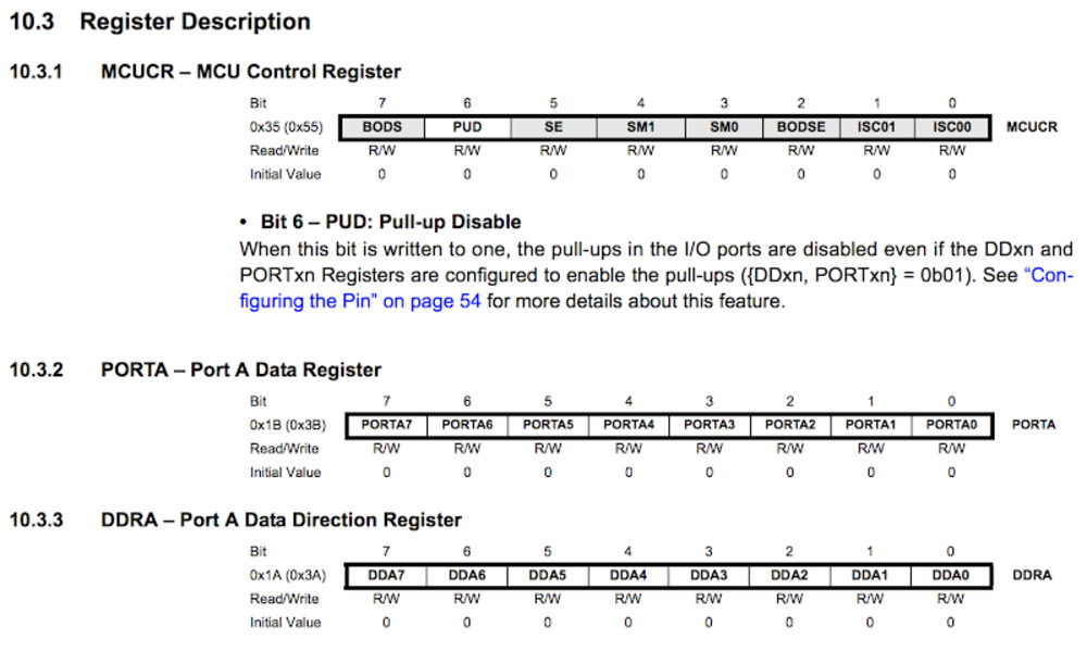
10.1.1 Configuring the Pin (datasheet p.54)
Each port pin consists of three register bits: DDxn, PORTxn, and PINxn. As shown in “Register Description” on page 66, the DDxn bits are accessed at the DDRx I/O address, the_PORTxn bits at the PORTx I/O address, and the PINxn bits at the PINx I/O address.
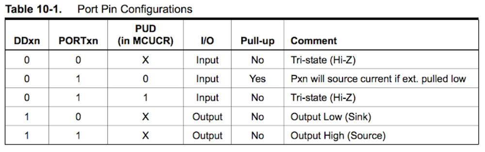
The DDxn bit in the DDRx Register selects the direction of this pin. If DDxn is written logic one, Pxn is configured as an output pin. If DDxn is written logic zero, Pxn is configured as an input pin. If PORTxn is written logic one when the pin is configured as an input pin, the pull-up resistor is activated. To switch the pull-up resistor off, PORTxn has to be written logic zero or the pin has to be configured as an output pin.
The port pins are tri-stated when reset condition becomes active, even if no clocks are running. If PORTxn is written logic one when the pin is configured as an output pin, the port pin is driven high (one). If PORTxn is written logic zero when the pin is configured as an output pin, the port pin is driven low (zero).
10.1.2 Toggling the Pin (datasheet p.55)
Writing a logic one to PINxn toggles the value of PORTxn, independent on the value of DDRxn. Note that the SBI instruction can be used to toggle one single bit in a port.
Summary
CKDIV8*
refer to Tutorial - “ATtiny44 fuses”
CKDIV8 is a prescaler feature to lower the microcontroller clock.
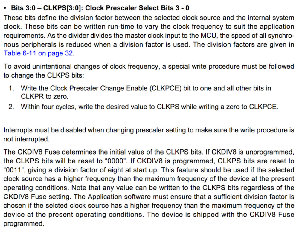
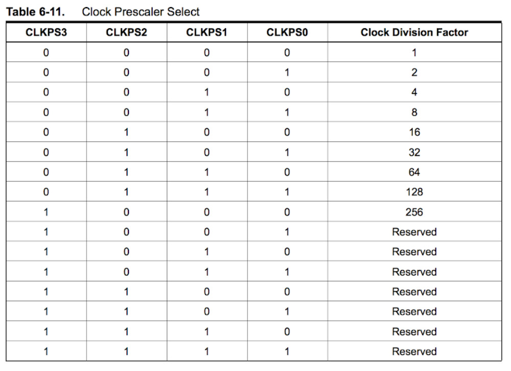
The prescaler feature can be used to change the power consumption when not high performance is required, or to ensure the performance (and programability) at any legal Vcc. This feature can be used with any clock source. The prescaler divides the clock frecuency by a defined division factor that can be configured using the CLKPS(3:0) register (Datasheet - Table 6-11), being its default value “0011” (divistion factor of 8).
When CKDIV8 is unprogrammed, CLKPS bits will be reset to “0000”. If CKDIV8 is programmed, CLKPS bits are reset to “0011”, giving a division factor of eight at start up.
The device is shipped with the CKDIV8 Fuse programmed.
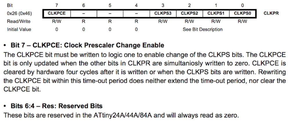
CLKPR - Clock Prescale Register (Datasheet p.31)
Programming on C
As I am not familiar with C (except for simple ArduinoIDE language), I decided to start with simple blink program.
I look for sample code on the web and found multiple ways of doing the same thing (make LED blink) on C.
Leaving note here for future reference.
Our local instructor Yuichi Tamiya’s program
He added extra code to Neil’s sample code to make LED blink.
#define led_pin (1<<PA7)
#define led_port PORTA
#define led_direction DDRA

void blink(){
	set(led_port, led_pin);
	_delay_ms(100);
	clear(led_port, led_pin);
	_delay_ms(100);
}

output(led_direction, led_pin);

blink();
Jun Kawahara made a summary on different programs that works completely the same way on his documentation page
Binary
#include <avr/io.h>
#include <util/delay.h>
#define F_CPU 2500000

int main() {
	DDRB = 0b00000100; //PB2 as output
	while(1) { 				//endless loop
		PORTB = 0b00000100; //LED ON
		_delay_ms(1000);    // wait for 1000 ms
		PORTB = 0b00000000; //LED off
		_delay_ms(1000);    //wait for 1000 ms
	}
	return 0;
}
hexadecimal
	DDRB = 0x04; //PB2 as output
	while(1) { 				//loop
		PORTB = 0x04;     //LED on
		_delay_ms(1000);    //wait for 1000 ms
		PORTB = 0x00; //LED off
		_delay_ms(1000);    //wait for 1000 ms
	}
macro
	DDRB = _BV(PB2); //PB2 as output
	while(1) { 				//loop
		PORTB  = _BV(PB2); //LED on
		_delay_ms(500);    //wait for 1000 ms
		PORTB ^= _BV(PB2); //LED off
		_delay_ms(500);    //wait for 1000 ms
	}
(1 << PB)
DDRB |= (1 << PB2); PB2 as output
while(1) { 				//loop
		PORTB  |= (1 << PB2); //LED on
		_delay_ms(2000);    //wait for 1000 ms
		PORTB &= ~(1 << PB2); //LED off
		_delay_ms(2000);    //wait for 1000 ms
	}
Use XOR operator to reduce the code lines
DDRB |= (1 << PB2); //PB2 as output
while(1) { 				//loop
		PORTB  ^= (1 << PB2); //LED on and off
		_delay_ms(1000);    //wait for 1000 ms
		}
Operators
When
unsigned int a = 60; // 60 = 0011 1100
unsigned int b = 13; // 13 = 0000 1101
| : binary or operator
a | b = 61 = 0011 1101
& : binary and operator
a & b = 12 = 0000 1100
^ : binary xor operator
a ^ b = 49 = 0011 0001
~ : binary operator that flips the bits
~a = -61 = 1100 0011
>> : binary right shift operator
a >> 2 = 15 = 0000 1111
<< : binary left shift operator
a << 2 = 240 = 1111 0000
Notation in C
a |= b equals to a = a | b.
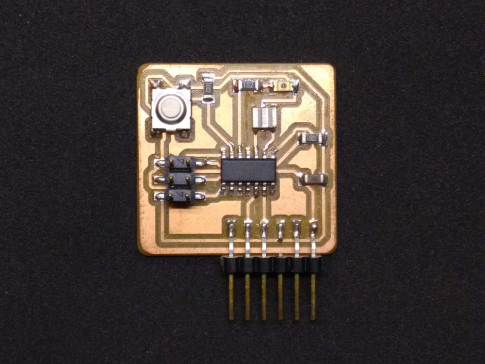
My program
I tried to write the first program on my board.
Here are the file I prepared.
blink.c
blink.c.make
- PB2 is the pin for the LED. (see Electronics production week)
0bon the head of the bits indicates that the numbers following are binary.
Makefile
Few comments on makefile. (refer to tutorial)
blink.c.make
PROJECT=blink
SOURCES=$(PROJECT).c
MMCU=attiny44
F_CPU = 2500000

CFLAGS=-mmcu=$(MMCU) -Wall -Os -DF_CPU=$(F_CPU)

$(PROJECT).hex: $(PROJECT).out
	avr-objcopy -O ihex $(PROJECT).out $(PROJECT).c.hex;\
	avr-size --mcu=$(MMCU) --format=avr $(PROJECT).out

$(PROJECT).out: $(SOURCES)
	avr-gcc $(CFLAGS) -I./ -o $(PROJECT).out $(SOURCES)

program-bsd: $(PROJECT).hex
	avrdude -p t44 -c bsd -U flash:w:$(PROJECT).c.hex

program-dasa: $(PROJECT).hex
	avrdude -p t44 -P /dev/ttyUSB0 -c dasa -U flash:w:$(PROJECT).c.hex

program-avrisp2: $(PROJECT).hex
	avrdude -p t44 -P usb -c avrisp2 -U flash:w:$(PROJECT).c.hex

program-avrisp2-fuses: $(PROJECT).hex
	avrdude -p t44 -P usb -c avrisp2 -U lfuse:w:0x5E:m

program-usbtiny: $(PROJECT).hex
	avrdude -p t44 -P usb -c usbtiny -U flash:w:$(PROJECT).c.hex

program-usbtiny-fuses: $(PROJECT).hex
	avrdude -p t44 -P usb -c usbtiny -U lfuse:w:0x5E:m

program-dragon: $(PROJECT).hex
	avrdude -p t44 -P usb -c dragon_isp -U flash:w:$(PROJECT).c.hex

program-ice: $(PROJECT).hex
	avrdude -p t44 -P usb -c atmelice_isp -U flash:w:$(PROJECT).c.hex
First 4 lines mention
- Name of the file to compile
Be careful not to include “.c”. Pay a tension to the second line that subjects the file to compile (it has “.c” within it).
- Extension of the file to compile
- Microcontroller to program
- Frequency of the board to program
Since the clock frequency are set to 2.5MHz (system clock source is prescaled to one eighth by CKDIV8*) when shipped, the frequency in this part of the makefile and C code has to be adjusted to 2.5MHz as well in order to ensure the timer to work correctly.
Otherwise, you may modify fuse to unprogram CKDIV8 register by Atmel Studio. I documented the procedure at the bottom of this documentation page.
The other lines initialize the process and compile the C script with avr-gcc.
The other part of the file (and that won’t be executed with a simple make command) consists of different instructions, that can be specified after make:
Like...
$ make program-usbtiny
$ make program-usbtiny-fuses
To look further in to the makefile, useful resource.
Run blink
Run avr-gcc compiler, program fuses and compiled C to the board.
$ make -f blink.c
$ sudo make -f blink.c.make program-usbtiny-fuses
$ sudo make -f blink.c.make program-usbtiny
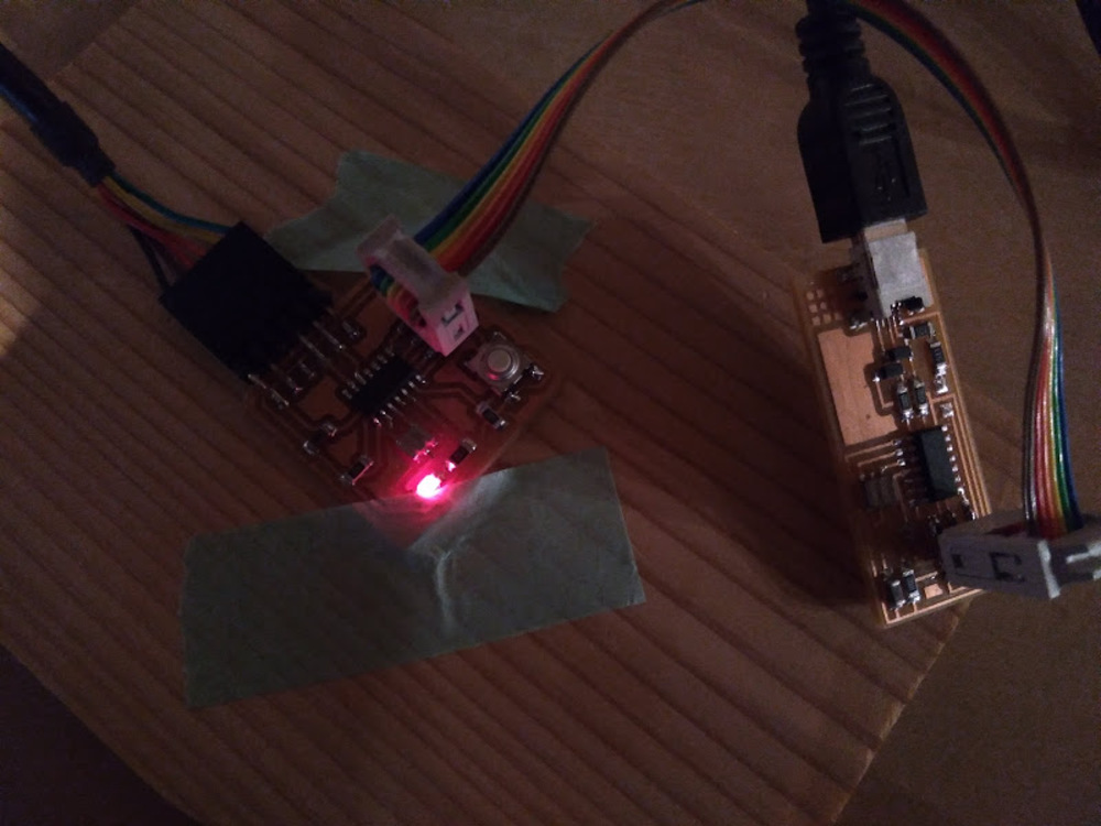
LED blink from kai naito on Vimeo.
worked!Change fuse configuration by Atmel studio
-
Download Atmel studio
-
Tool > device programming
-
Set parameters
Tool : AVRISPmarkII
Device : Attiny 44A -
Hit Apply button
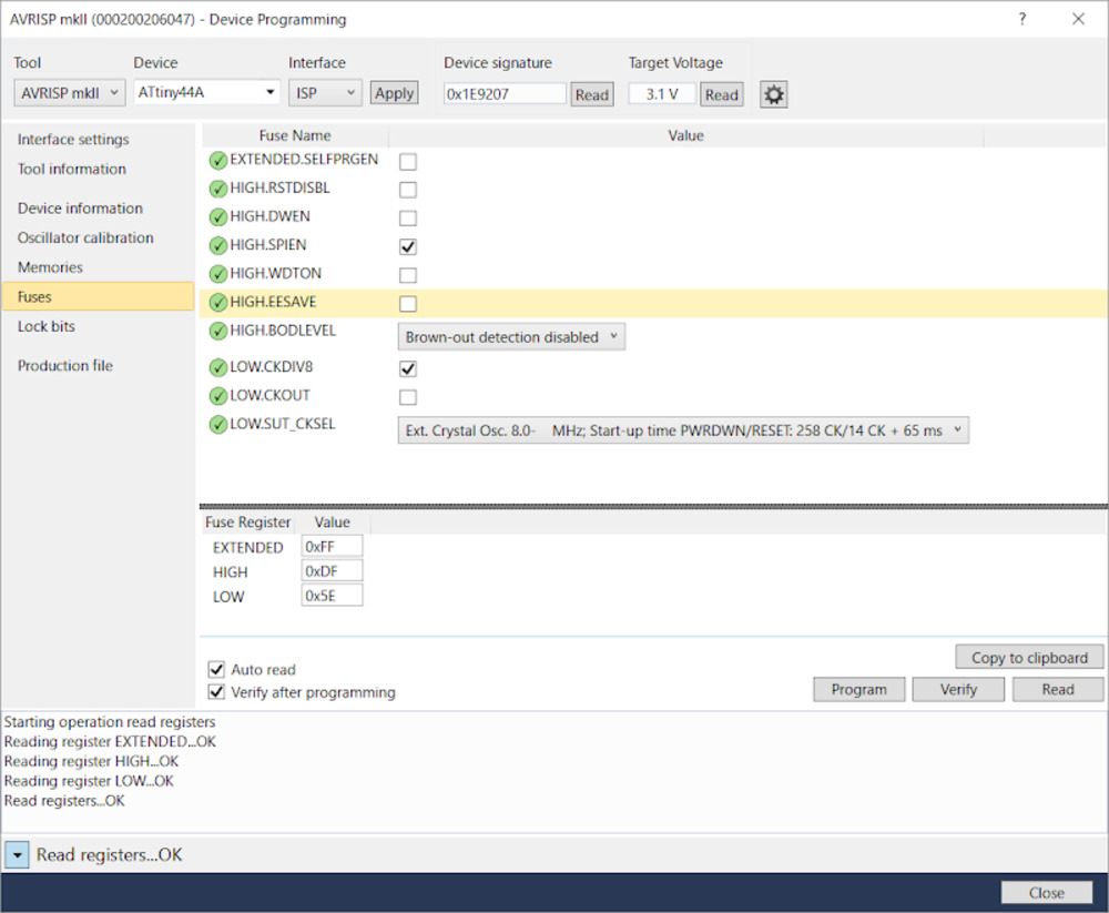
-
Change configuration
Following two register is checked in default.
HIGH:SPIEN
LOW:CKDIV8
Uncheck LOW:CKDIV8 -
Hit “Program”