Electronics Production.
Concept
For this assignment, the goal was to reproduce a
Reproducing a board involves a couple of critical steps, such as: creating a circuit layout file, milling out the board, cutout of the board as well as soldering the necessary components onto the board.
Since my experience involves creating a PCB board using the chemical-etching process, this was something new to get my mind and hands on.
Creating the Milling Files using FabModules.
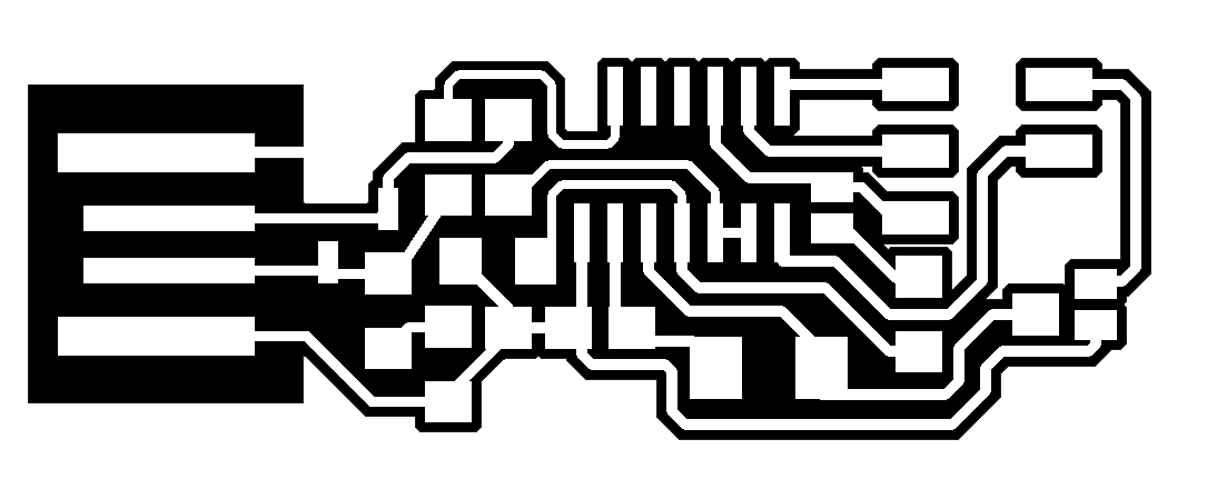
Using the Monochrome
And one for the cutout of the board.

As we navigate to the Fab Modules website, we load our PNG image. Since in our lab we benefit from having a Roland Mill MDX-40, this exact device will be chosen for the extension of the format that will be produced. Any other extension can be used accordingly. Since we are creating first the traces, the
Important settings to consider:
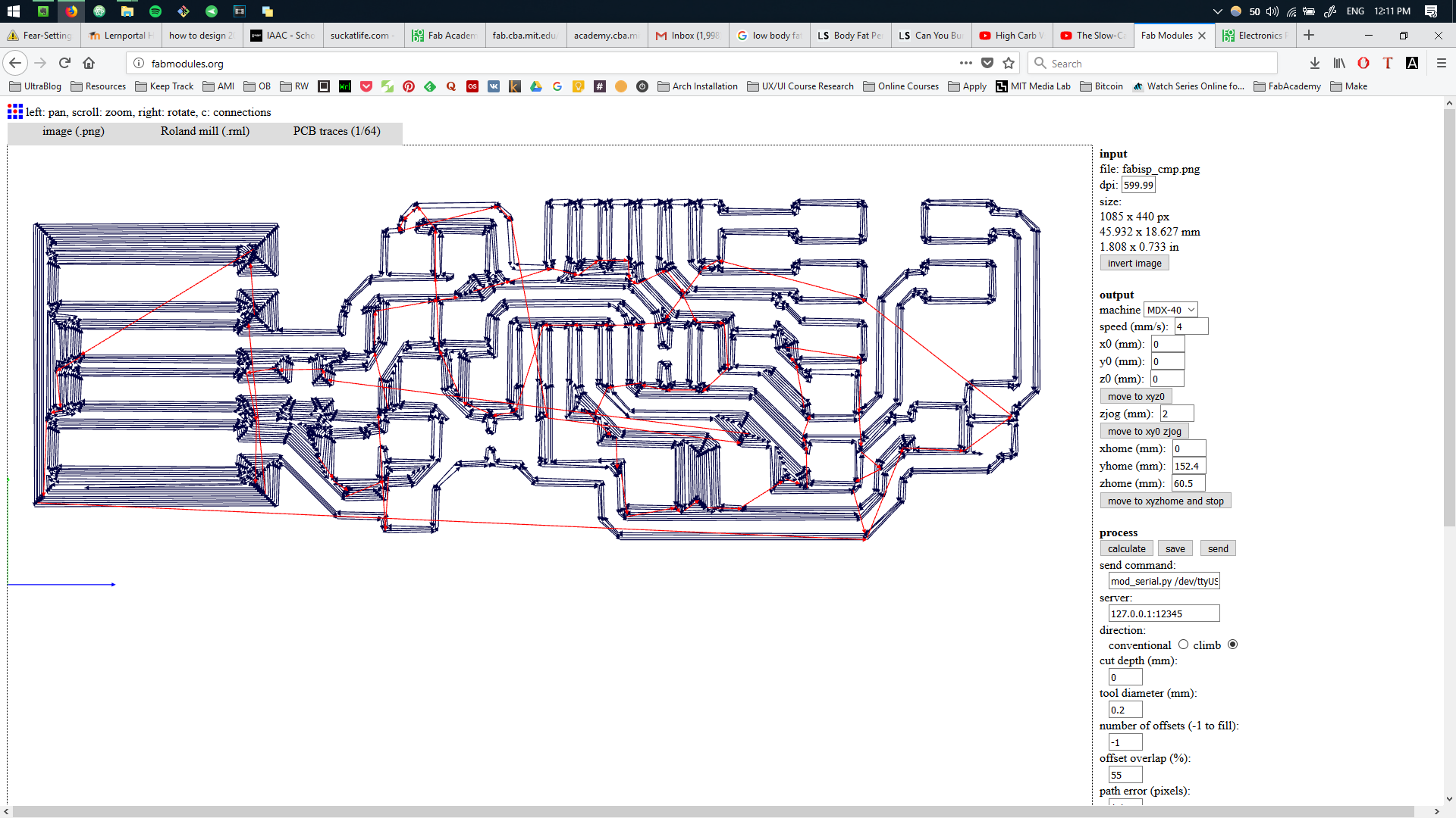
We can notice that the
We repeat the process for the outline of the board. This time the
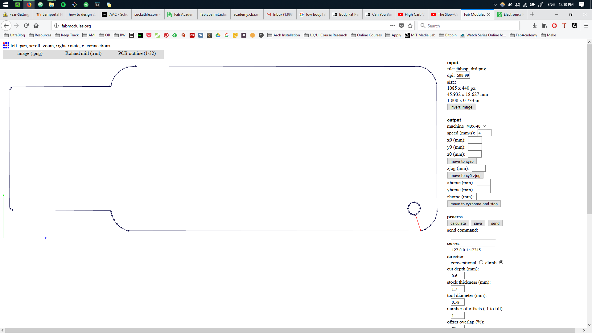
As a result we have obtained two .rml files that will be used with our CNC machine.
Roland MDX-40 Setup.
The CNC machine has an enclosure that protects the outer environment. Once the
.jpg)
For the milling job,
.jpg)
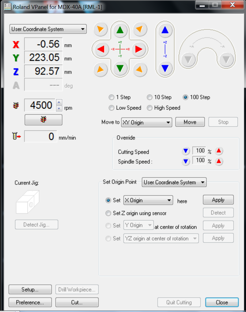
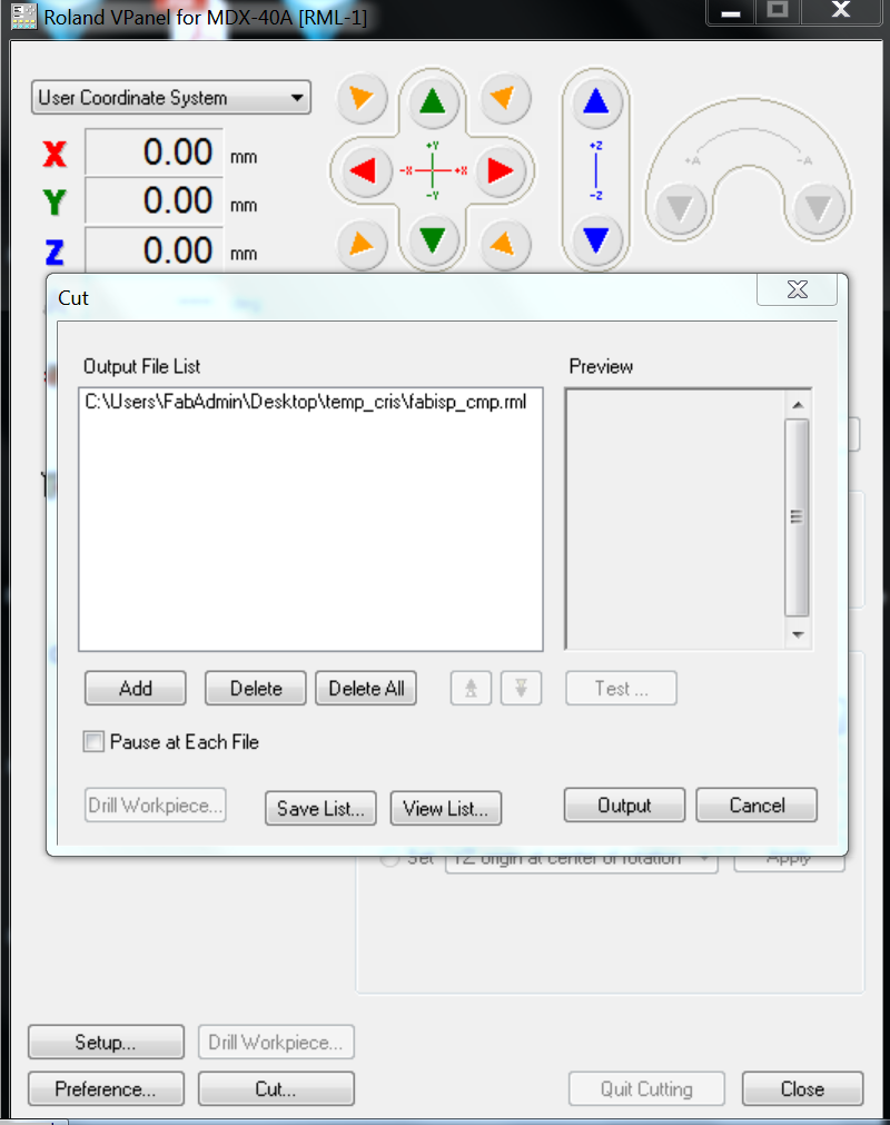
Using the software that accompanies the CNC machine, we can now specify the X,Y,Z origin points by pressing the red, green and blue arrows accordingly. The most crytical is the Z axis and needs to be done in such a way that the milling tool just
Once the origin point is set, we can load the files by pressing the
Engraving of the FABISP.
During the first attempt to mill the board, the depth was not well stated. As a result parts of the copper sheet remained unmilled. This can noticed in the next picture, where the second job was not finished.
.jpg)
Going some hundreds of milimeters deeper, or 0.003 mm fixed the job.
.jpg)
Cutout of the FABISP.
Followed the cutout process, which finalized the milling process.
.jpg)
The board is ready for soldering.
.jpg)
Soldering SMD Components.
In order to understand which components are necessary for the soldering, it is helpful to consult the schematic provided by the creator.
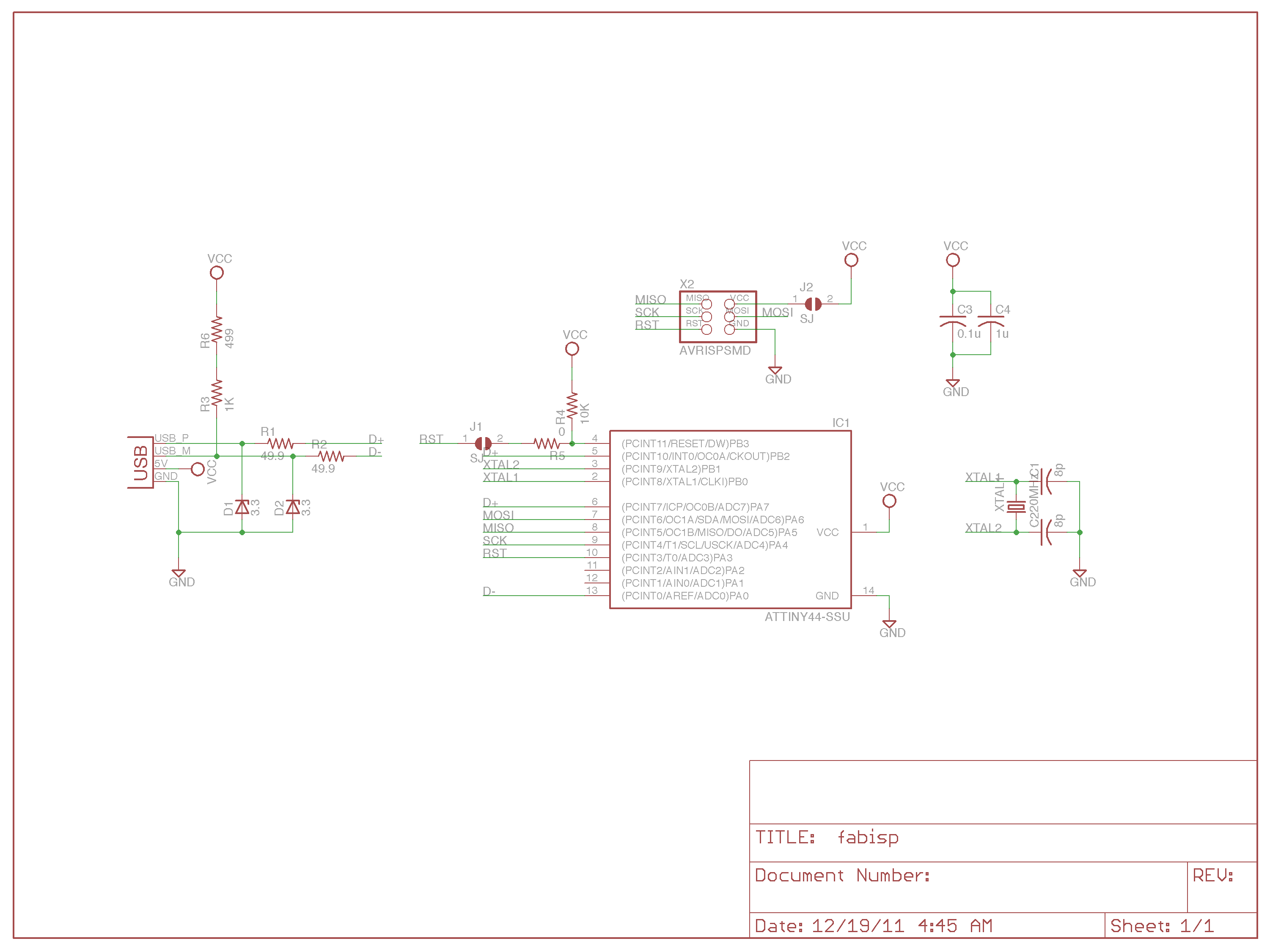
Necessary components are:
.jpg)
For the next process we will need a soldering iron, soldering material, soldering station, a multimeter and previusly mentioned SMD components.
For start we will solder our microcontroller in order to get all pins connected firmly. We start by setting our soldering tool to the necessary temperature, usually above 300 degrees to increase the efficiency and speed. We add some soldering material on one of the pad, usually the corner one.
We will go ahead and solder that pad to the designated pin of the microcontroller to enable a mechanical hold and position the processor. After which we continue by soldering each pin of the microcontroller.
*Important to notice that in this image one column of pins were skipped by accident and another board was created to accomplish the results.
.jpg)
Rest of components are soldered accordingly.
.jpg)
Now we can test using the multimeter if each of the path has electrical connection with the pin of the ATTINY44. If the value shifts from 1 in the test mode, this means the connection is established or a short exists. Otherwise the soldering was done poorly and needs to be redone or some path need to be separated.
Giving Life to FABISP.
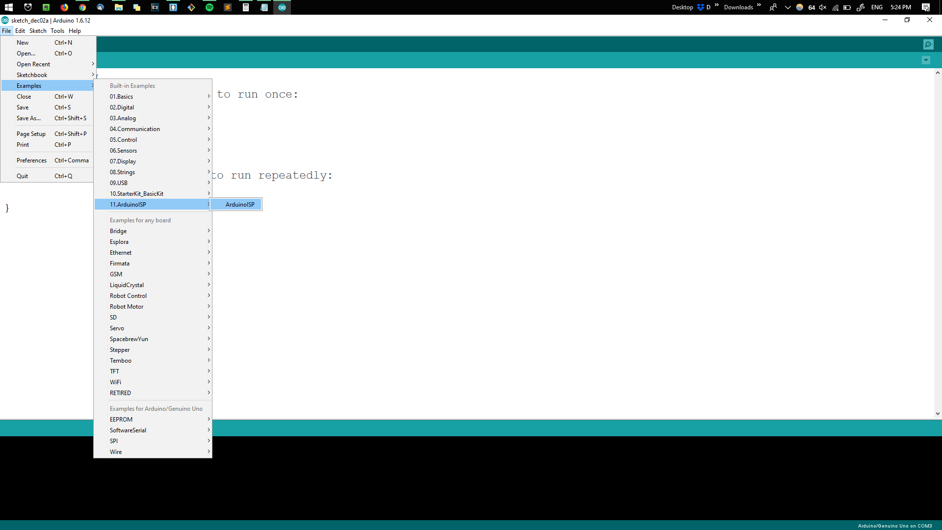
In this step, we will use an Arduino Uno to enable the FabIsp as a programmer. First using the Arduino IDE we will load the
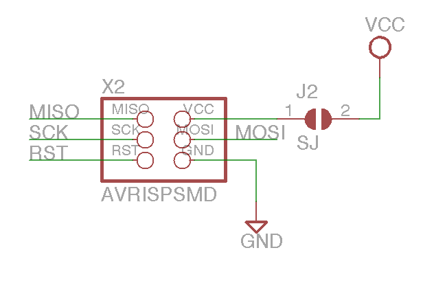
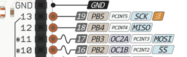
Since we will be communicating using the SPI (serial peripheral bus), it's important to notice the pins of FabISP, provided in the schematic, in order to connect the board correctly to the Arduino Uno.
As well as the pinage of the Arduino Uno.
The FabISP board is connected to both the computer which will be used to write the firmware and to the Arduino Uno using the SPI.
.jpg)
In order to write the firmware on to the FabISP, a Linux virtual machine is used. Once the Arduino Uno board is recognized by the virtual machine, we following the Linux OS instructions documented here.
First we make sure to install the necessary packages. We type each line one by one, by making sure to acknowledge the installation using the "y" key. Terminal lines for installing the packages:
sudo apt-get install flex byacc bison gcc libusb-dev avrdude
sudo apt-get install gcc-avr
sudo apt-get install avr-libc
sudo apt-get install libc6-dev
We change the path to a place where we can download the firmware. For instance the media directory:
cd /media
Download and unzip the firmware files:
wget http://academy.cba.mit.edu/classes/embedded_programming/firmware.zip
unzip firmware.zip
Once the firmware is unzipped, we navigate inside the firmware folder and open the Makefile using any text editor:
cd /fabISP_mac.0.8.2_firmware
nano Makefile
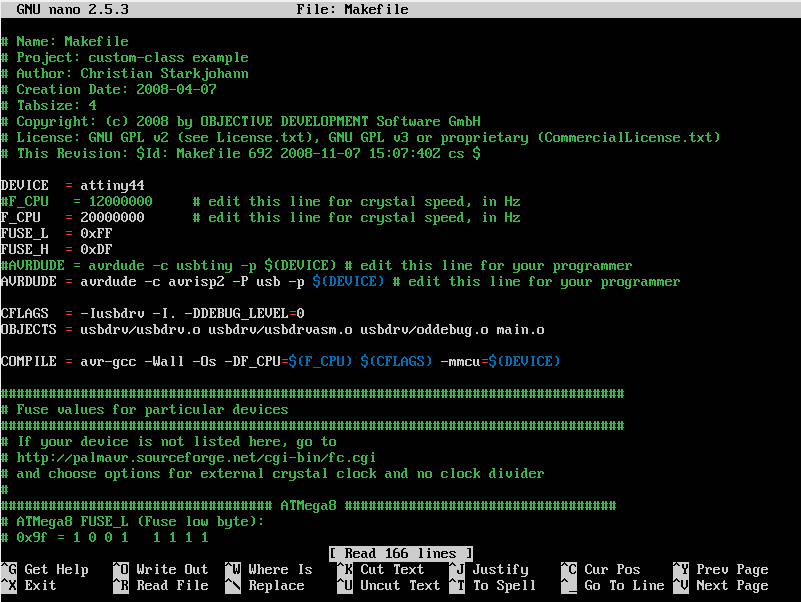
Crytical is to make some adjustments to the firmware file. The line:
AVRDUDE = avrdude -c avrisp2 -P usb -p $(DEVICE)
is exchanged to
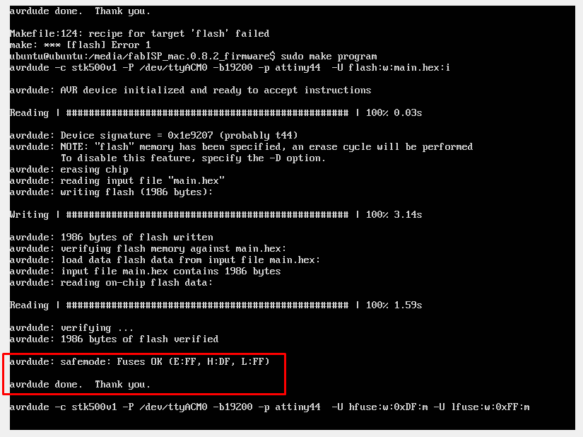
AVRDUDE = avrdude -c stk500v1 -P /dev/ttyACM0 -b19200 -p $(DEVICE)
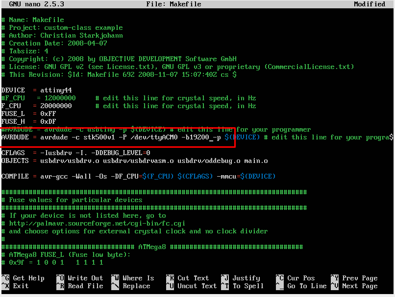
We save and exit the editor. What follows is a set of commands which will write the firmware onto our new board. These commands need to be executed one afte another. In case the execution results in anything else than the results provided here, make sure to double check the connections, physical and software.
make clean
make hex
make fuse
make program
As a result, we get a "done. Thank you." message.
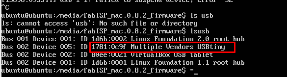
Finally we verify whether the board has been successfully programmed, simply running a check of plugged devices using:
ls usb
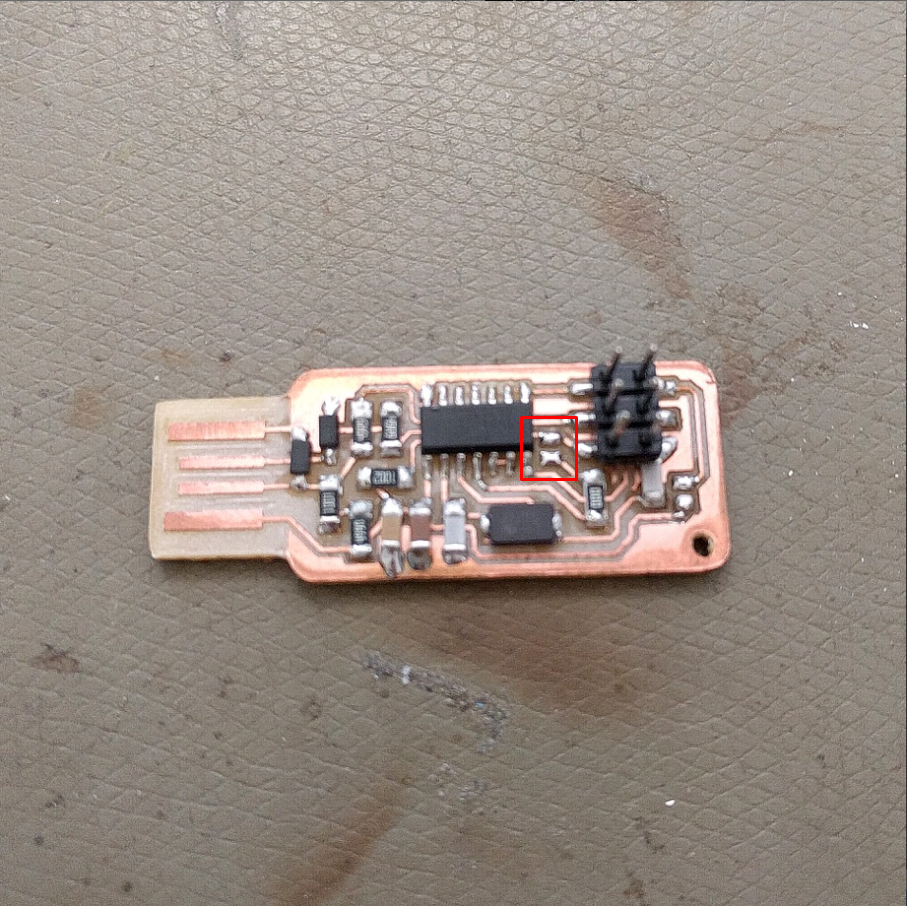
Desoldering the Bridge.
To make the board fully function, one last step is required. That is to desolder the bridge located closest to the microcontroller.
Aftermath
Creating an open-source board takes quite some time, effort and tinkering, however this allows repolicating boards and adopting new circuits in no time. In this session we recreated a board as well as program it using the Arduino IDE. Important is, after each step accomplished, to verify whether parts of the system are working well. Once all parts are working well, the whole assembly will function properly.
As a result, our FabISP will serve to program other future boards simply by using the SPI.