Input Devices.
Concept.
For this session, the concept is to explore some sensor devices in order to get some input data as a result.
My interest is behind tangible devices and how touch can influence/trigger other systems. For this purpose I decided to explore the capacitive touch sensor, which I intended to create on my own using the guidance and library of Capacitive Sensing Library.
Design Phase.
Using the breadboard, I built my circuit in order to test the capacitive sensor. For the input a flat piece of copper foil is used, which is sticked on a vinyl surface, as well as connected to the arduino input, by means of two resistors
To get a sensible output and visual clue whether the sensor works as intended, an LED is connected and lights up according to the simple
.jpg)
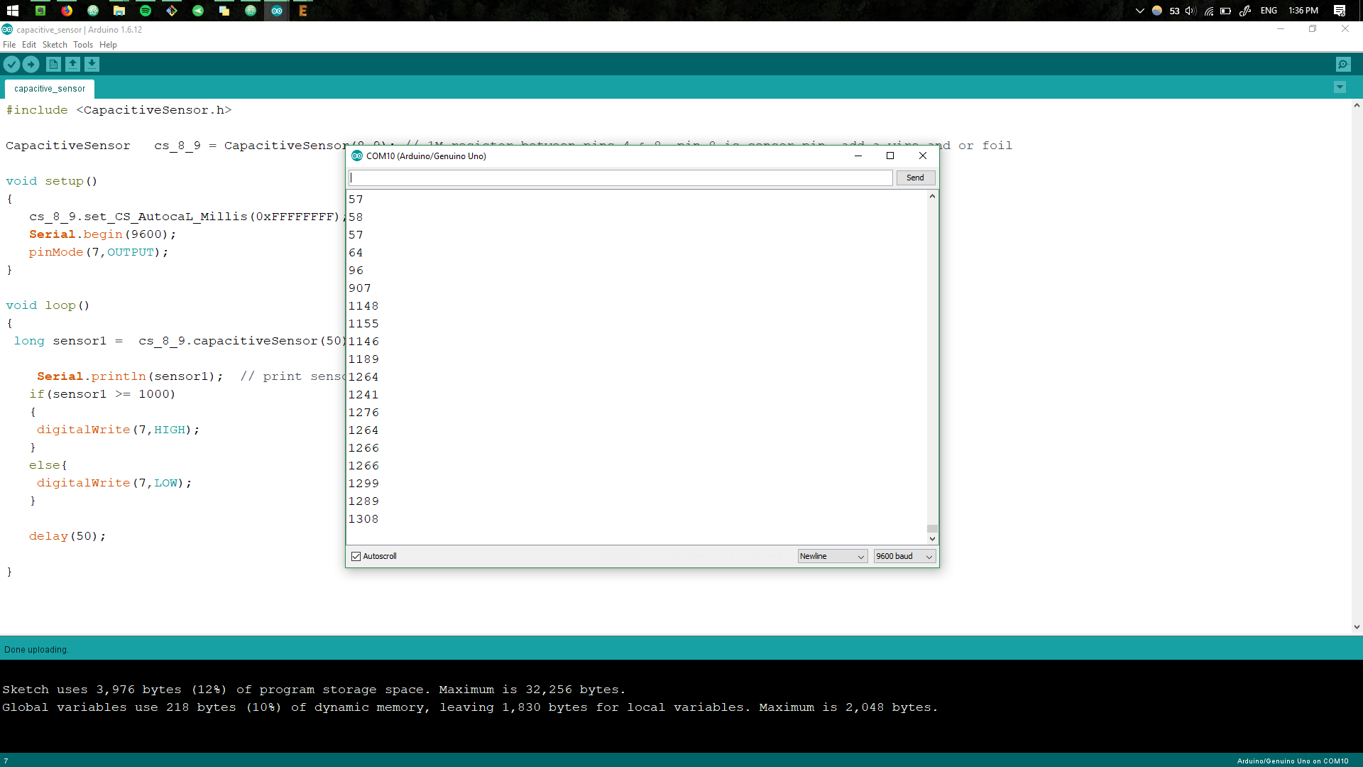
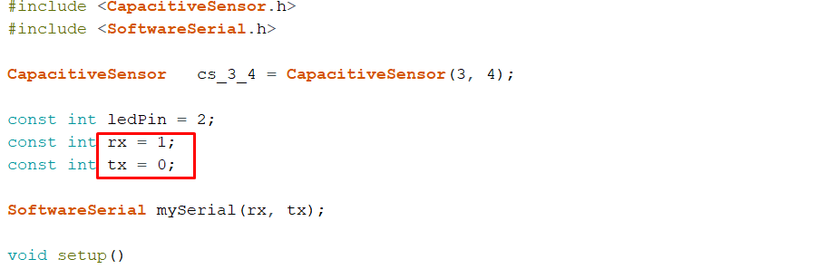
Using the Capacitive Sensing Library, the code defines the
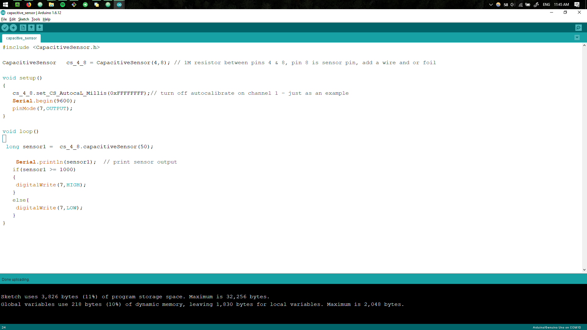
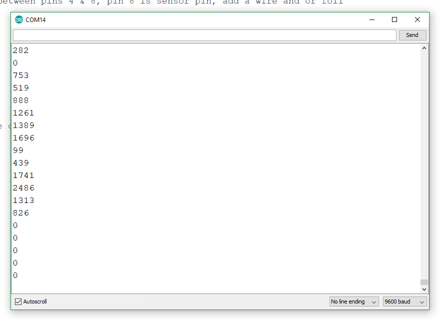
As a result, when the piece of coil is touched, the sensor triggers and lights up the LED and the values are displayed in the Serial Monitor.
The values differ depends how much of the capacitive foil is touched.
Circuit Design.
For the circuit design,
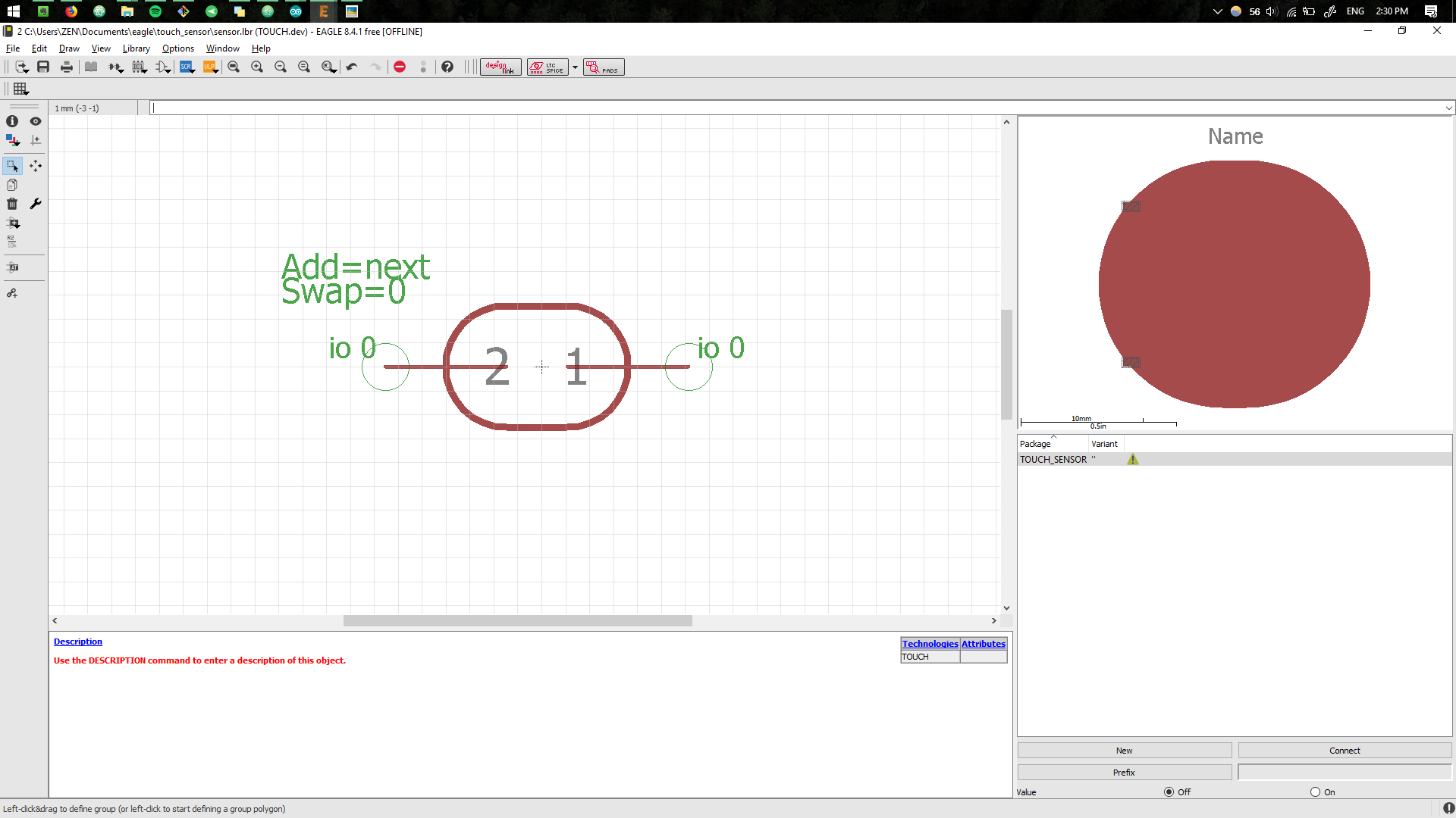
To do this, a new components needs to be created in Eagle by going to project folder, selecting
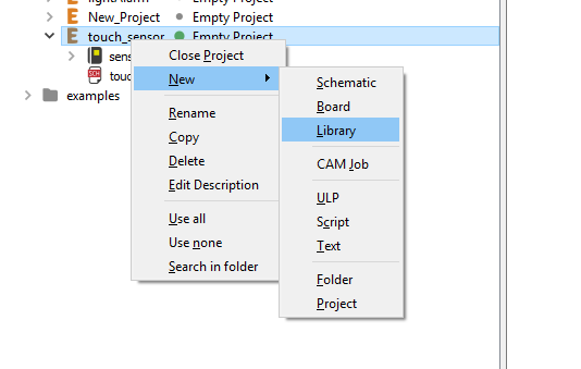
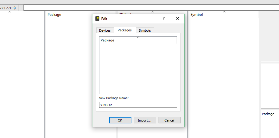
New package is then created.
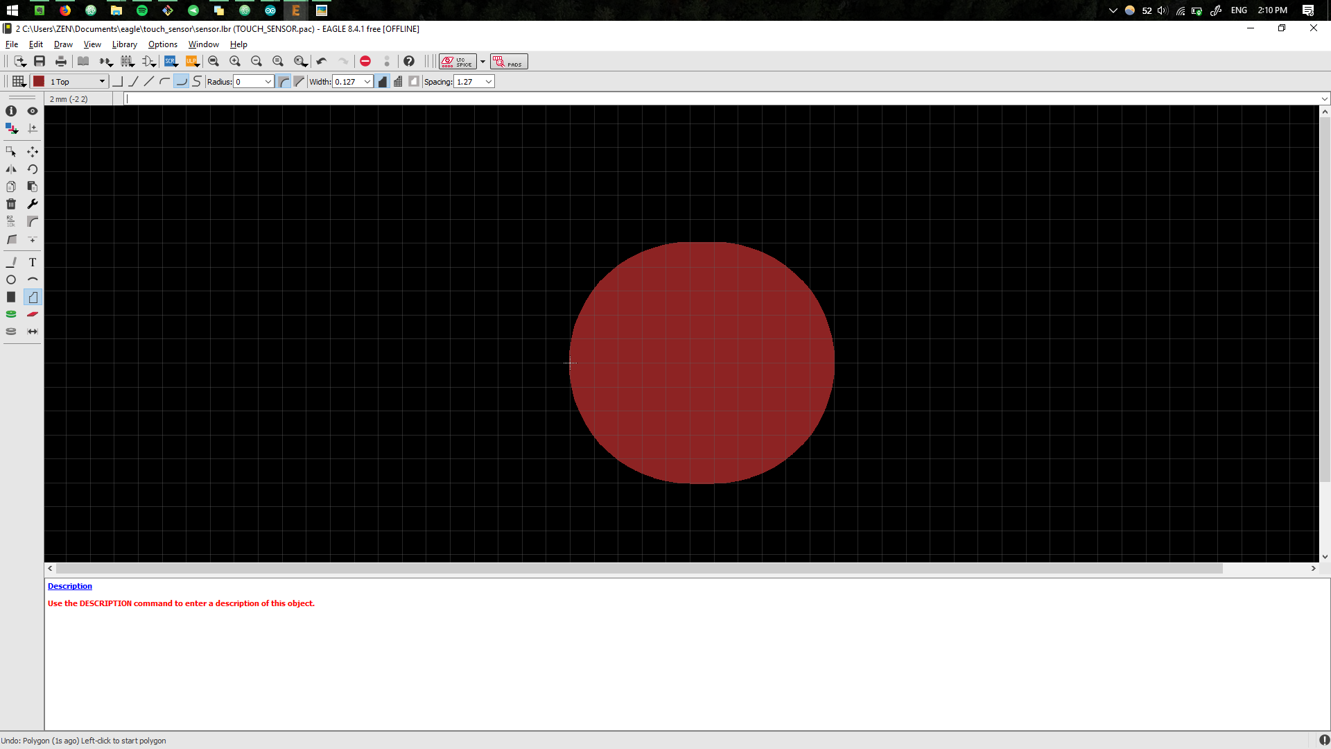
We draw the shape of the packed, in this instance it is a pad in a shape of the finger, having two inputs.
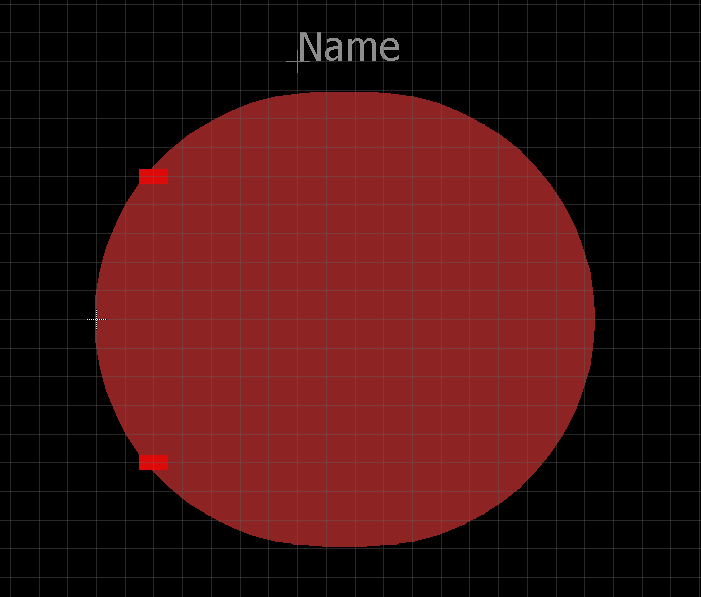
We also make sure to draw the symbol for it.
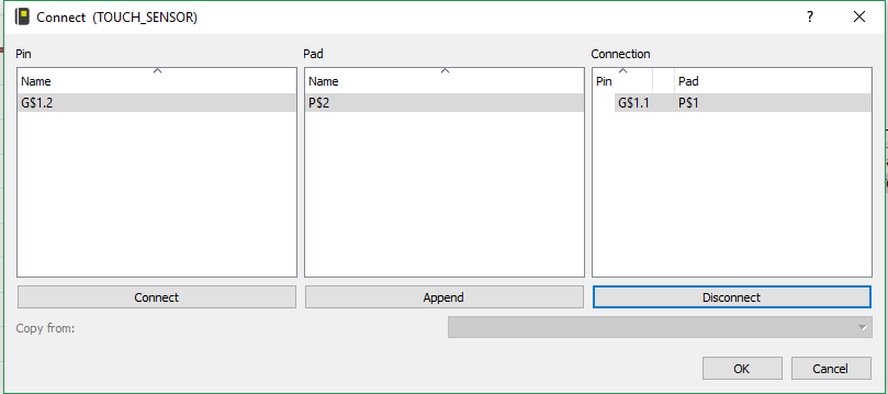
After we need to connect the symbol with the package, having matched the I/Os.
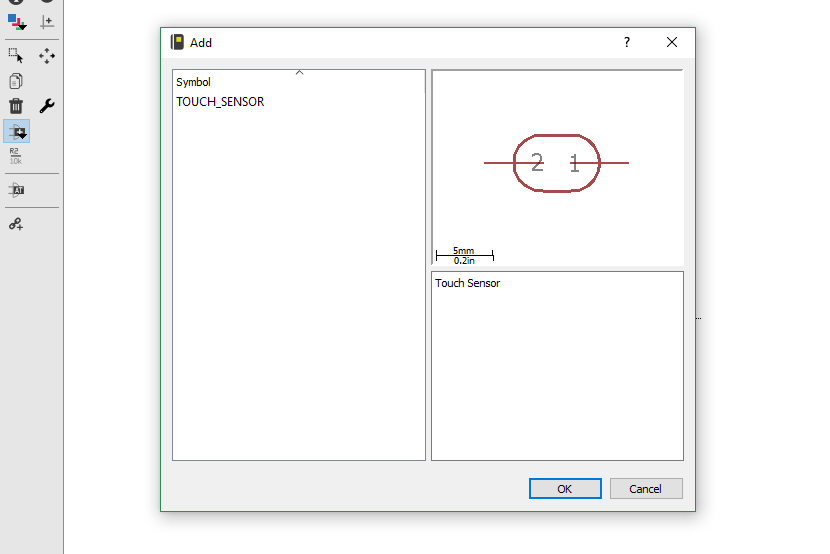
Now we can finally use it, by looking for the component in the library.
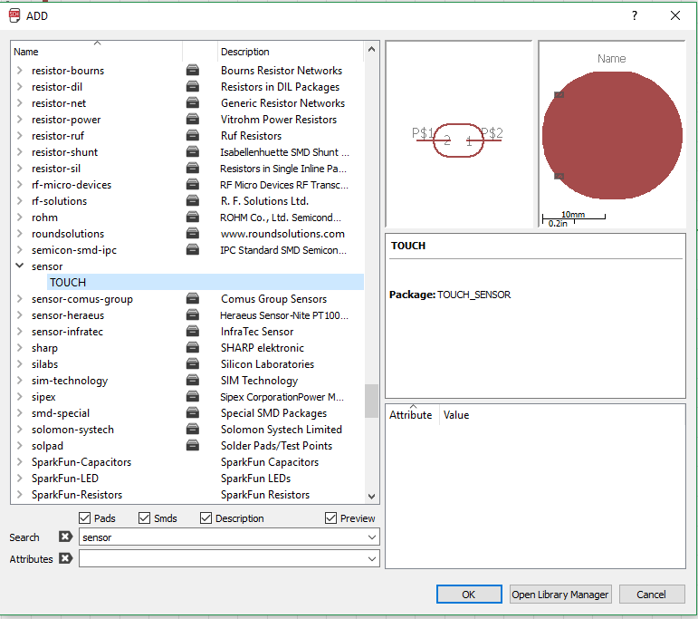
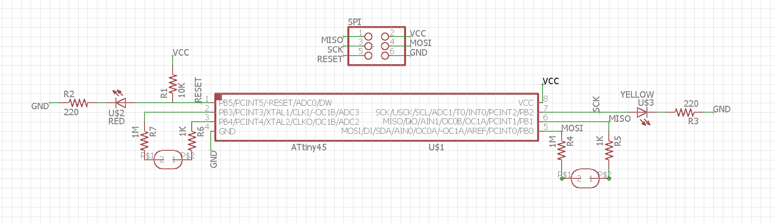
Using this component, similar to the Electronics Design week, we create the Schematic.
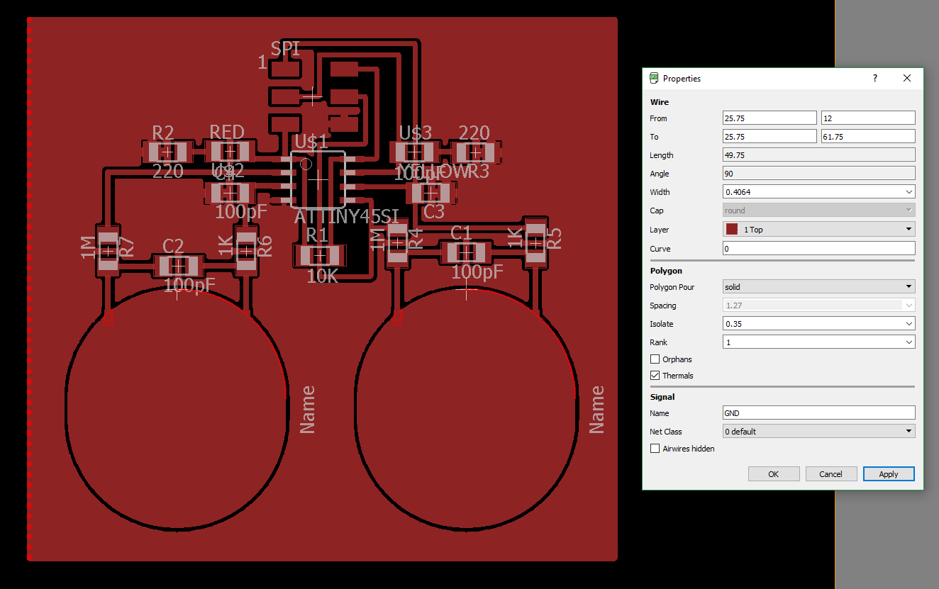
And the board layout.
Board Production.
The design is ran through the fabmodules.
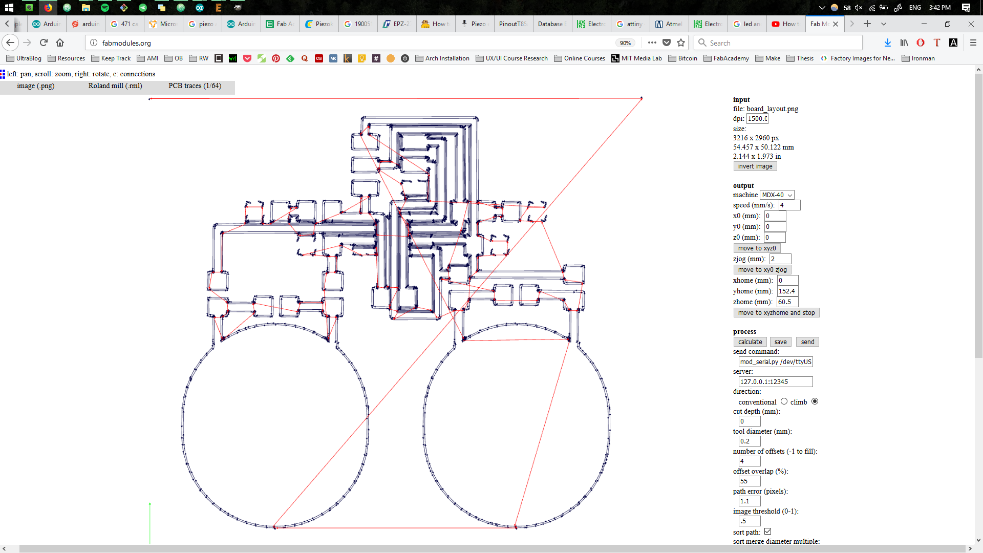
The board is produced.
.jpg)
.jpg)
The components are soldered to the board.
.jpg)
Programming the Board.
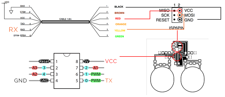
The board is connected through the SPI and the board is flashed first.
.jpg)
It is crytical to change the input pins of the board, in order to have the right pins directing the signal. As a result, playing a bit with the threshold and lowering it all the way to 400, the board lights up the LED.
Trying to read the data using SPI from the board was a bit tricky, for that
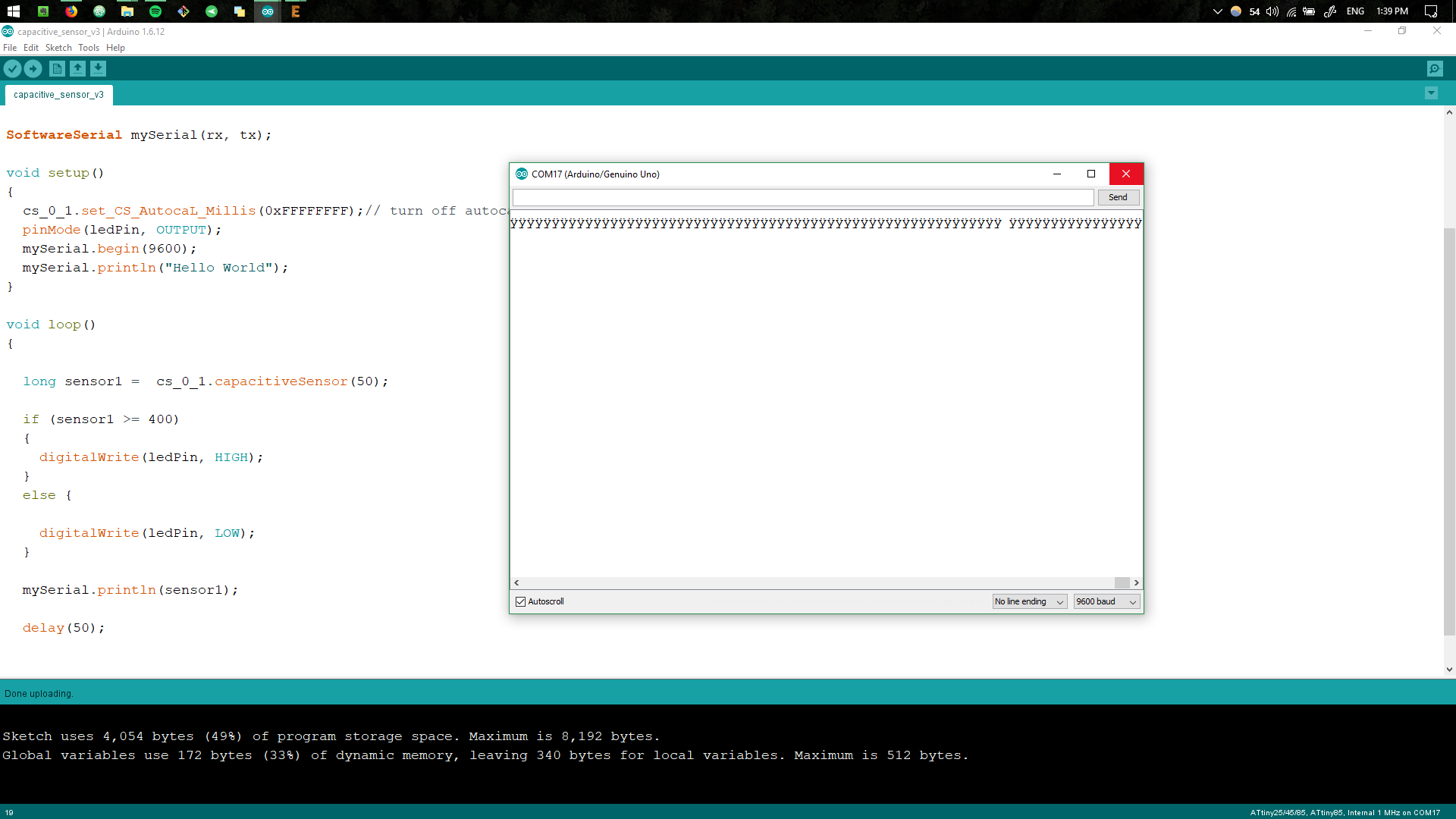
Reading the Data.
Reading the data by having an Arduino board as an intermediate device did not work well. This time we connect the board by using an FTDI cable, by reading the
By enabling the Serial Monitor of the Arduino IDE, we can receive the data as a result.