Mechanical Design.
Concept.
For this week the concept was to team up and build a maschine that can be replicable as well as As a machine concept, together with other teammates we decided to build a drawing machine, with interchangeable tools. Similar to a CNC, it would have three axis upon which the tool will travel, in the X, Y and Z axes. The overall documentation of the "BelissimoDraw" machine can be found on the following link.
This week's aim is to come up with the concept and the mechanical design of the machine. As a team, we have devide the overall work of the machine by using the three axes we have. Each team member takes one axix for design, mind is the Y axis and the bed located in between the base construction, which holds the X axis and the final tool holder, which travels in the Z axis.
Sketch.
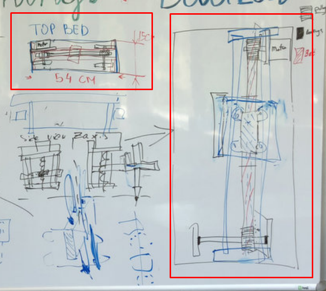
To illustrate the work, some sketches were created with the team members to illustrate the functionality and discuss the overral vision and work.
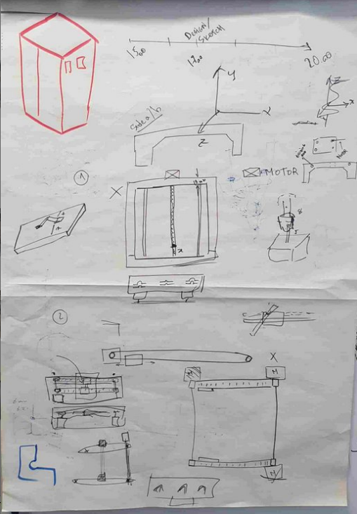
.jpg)
Having these drawn, we discussed the details, created some constraints and decided about the measurements.
Here is the overall sketch.
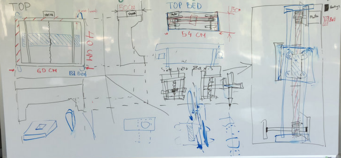
Here is the part that I focus on, the Y axis bed.
Mechanical Property.
The above sketch implies that the bed I intended to design will operate using one stepper motor with pulley on one side and connecting using a belt, a bearing on a rod on the other side. This way whenever the motor will rotate the pulley, it will drag the belt across it's whole construction. The belt will later on carrythe Z axis which will eventualy hold the tool.
The advantage of having a belt across the belt would allow a faster traveling speed, which would improve the overall design of the machine, by having a faster ability to sketch across the Y axis.
3D Design.
The design was accomplished using Fusion 360, most of the techniques used to come up with the model of the bed are described in the Week 2 and Week 3. The model helped to get a realistic view of the final bed once it will undergo the CNC process. Once the model was accomplished, some sizes were changed to achieve a good fitting with the other two components of the machince designed by my colleagues.
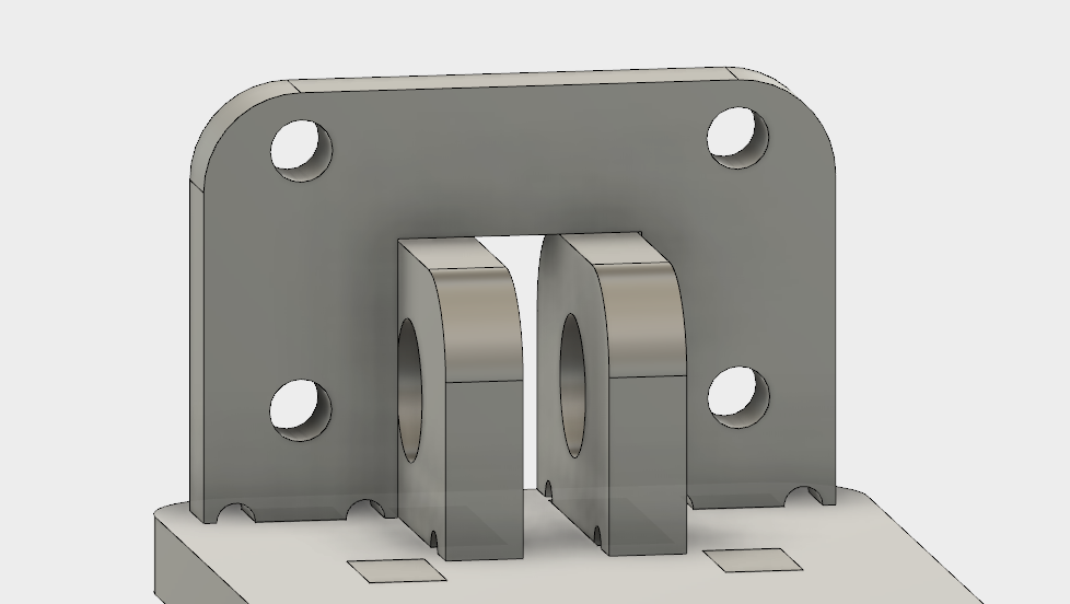
Here is the model from different angles that will be described briefly.
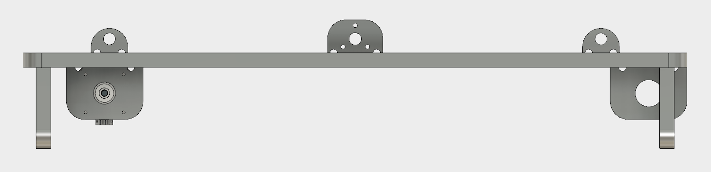
This is the side view of the bed. Top two holders that are simetrically displaced from each other are attached to the traveling rods which hold the entire construction. In between these rods we have one holder that is attached to the traveling unit of the Threaded Nema-17 Motor, which comes from the X-axis construction designed by my colleague.
The traveling unit is then attached using 4-M3 nuts and screws to the holder of the bed.
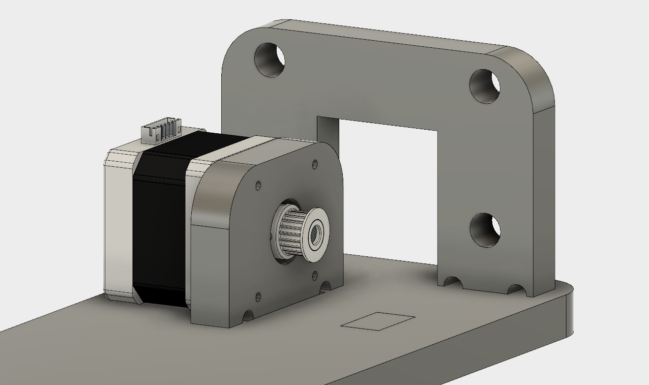
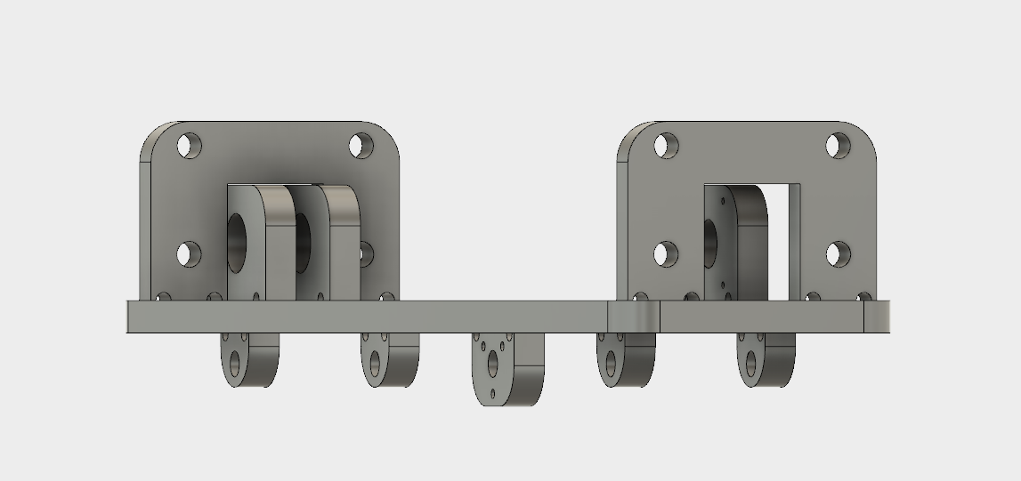
The motor itself is positioned horizontally, to lie flat on the bed and attached again using the 4-M3 screws to the perpendicullar holder, which is specifically designed to fit the motor using a throughwhole large enough to fit the pulley as well.
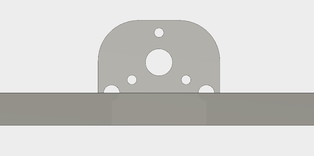
The far end construction has four holes to host another 2-4 potential traveling rods.
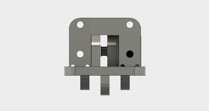
This is the view of the motor positioned from the side.
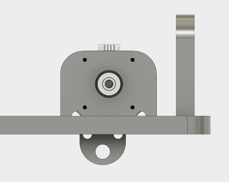
On the other hand side, we have the holders for the bearings, which in the middle passes a traveling rod with another bearing, this time for the traveling belt. This side also has at far edge a construction to hold two traveling rods.
Looking across the bed construction, we can imagine how the traveling belt passes in between and connects the two edges.
As a final view, we have the bed tilted.
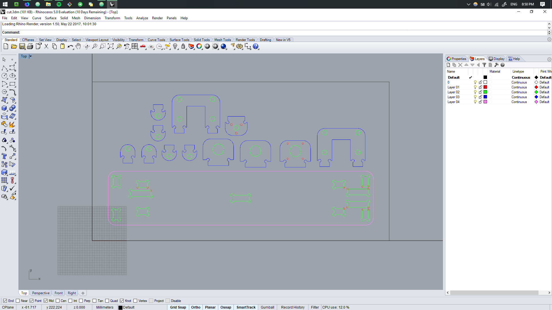
CNC Production.
Using Rhino 5 software, we import the DXF files generated using Fusion 360. To accomplish this see here.
As discussed in the Computer Controlled Machiningweek, the layers are separated using the priority.
.jpg)
Traveling path of the machine.
.jpg)
Gcode settings for the 6 mm tool.
.jpg)
Cuting process.
.jpg)
Final parts.
Assembly.
The parts are assembled to test the overall mechanics and test the compatibility of other parts.
.jpg)
As previously discussed, the motor is mounted by the means of
.jpg)
Once the motor is installed, the pulley is attached to it.
.jpg)
Each of the side holders, includes a bearing inside.
.jpg)
Through both of the bearings a rod is placed, which itelf holds another bearing. This would allow the belt to travel.
.jpg)
Finally the motor guide is installed in the middle by the use of the 4-M3 screws.
.jpg)
This is the final look of the bed.
System Troubleshoot.
Because of the good design, team communication and prior tests, we achieved a good fit of the overall system. Here is the final preview of how the bed is attached to the overall construction.
.jpg)
The final mechanical addition is attaching the traveling belt, which is achieved by first unscrewing the motor. While the motor is still inside the attaching wall, tilting it in the direction of the bearing. Now we place the belt and enclose it. Once the belt is well fixed, the motor is straightened to original position by screwing in the screws. This way the tension is achieved.
The overall bed construction is mounted on the two traveling rods that are simetrically distanced from the middle and a traveling unit that belongs to the X axis.
Here is a hand test of the system.