Output Devices.
Concept
The concept behind this week is to create an output device embedded on a board. My choice for this week's assignment was to implement something that fits towards the final project.
Since the intention behind my final project is to have a light output, the goal was to enable the microcontroller chip to use as few pinouts in order to provide a complex LED light output.
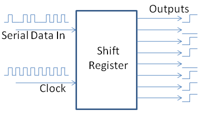
The concept which I intended to explore is using a SN74HC shift register . Using this chip one can control up to 8 different output pins using only 3 pins of the microcontroller.
Test of SN74HC Shift Register.
In order to properly understand the funcitonality of the register, I used the tutorial provided by the Arduino community.
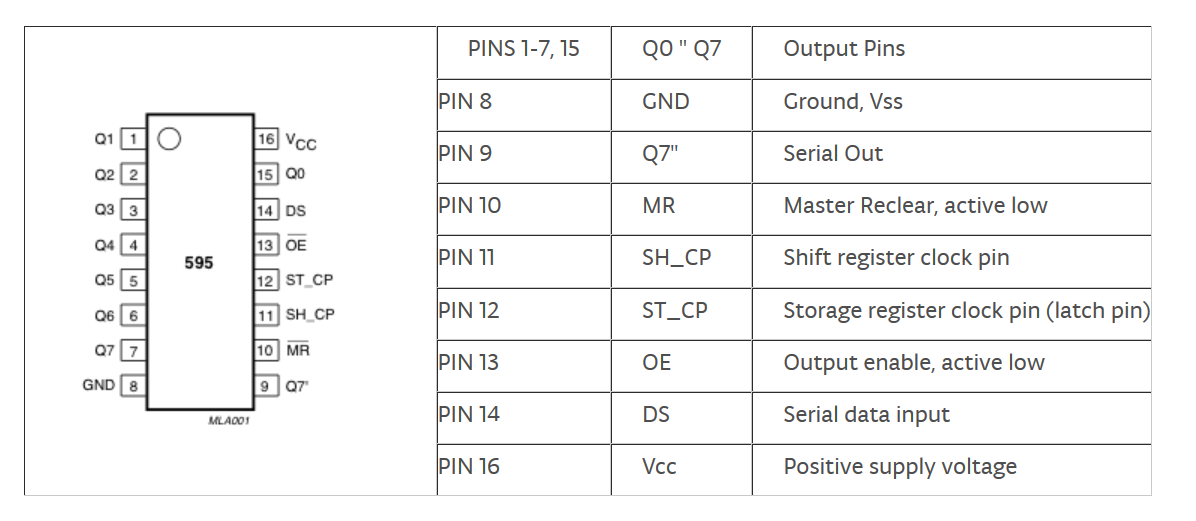
In essence, one the shift register works like a switching device, it has registries which can be programmed either as a HIGH or LOW. Using one data pin (DS) and two clock pins (SH_CP and ST_CP) it can send serial data to the output of its pins.
Breadboard Wiring.
The initial intention was to try out how the circuit works on the breadboard. In order to test the outputs, LED were chosen to get an imediate feedback of the device.
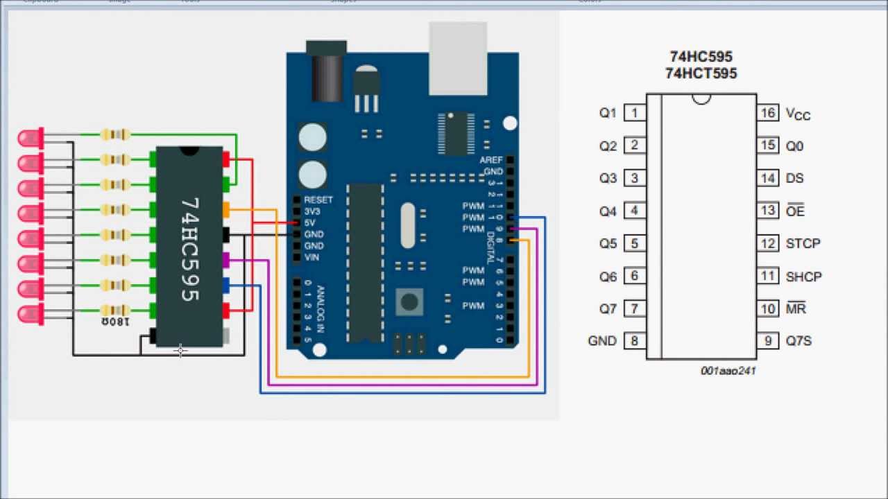
A similar circuit was recreated, this time by using only 3 LEDs just to test the functionality.
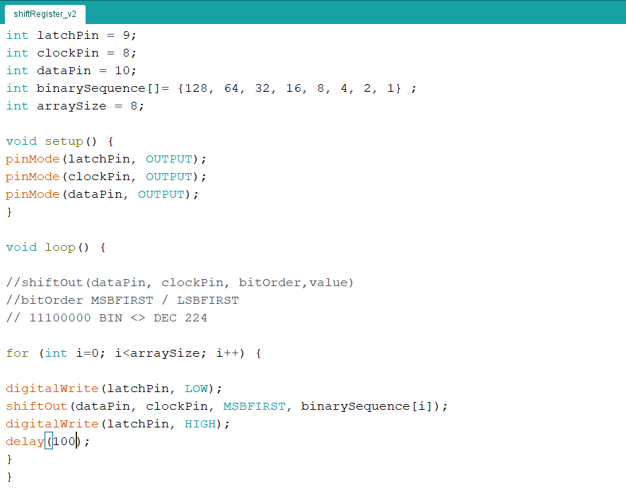
Arduino Code.
Once the board was wired, on the code level we have to define the different pins functionality.
                      int latchPin = 9; // Define the latch pin of 14/DS
                      int clockPin = 10; // Define the clock pin of 11/SH_CP
                      int dataPin = 8; // Define the data pin of 12/ST_CP
                      int binarySequence[]= {128, 64, 32} ; // A binary sequence to trigger the outputs.
                      int arraySize = 3; // Array used for while loop
Defining the pins procedure is done by tracing the wires from the Arduino board to the shift register chip.
In order to trigger shiftregister, we have a following sequence
//shiftOut(dataPin, clockPin, bitOrder,value)
This final
Having a loop of 128, 64, 32 will set in sequence first, second then third outputs as HIGH, by using the following loop.
                      for (int i=0; i<arraySize; i++) {
                      digitalWrite(latchPin, LOW);
                      shiftOut(dataPin, clockPin, MSBFIRST, binarySequence[i]);
                      digitalWrite(latchPin, HIGH);
                      delay(500);
                      }
In order to write a new set of registers inside the chip, setting the latchpin
Once we deploy our code to the Arduino IDE, we get the following output on the board.

The three LEDs light up in sequence.
Eagle Board.
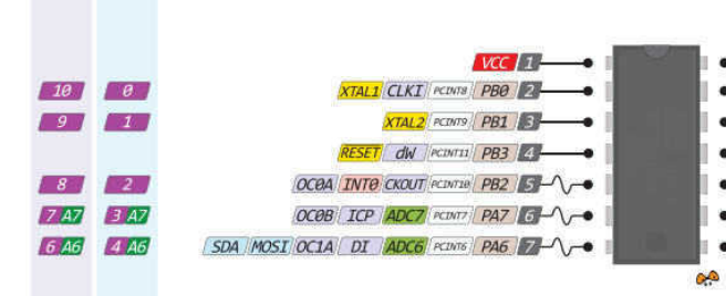
To correctly replicate the board in Eagle using Attiny44, we have to first consider the pinouts of the MCU. For that we need to use three digital pins of the MCU.
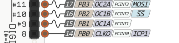
Pins 8,9,10 of the Arduino UNO correspong to the pins 2,3,5 of the Attin44.
Schematic.
As a resut we wire the Attiny44 to the SN74HC in the similar fashion as on the breadboard.
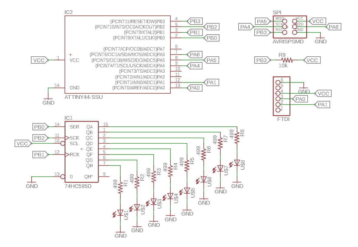
Here the circuit is extended to have up to 8 LED outputs.
Also the SPI and UART interfaces are added.
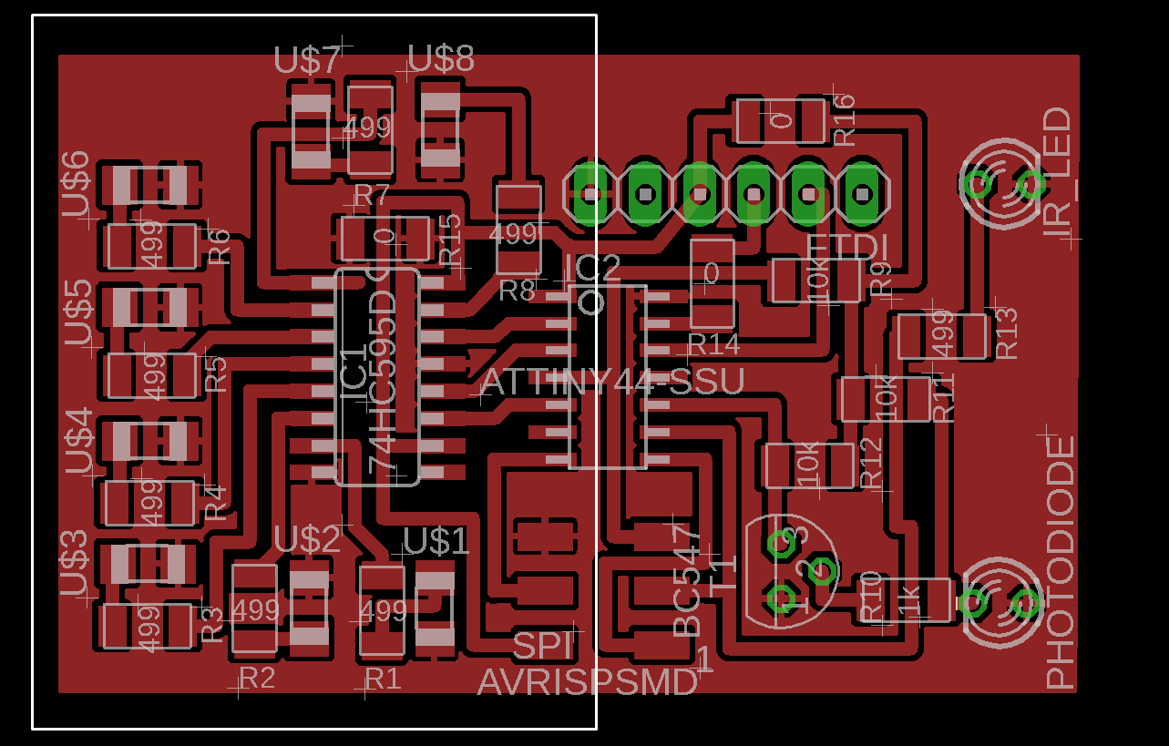
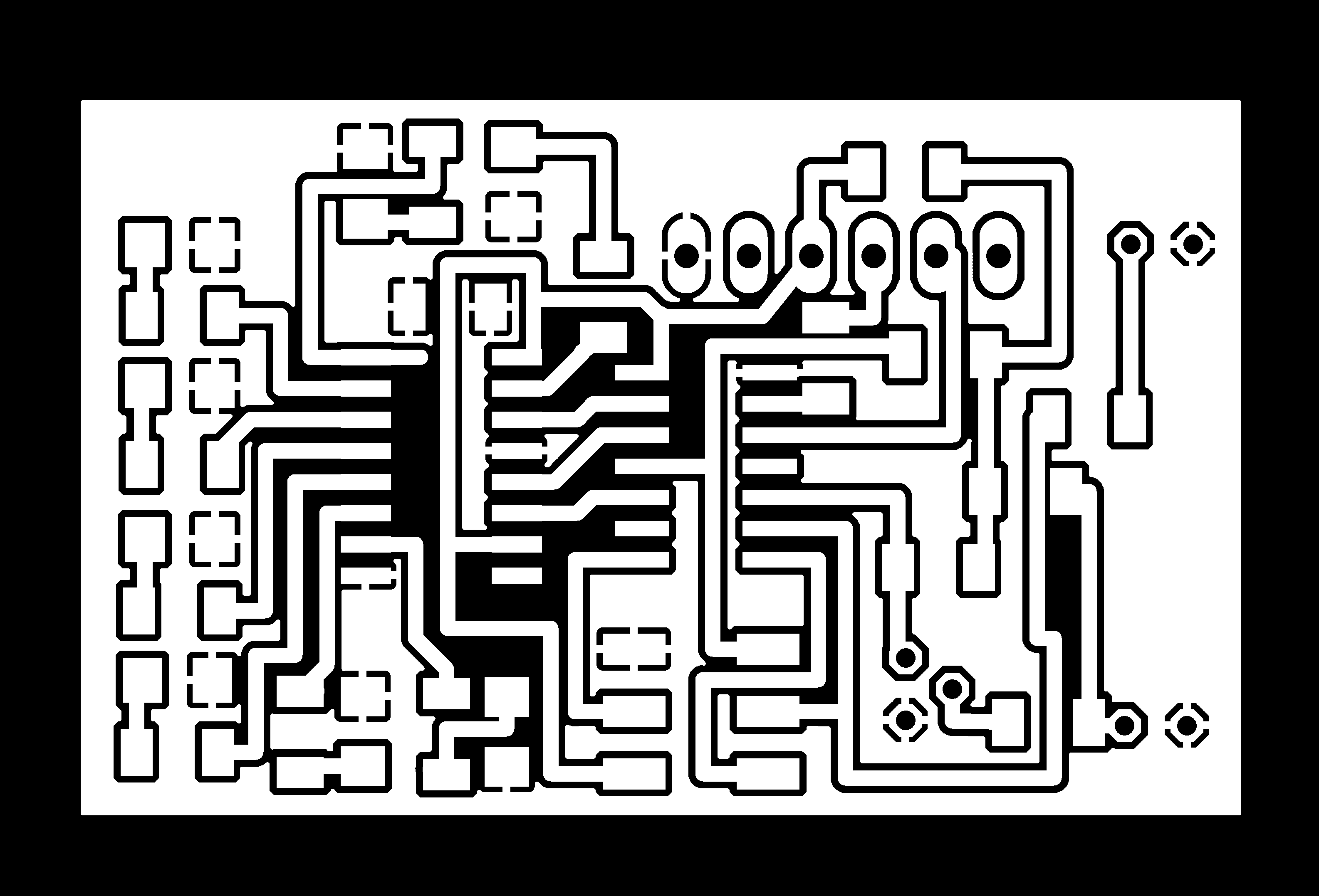
Board Layout.
Board layout is intended to be used also for the Networking week. The part in the white frame is relevant to the Output Devices, which includes:
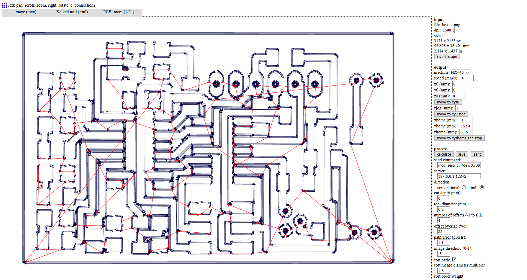
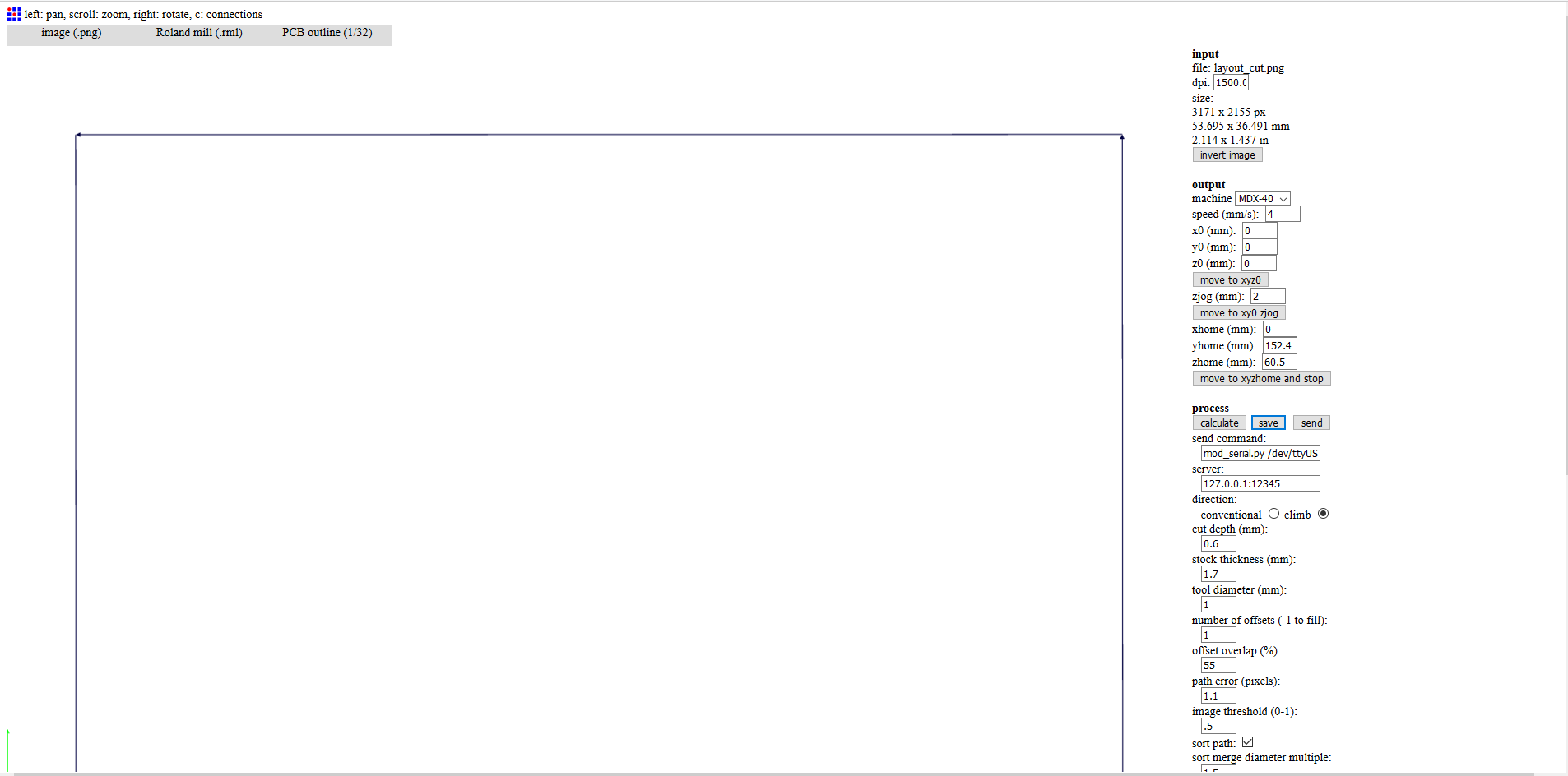
Production Files:
Layout.

Border cut.
Production.
Detailed production techniques are discussed in Electronics Production week.
.jpg)
.jpg)
.jpg)
.jpg)
Board Programming.
The same code is uploaded to the board of the MCU, this time the pin configuration is changed to correspond to the Attiny 44.
Datapin and clockpin are interchanged with pins 8 with 10.
The board is connected to the Arduino UNO for programming.
.jpg)
In order to succesfully program the board, the techniques are discussed in Electronics Production week.
First the Arduino UNO is programmed to act as Arduino ISP, then the proper board is configured in the menu, after which the code is deployed using theEnd Results.
Now we can light up the lights of led accordingly to our binarySequence indicated in the code.