Week 07: Electronics Design
In addition to Neil's lecture I enjoyed a great tutorial by our instructor, indicating functionality and function of the most important components to make the HelloWorld-Board:
|
This brought me to designing my first board in Eagle. Eagle's functionalities are quite comprehensible, offering an easier approach than Fusion360. To work the re-design assignment, it was necessary to download some libraries, each of which containing a set of up to hundreds of components as symbols, sketches, including the corresponding properties. Those libraries often come in ZIP files which need to be extracted, then copied into the lbr folder in Eagle. The libraries must be activated for use by opening the library manager, then clicking the Browse.. button and selecting the desired library from the catalog of the lbr folder.
Figure 01 displays the template that Neil provided for the re-design assignment. First step in the process was to copy this template into the logical layout as indicated in Figure 02. It took some guidance to identify the proper components from the libraries, but in the end it matched the template - at least logically.
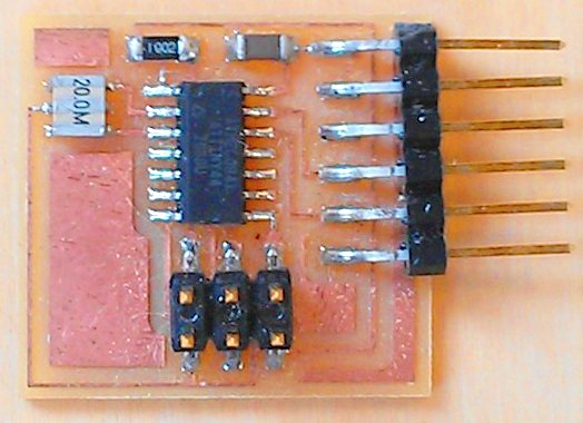 Fig.01: Board components from FabAcademy template. |
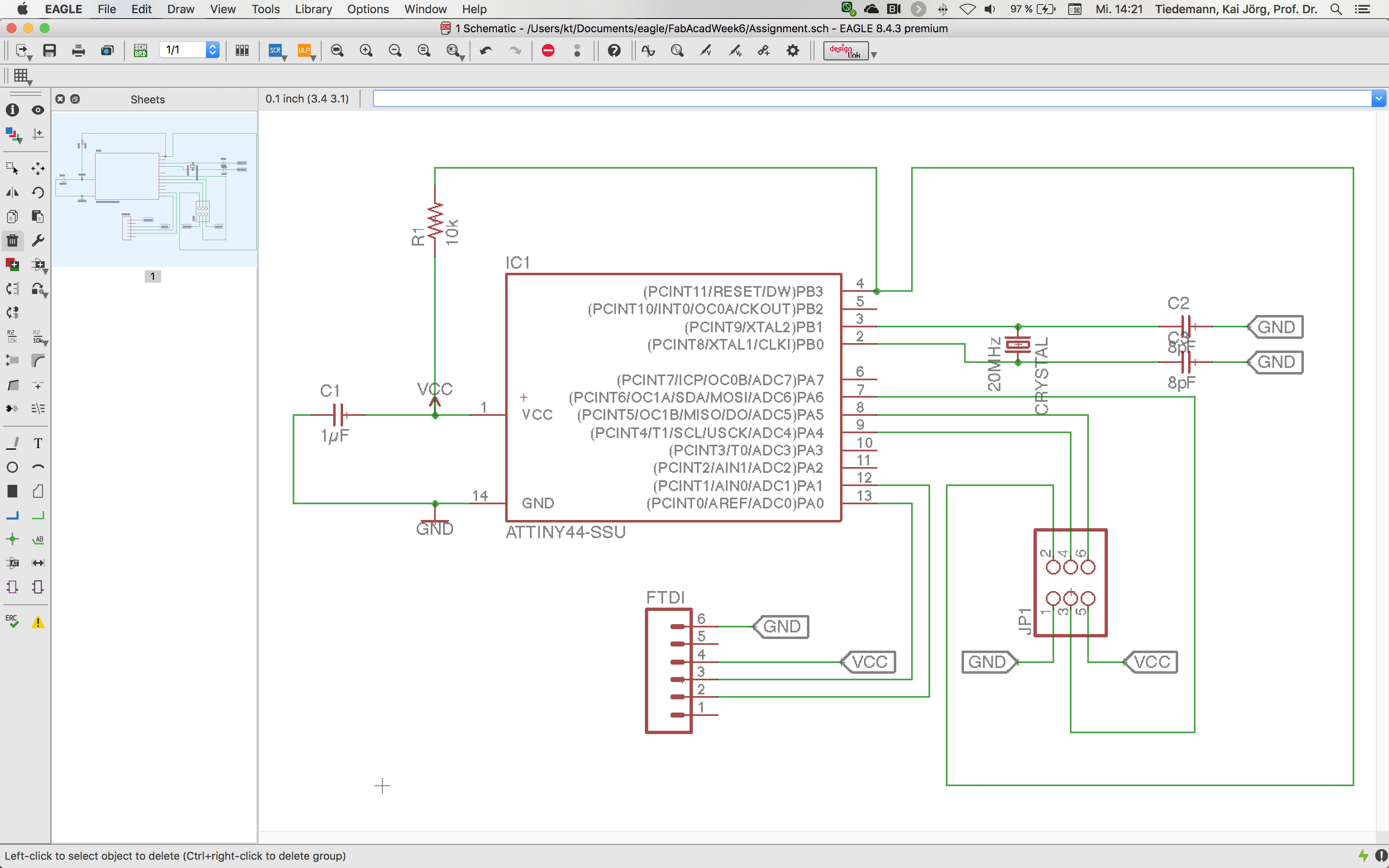 Fig.02: Eagle screenshot of step1 schematic view. |
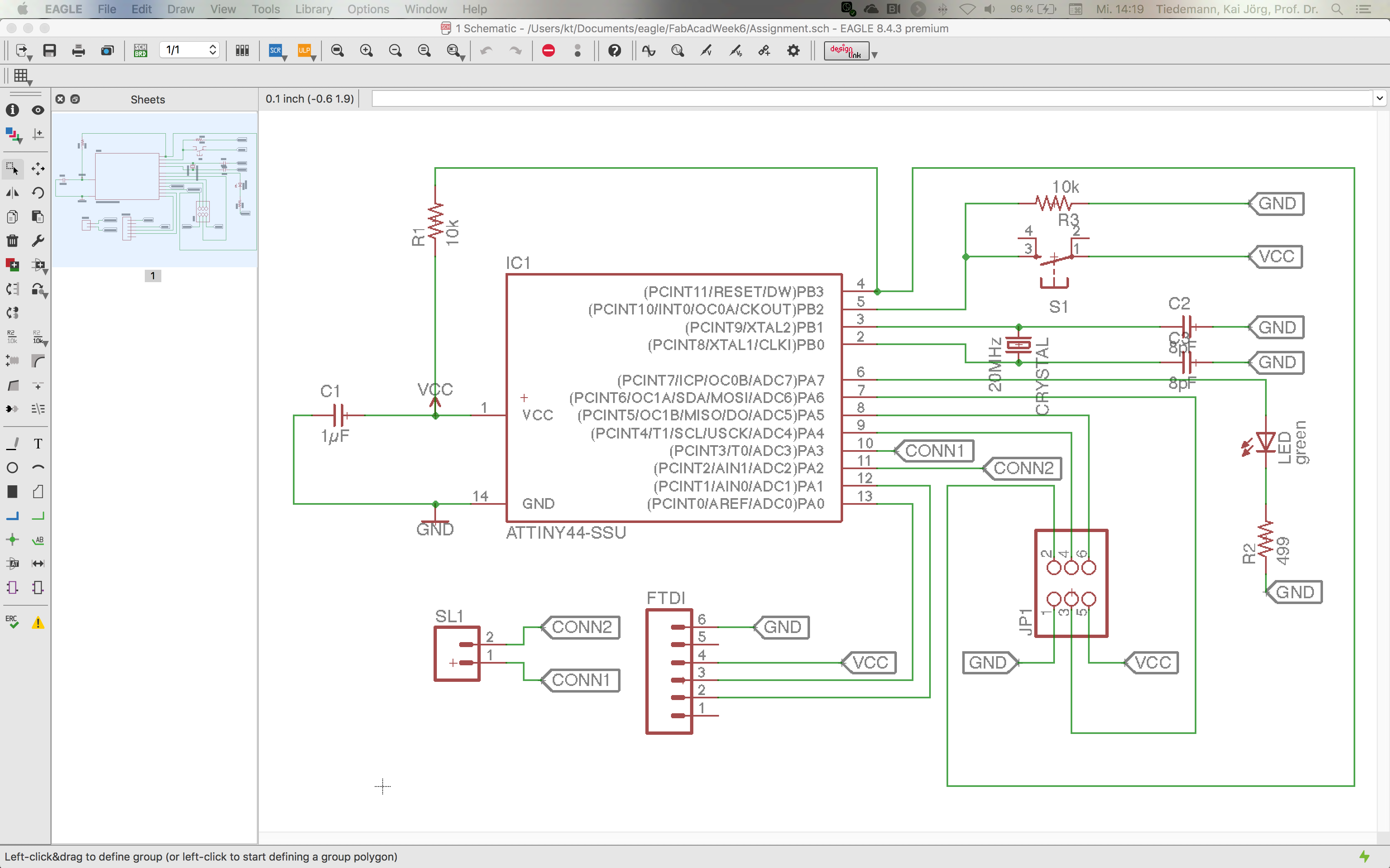
In addition to merely copying what the template demanded, the second part of the assignment was to add a button (marked as S1 in Figure 03) and a LED (marked as LED green in Figure 03) to the board. For enhanced functionality, I also added a connector to the board (marked as CONNECTOR in Figure 03). ...function of resistor for button..., ...function of resistor for LED...
Switching to board view started with importing the components to the board (Figure 04). I picked a GND-plate configuration and a trace width of 16. However, the first layout displayed in Figure 05 was a poor arrangement that did not allow for proper connections. Many re-arrangements later, I finally found a satisfying solution displayed in Figure 06.
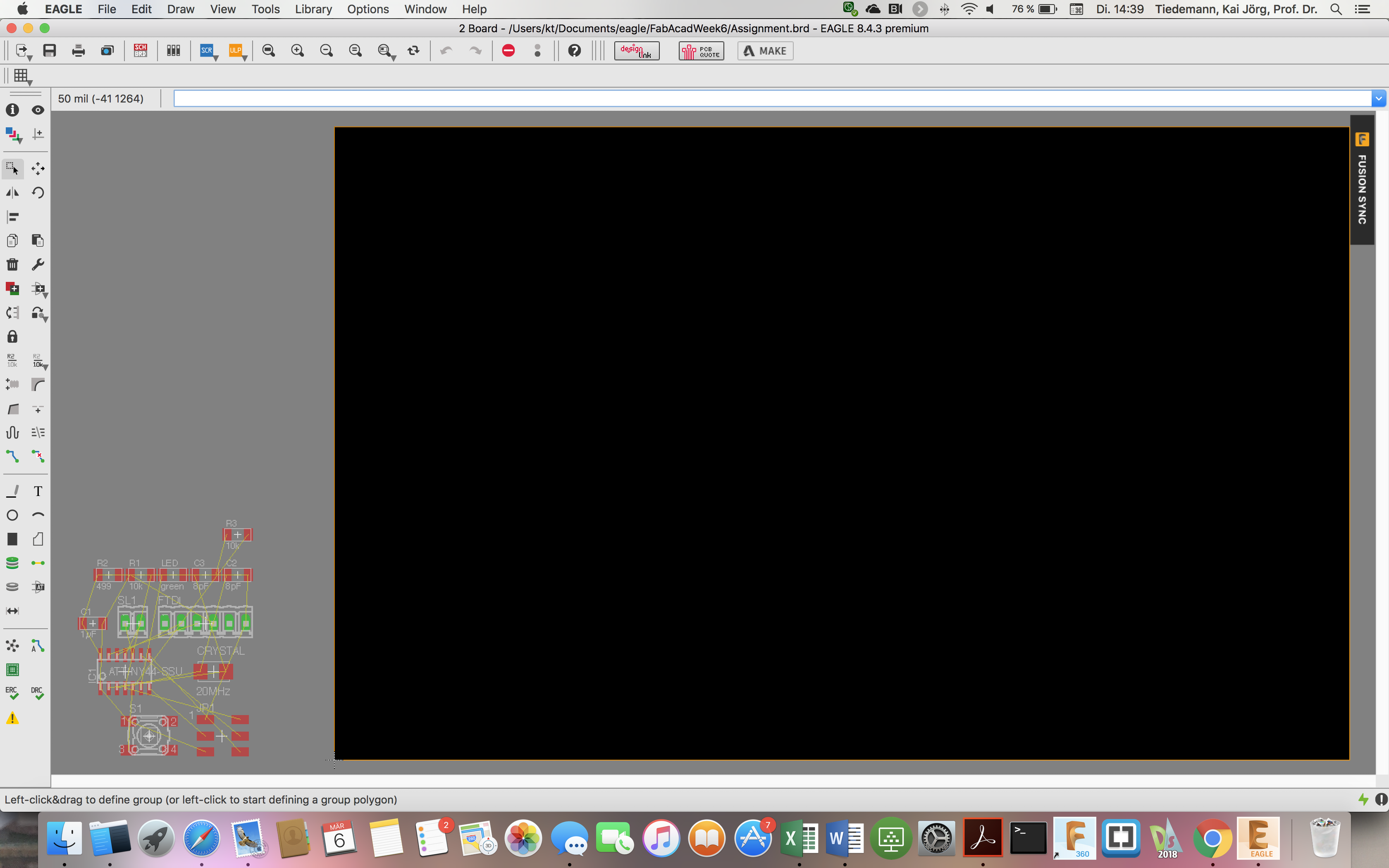 Fig.04: Import components from schematic to board view. |
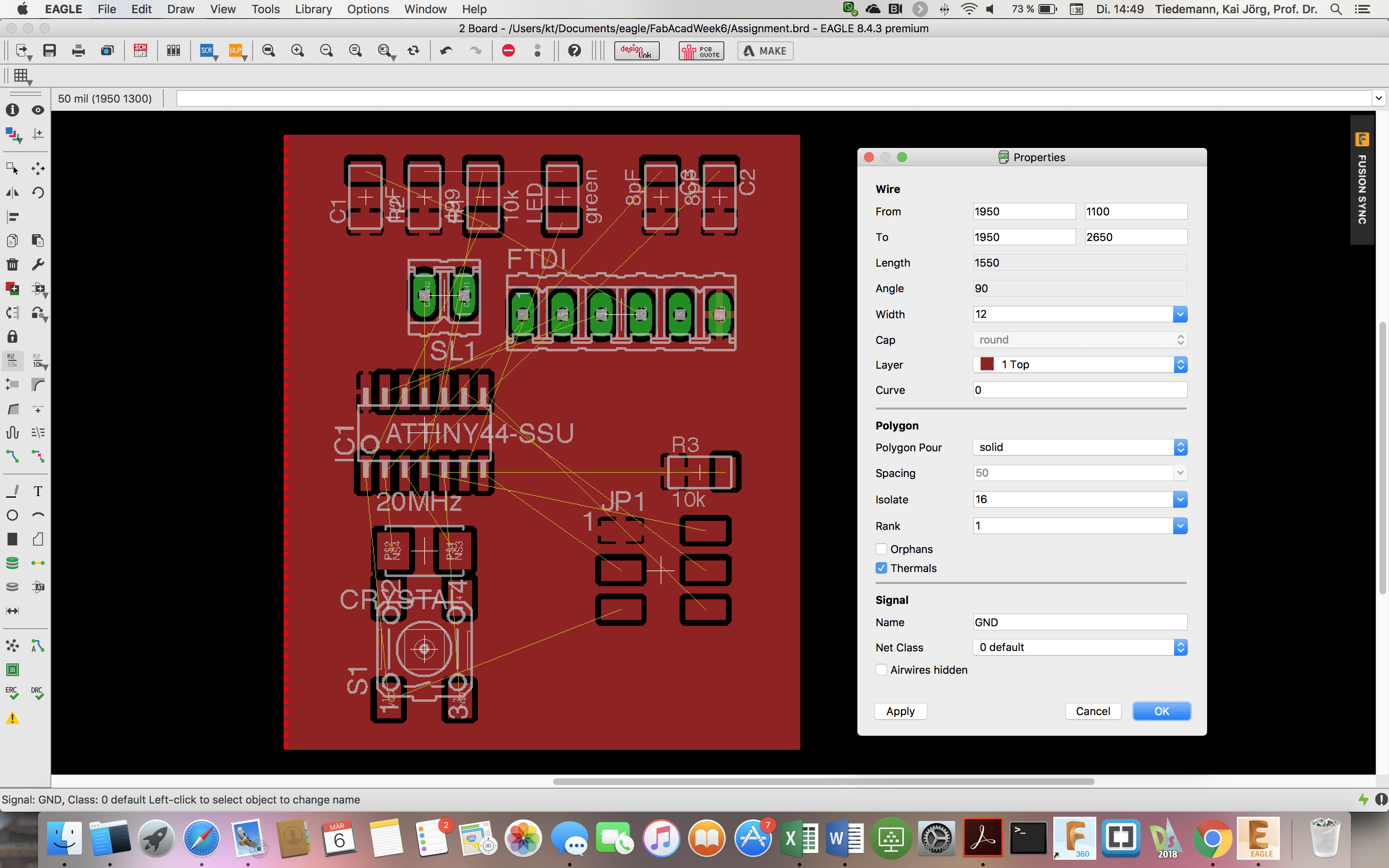 Fig.05: Eagle screenshot of first board layout. |
Fig.06: Eagle screenshot of final board layout. |