Contents
1. Objective
2. Interfacing with real world
3. Potentiometer
4. Ultrasonic
5. PCB board
6. Jostick
7. Download
1. Objective
You will learn how to interface the real world with MCUs, details about the difference between digital input and analogue input and how to read input from a potentiometer.
2. Interfacing with real world
Monitoring and controlling the real environment is commonly analogue in nature. To interface with the environment Analogue to Digital Conversion (ADC) and Digital to Analogue Conversion (DAC) are required.

In analogue to digital signal, the error is mainly due to sampling and quantisation.
3. Potentiometer
Problem: Write a program to get the reading of the potentiometer.
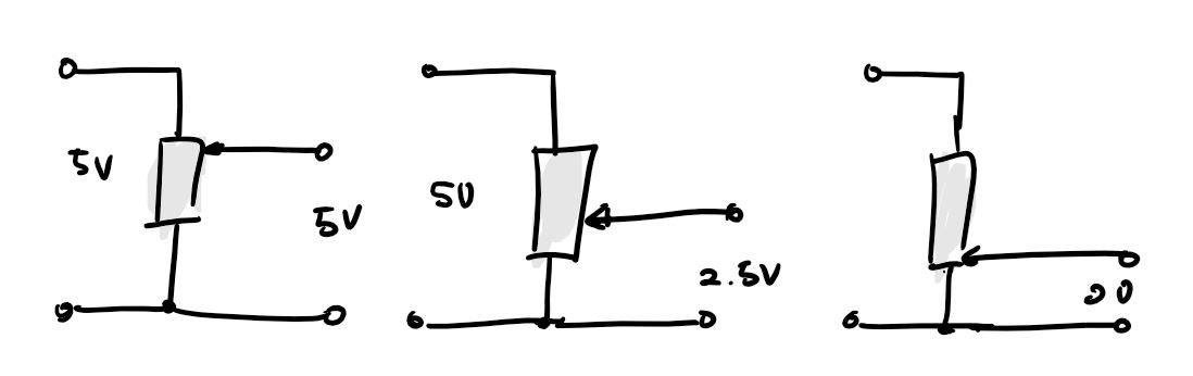
The output of a potentiometer that we are using is between 0 and 5 volt and it is manually adjustable. In this case, we do not have any choice but to use ADC to read the potentiometer output.
Let's write the programm.
First of all, initize all the inputs and outputs.
To read the value we will need 8 or 16 bit value, uint8_t poti_getValue8bit(void); or use double in Arduino IDE.
                                // Input pin

                                int button =0; // select the pin for the button


                                // Output pin

                                int ledPin1 = 11; // select the pin for the LED1

                                int ledPin2 = 12; // select the pin for the LED2

                                int ledPin3 = 13; // select the pin for the LED3


                                // Input Potentiometer

                                int sensorPin= A0; // select the pin for the potentiometer


                                double voltageValue;


                                void setup() {

                                 // put your setup code here, to run once:

                                 pinMode(ledPin1, OUTPUT);  // declare the ledPin as an OUTPUT

                                 pinMode(ledPin2, OUTPUT);  // declare the ledPin as an OUTPUT

                                 pinMode(ledPin3, OUTPUT);  // declare the ledPin as an OUTPUT

                                 pinMode(button, INPUT); // declare the button as an INPUT


                                    // initialize serial communication at 9600 bits per second:

                                    Serial.begin(9600);


                                }


                                void loop() {

                                    // read the input on analog pin 1:

                                    int sensorValue = analogRead(sensorPin);

                                    voltageValue = ((double)sensorValue)/1023*5;

                                    // print out the value you read:

                                    //Serial.print("SensorValue=");

                                    //Serial.println (sensorValue);

                                    Serial.print("voltageValue=");

                                    Serial.println (voltageValue);

                                    delay(100);


                                 if ((voltageValue<1.66))//

                                  digitalWrite(ledPin1, HIGH);  // turn LED ON

                                 else

                                      digitalWrite(ledPin1, LOW);  // turn LED OFF


                                 if((voltageValue>1.66)&&(voltageValue<3.32))//

                                  digitalWrite(ledPin2, HIGH);  // turn LED ON

                                 else

                                      digitalWrite(ledPin2, LOW);  // turn LED OFF


                                 if ((voltageValue>3.32)&&(voltageValue<=5))

                                  digitalWrite(ledPin3, HIGH);  // turn LED ON

                                 else

                                    digitalWrite(ledPin3, LOW);  // turn LED OFF


                                }
Afterward read the analog in sensor Pin and then calculate the voltage value.
To run this code I used a Satshakit-128 board.
Regarding the input of the potentiometer turn on the led as the potentiometer is turned the led is leveled up.
4. Ultrasonic
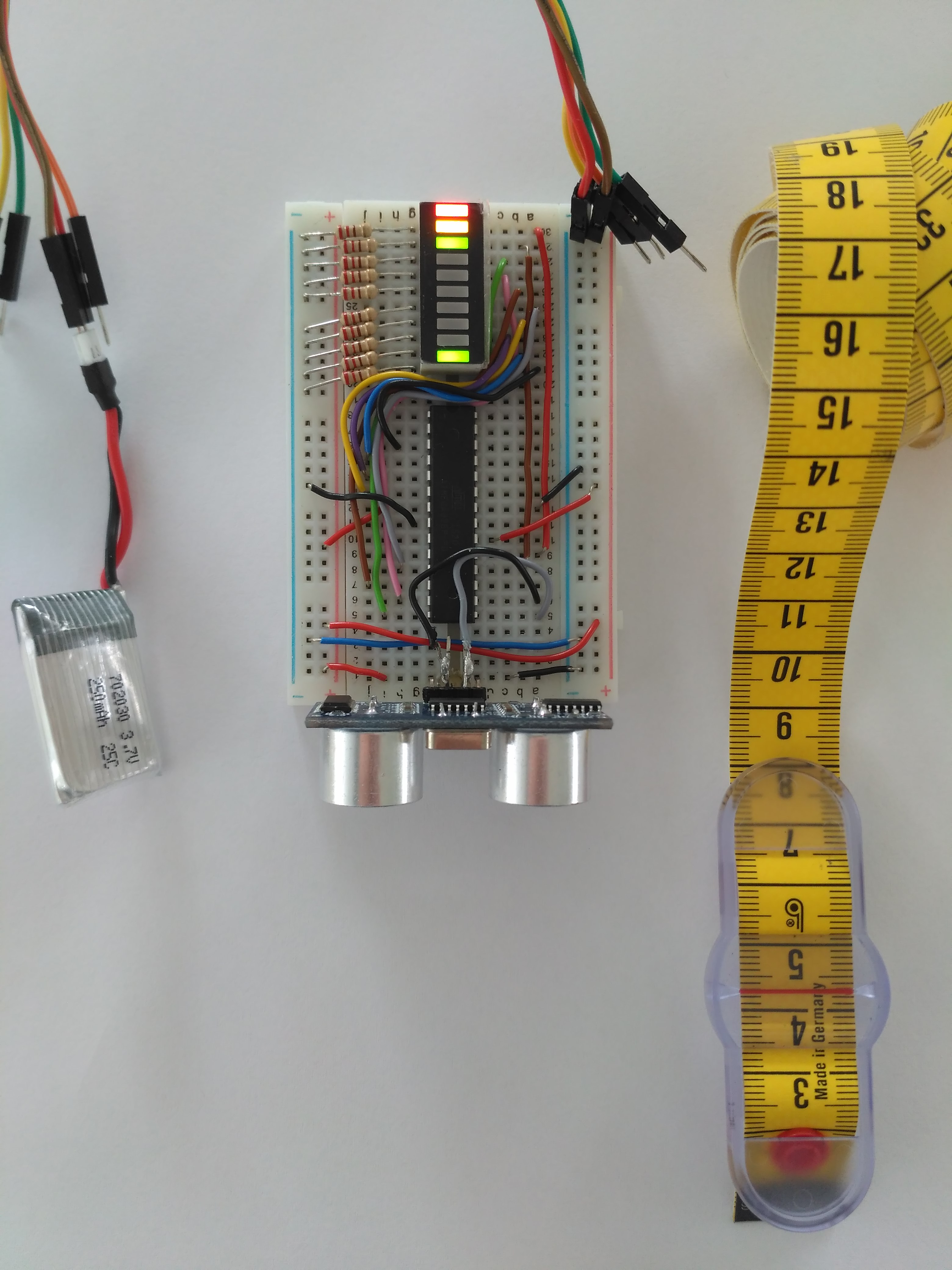
Ultrasonic to measure distance with an led bars to indicate how long does it measures.
Operation Principles
Piezoelectric devices are commonly used in ultrasonic sensors which emit high frequency (above 20kHz) sound pulses at regular intervals. The reflection from nearby object is obtained by a receiver and then based on the speed of sound the flight time can be calculated.
Physics : active sensor, works on time of flight
Advantages : Range between 12 cm up to 5 m, inexpensive (4Euro), small
Disadvantages : Specular reflection, crosstalk, foreshortening, high power consumption
Connect the triger pin and echo pin! The pulse a sound wave and wait until the sound is recieved, the interval time will be calculated to measure the distance.
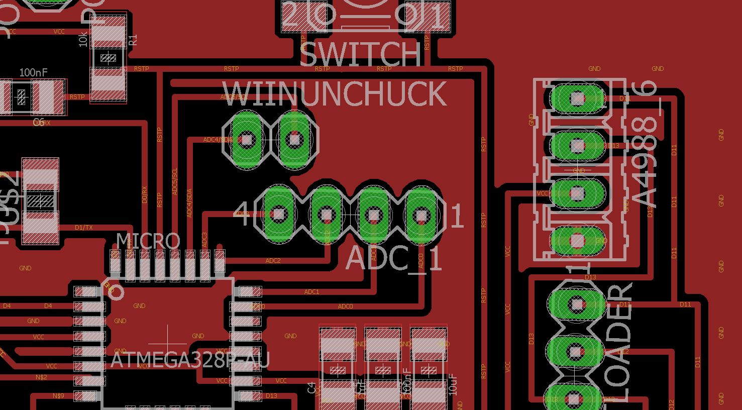
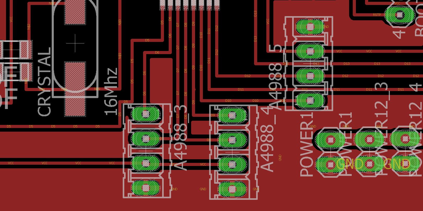
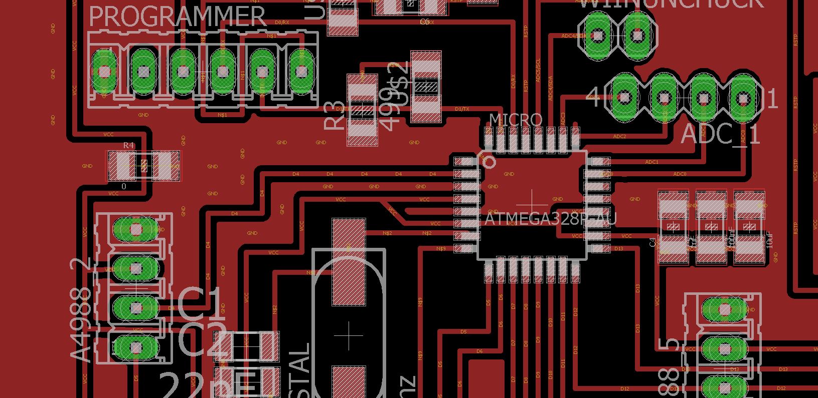
5. PCB board
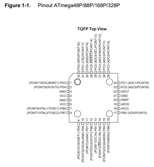
This is the pinout from the datasheet of ATmega 328P
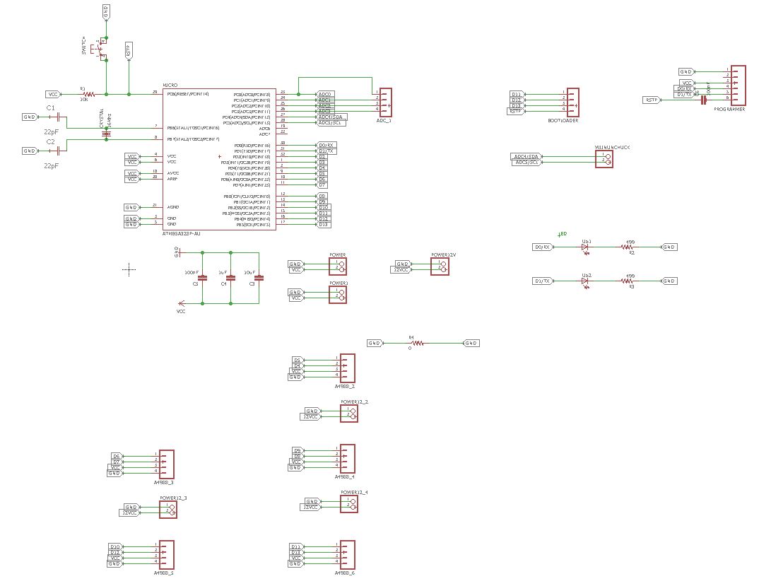
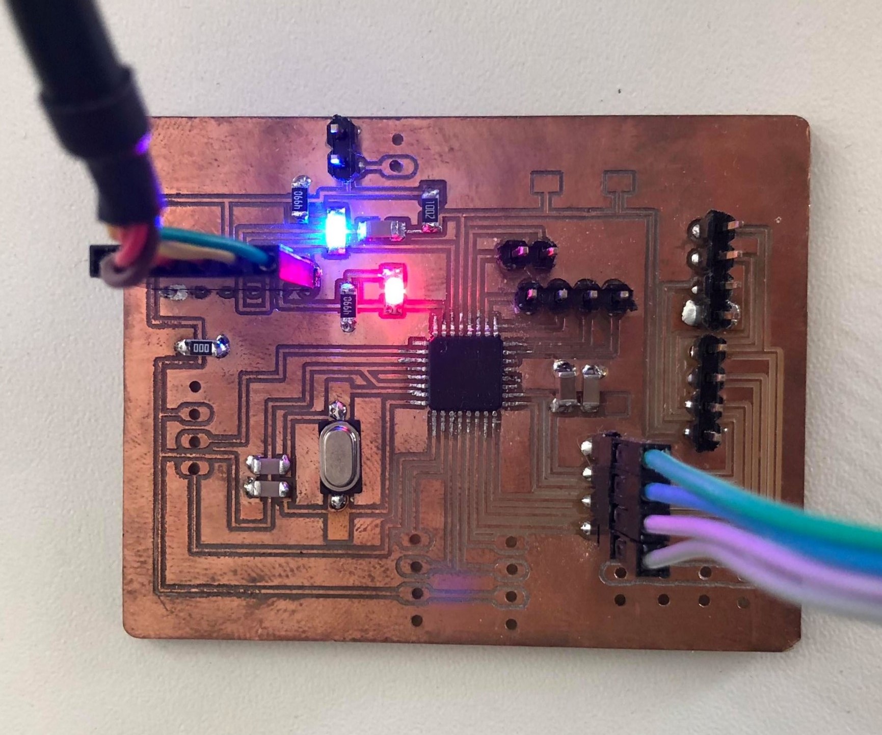
This is the main board for my final project that can be connected easily to a FTDI and 5 stepper motor driver connections.
The modifications are adding FTDI connections, pins for bootloading the microcontroller and 5 stepper motor driver connections
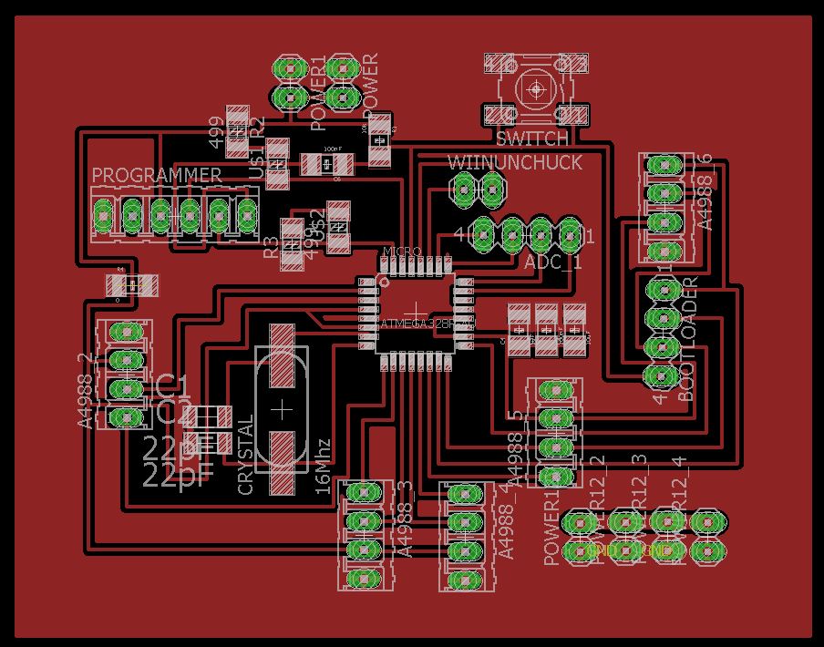
This is the board!
6. Joystick
This week, I was trying to program a joystick. First of all, I was trying to get the input on the potentiometers in the joystick in x and y direction and by that I used a state machine to idetinfy where the user switch the joystick.
I thought that the original SatshaKit will fit nicely. It will create a mess of cable, therefore from the satshakit I modified the pins location so it can be connected directly to the ISP and easily connect to the joystick and a stepper motor driver for next week assignment.
Code :
                                // input pins

                                const byte Xin      = A0;   // X input connected to A0

                                const byte Yin      = A1;   // Y input connected to A1

                                const byte Buttonin = 11;    // pushbuttom input connected to Digital pin 7


                                // output pins (only if necessary)

                                int ledPinBlue  = 0;        // select the pin for the blue LED PB0

                                int ledPinRed   = 1;        // select the pin for the red LED  PB1


                                // state machine

                                int state       = 0;


                                //threshold because of physical limitation 533 centre of joystick at x axis

                                const int THRESHOLD_LOW_X   = 523;

                                const int THRESHOLD_HIGH_X  = 543;


                                //threshold because of physical limitation 522 centre of joystick at y axis

                                const int THRESHOLD_LOW_Y   = 512;

                                const int THRESHOLD_HIGH_Y  = 532;


                                // joystick value

                                int sensorValuex,sensorValuey, buttonState;


                                void setup() {

                                   // put your setup code here, to run once:

                                   Serial.begin(9600);               // initialize serial communication


                                   //Input

                                   pinMode (Buttonin, INPUT_PULLUP); // internal pull up resistor

                                   pinMode (Xin, INPUT);             // initialize Xin as INPUT

                                   pinMode (Yin, INPUT);             // initialize YZin as INPUT


                                   //Output

                                   pinMode(ledPinBlue, OUTPUT);      // declare the ledPin as an OUTPUT

                                   pinMode(ledPinRed, OUTPUT);       // declare the ledPin as an OUTPUT

                                }


                                void loop() {

                                   // put your main code here, to run repeatedly:


                                   //readPotentiometer();

                                   moveAxis();

                                }


                                void readPotentiometer(){

                                   sensorValuex  = analogRead(Xin);

                                   sensorValuey  = analogRead(Yin);

                                   buttonState   = digitalRead(Buttonin);


                                   /*

                                   Serial.print("  Axis XY");

                                   Serial.print("  X:");

                                   Serial.print(sensorValuex);

                                   Serial.print("  Y:");

                                   Serial.println(sensorValuey);

                                   */

                                }


                                void moveAxis(){


                                   if(state == 0){

                                      readPotentiometer();

                                      if(sensorValuex > THRESHOLD_HIGH_X){ //move right

                                         state = 1;

                                      }else if(sensorValuex < THRESHOLD_LOW_X){ //move left

                                         state = 2;

                                      }else if(sensorValuey > THRESHOLD_HIGH_Y){ //move down

                                         state = 3;

                                      }else if(sensorValuey < THRESHOLD_LOW_Y){ //move up

                                         state = 4;

                                      }

                                   }else if(state ==1){

                                      Serial.println("MOVE RIGHT");

                                      readPotentiometer();

                                      if((sensorValuex < THRESHOLD_HIGH_X)	&	& (sensorValuex > THRESHOLD_LOW_X)){

                                             state = 0;                  // joy stick at the centre back to state 0

                                     }


                                   }else if(state ==2){

                                      Serial.println("MOVE LEFT");

                                      readPotentiometer();

                                      if((sensorValuex < THRESHOLD_HIGH_X)	&	& (sensorValuex > THRESHOLD_LOW_X)){

                                             state = 0;                  // joy stick at the centre back to state 0

                                      }


                                   }else if(state ==3){

                                      Serial.println("MOVE DOWN");

                                      readPotentiometer();

                                      if((sensorValuey < THRESHOLD_HIGH_Y)	&	& (sensorValuey > THRESHOLD_LOW_Y)){

                                             state = 0;                  // joy stick at the centre back to state 0

                                      }


                                   }else if(state ==4){

                                      Serial.println("MOVE UP");

                                      readPotentiometer();

                                      if((sensorValuey < THRESHOLD_HIGH_Y)	&	& (sensorValuey > THRESHOLD_LOW_Y)){

                                             state = 0;                  // joy stick at the centre back to state 0

                                      }


                                   }


                                }
In the code above first of all the programm define all the pins that are connected to the microcontroller and then set up the inputs. in the function moveAxis it is where the state machine for the joystick programmed.
Video:
7. Download
Joystick code
Main board PCB