1. Introduction
2. 3D CAD
3. 2D Design
4. Electronic
5. Generalized Architectures
6 Programming
7. CNC
8. Parts
9. 3D printing
10. Inverse and forward Kinematics
11. Project development
12. Result
13. Reference
1. Introduction
1.1 Poster

1.2 Video
1.3 Idea

Robots are a tool for solving some of humanity's big problems. Basically the idea is how to make a positioning system that can be produced in the local Fablab.
1.4 Concept
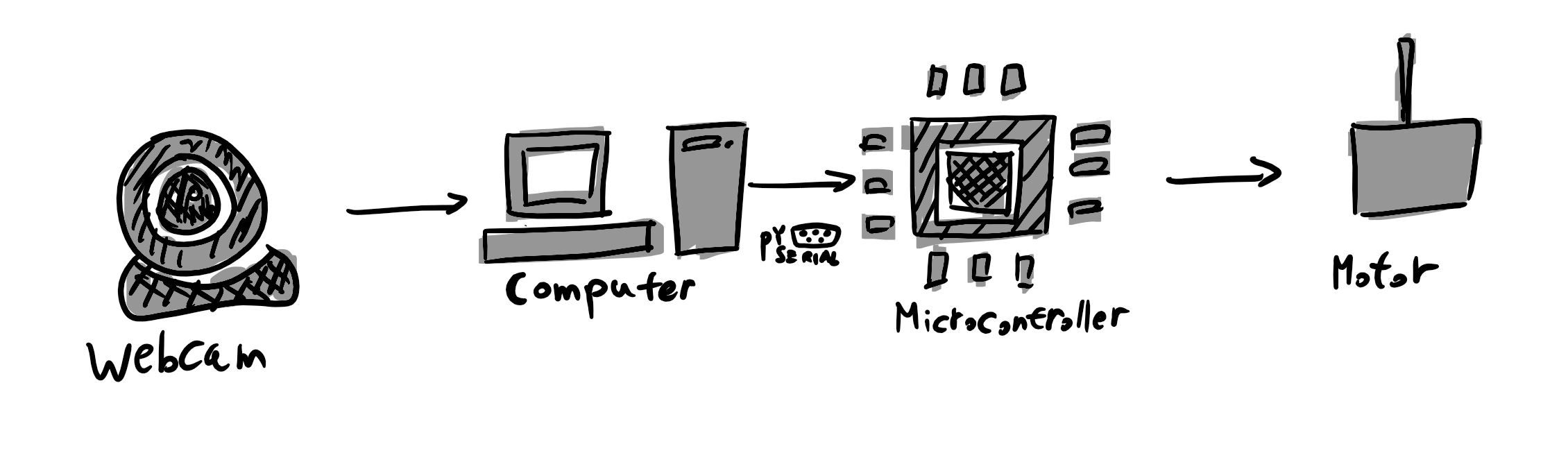
The platform is designed to have a two degrees of fredom driven by two stepper motors. Pan is the first motor that moves in vertical axis while the second motor is called tilt which rotates perpendicular to the first vertical axis, purely horizontal. AT Mega 328P -PU is choosen to performs the control of the motor using the arduino sketches. I contains a control program to drive the motors that get the input signals via a serial port. A 4988 is a microstepping motor driver with a simple operation. It operates bipolar stepper motors in full-, half-, quarter-, eighth- and sixteenth- step modes. In this system sixteeth step mode is choosen to get more accuracy than a holding torque. The system is equiped with a computer connected with USB to the camera and to the microcontroller.
2. 3D CAD Model
While designing the components I have always refer to the mechanical design of a robotic arm from different reference such as BCN3D robotic arm. I tried not to do everything from skretch but trying to develop the design and "Standing on the shoulders of giants". Moreover each part has each own purppose.

Fig 2.1 3D CAD

Fig 2.2 The base plate of the platform
2.1 Philosophy of design

Dieter Rams. Photograph by Abisag Tüllmann.
For the 3D design I am going to try the principle from Dieter Rams to get a good design. According to Dieter Rams, good design has this ten follwing priciples:
2.2 Old Design
The old design was totally full of addictive manufacturing. Addictive manufacturing takes so much time compare to substractive, therefore I tried to replace the manufacturing strategy.

Fig 2.1 : 3D CAD to see the planetary inner gear.

Fig 2.2 : Sketch of the pan and tilt of 3D CAD.
2.3 3D Download
Pan and tilt 3D CAD and 2D drawing
3. 2D design
3.1 2D drawing


From the 3D CAD file I projected them into 1:1 scale and save them as DXF file to be laser cut and CNC.
3.2 3D Download
Pan and tilt 3D CAD and 2D drawing
4. Electronic
4.1 Main board PCB

This PCB board for the robot is modified from satshakit-grbl. I modified the board to have plug and play connections and the shape is designed to fit to the base.

Engrave this image

Cut this PCB
4.2 Motor driver PCB

I have choosen the sixteenth microstepping to have a smoother resolution and accurate movement. Therefore pin MSI1, MS2 and MS3 have to be coneected in 5v on a4988 stepper motor driver board.

This board is for the connection of the steper motor driver to the main board and the wires brings more electrons than the normal siganl from the microcontroller to compesante tha, a thicker wires are needed.
4.3 Remote control

Download this png file and engrave it.

Save this image to cut the PCB.
4.3.1 NRF24L01
NRF24L01 is a radio module that I use to control an electric skateboard.
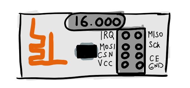
This module is powered by 3.3 Volts and this is why on the main board I have to add voltage regulator.
4.4 Electronics Assembly

Attach all the components in the case at the botton of the platform.

Attach the radio module and the voltage regulator.

4.5 Electronics Download
5. Architecture
5.1 Camera

Rolling Shutter versus Global Shutter.
Rolling shutter is a technical term where the image scans sequentially, from one side of the sensor to the other, line by line. In contrast, global shutter is referring to sensors that scan the entire area of the image simultaneously.
What happens when the rolling shutter is being use for a fast moving object? The image are going to be exaggerate and shift.Therfore a sensor type of global shutter is really needed.
Options for a camera:
6. Programming
Computer Vision
Definition : Computer Vision is a cutting edge field of computer science that aims to enable computers to understand what is being seen in an image+.
6.1 Challenges:
Installations
Python & OpenCV Windows installation
Step 1: Download and Install Anaconda Python Package
Go to :https://www.anaconda.com/download/
Select appropriate version - either Python 2.7 or 3.5
Test- Go to Anaconda and then launch Jupyter notebook
Step 2: Download and Run OpenCV
Go to https://opencv.org/releases.html
Select and download the appropriate version
Step 3: Open the download file and Extract it. Eg. Extract to disk C
The open CV file should be found here : C:\opencv\build\python\2.7\x64
After finding the CV2.py file, copy this file and paste it in the following directory: C:\Users\cllom\Anaconda3\Lib\site-packages
Or
Step 3 :Open Anaconda Prompt
Conda install opencv
Check if the library is installed correctly
Open Jupyter Notebooks
Create new file and run the following code: import cv2
Imutils
In anaconda command prompt
                          pip install imutils

                              conda install Pillow
6.2 Direct algorithm

In the previous algorithm I have programmed them moving like a joystick and I have found them too slow therefore I made the new algorithm so the target can be followed directly by measuring the errors.
import cv2
import numpy as np
from IPython.display import clear_output
import IPython

# comunication from Python to arduino
import serial, time
import struct

arduino = serial.Serial('COM6', 1000000, timeout=.1)
time.sleep(1)  # give the connection a second to settle
arduino.write(("Hello from Python!").encode())

# Set camera resolution.
cameraWidth = 640
cameraHeight = 480

face_classifier = cv2.CascadeClassifier('Haarcascades/haarcascade_frontalface_default.xml')

# calculate the middle screen
midScreenX = int(cameraWidth / 2)
midScreenY = int(cameraHeight / 2)

midScreenWindow = 1

def printArduino2Python(q1,q2):
    # sending string to arduino

    arduino.write(q1.encode())
    arduino.write('and'.encode())
    arduino.write(q2.encode())

    time.sleep(0.05)  # give the connection a second to settle

    # print the data from arduino to python


    data = ''
    data = arduino.readline()[:]  # the last bit gets rid of the new-line chars
    if data:
        data = str(data)
        data = data.replace("b", "").replace("\\r", "").replace("\\n", "").replace("'", "")
        print(data)  # Read the newest output from the Arduino

    data = ''
    data = arduino.readline()[:]  # the last bit gets rid of the new-line chars
    if data:
        data = str(data)
        data = data.replace("b", "").replace("\\r", "").replace("\\n", "").replace("'", "")
        print(data)  # Read the newest output from the Arduino

    print("-------------------------")


def face_detector(img):
    # Convert image to grayscale
    gray = cv2.cvtColor(img, cv2.COLOR_BGR2GRAY)

    # Clasify face from the gray image
    faces = face_classifier.detectMultiScale(gray, 1.3, 5)
    if faces is ():
        return img, []

    for (x, y, w, h) in faces:
        cv2.rectangle(img, (x, y), (x + w, y + h), (0, 255, 255), 2)
        # find the midpoint of the first face in the frame.
        xCentre = int(x + (w / 2))
        yCentre = int(y + (w / 2))
        cv2.circle(img, (xCentre, yCentre), 5, (0, 255, 255), -1)

        localization = [xCentre, yCentre]
        # print(localization)
    return img, localization

# Open Webcam
cap = cv2.VideoCapture(1)  # 0 is camera device number, 0 is for internal webcam and 1 will access the first connected usb webcam

# Set camera resolution. The max resolution is webcam dependent
# so change it to a resolution that is both supported by your camera
# and compatible with your monitor
cap.set(cv2.CAP_PROP_FRAME_WIDTH, cameraWidth)
cap.set(cv2.CAP_PROP_FRAME_HEIGHT, cameraHeight)

while True:

    # Capture frame-by-frame
    ret, frame = cap.read()

    # mirror the frame
    frame = cv2.flip(frame, 1)

    image, face = face_detector(frame)

    # cv2.line(image, starting cordinates, ending cordinates, color, thickness)
    # vertical line
    cv2.line(image, (midScreenX , 0), (midScreenX, cameraHeight), (255, 127, 0),2)

    # horizontal line
    cv2.line(image, (0, midScreenY), (cameraWidth, midScreenY), (255, 127, 0),2)

    # only if the face is recoginize
    if len(face) == 2:
        midFaceX = face[0]
        midFaceY = face[1]

        a=1800 #adjust this according to the distance of the person

        # calculating the distance errors x and y
        dx = midFaceX- midScreenX
        dy = midScreenY - midFaceY

        # finding the angle to fix the errors
        if((dy != 0) & (dx != 0)): # to prevent an invalid result when its division is zero
            #calculating the angle q1 and q2
            q1 = np.arctan(dx/a)
            q2 = np.arctan(dy/a)


            q1Str = str(q1)
            q1Str = q1Str[0:5] # Truncate the string to 5 characters.
            print("q1:", q1Str)
            print("q1deg:", np.degrees(q1))


            q2Str = str(q2)
            q2Str = q2Str[0:5] # Truncate the string to 5 characters.
            print("q2:", q2Str)
            print("q2deg:", np.degrees(q2))

            printArduino2Python(q1Str,q2Str)

            #Print value q1 and q2 on the image
            cv2.putText(image, "q1: " + str(np.degrees(q1)), (250, 400), cv2.FONT_HERSHEY_COMPLEX, 1, (0, 255, 0), 2)
            cv2.putText(image, "q2: " + str(np.degrees(q2)), (250, 450), cv2.FONT_HERSHEY_COMPLEX, 1, (0, 255, 0), 2)


        cv2.putText(image, "dx: " + str(dx), (0, 400), cv2.FONT_HERSHEY_COMPLEX, 1, (0, 255, 0), 2)
        cv2.putText(image, "dy: " + str(dy), (0, 450), cv2.FONT_HERSHEY_COMPLEX, 1, (0, 255, 0), 2)
            # print(x)
            # print(y)


    # Display the resulting frame
    cv2.imshow('Video', frame)

    # Press Q on keyboard to  exit
    if cv2.waitKey(25) & 0xFF == ord('q'):
        break

# When everything is done, release the capture
# video_capture.release()
app = IPython.Application.instance()
app.kernel.do_shutdown(True)  # turn off kernel
clear_output()  # clear output
cv2.destroyAllWindows()
6.2.1 Download Python
6.3 Joystick Algorithm

This is the pervious algorithm and it works like a joystick.
                            import cv2

                            import numpy as np

                            from IPython.display import clear_output

                            import IPython


                            # Set camera resolution.

                            cameraWidth = 640

                            cameraHeight = 480


                            face_classifier = cv2.CascadeClassifier('haarcascade_frontalface_default.xml')


                            # calculate the middle screen

                            midScreenX = int(cameraWidth / 2)

                            midScreenY = int(cameraHeight / 2)


                            midScreenWindow = 100


                            def face_detector(img):

                                # Convert image to grayscale

                                gray = cv2.cvtColor(img, cv2.COLOR_BGR2GRAY)


                                # Clasify face from the gray image

                                faces = face_classifier.detectMultiScale(gray, 1.3, 5)

                                if faces is ():

                                    return img, []


                                for (x, y, w, h) in faces:

                                    cv2.rectangle(img, (x, y), (x + w, y + h), (0, 255, 255), 2)

                                    # find the midpoint of the first face in the frame.

                                    xCentre = int(x + (w / 2))

                                    yCentre = int(y + (w / 2))

                                    cv2.circle(img, (xCentre, yCentre), 5, (0, 255, 255), -1)


                                    localization = [xCentre, yCentre]

                                    # print(localization)

                                return img, localization


                            # Open Webcam

                            cap = cv2.VideoCapture(0)  # 0 is camera device number, 0 is for internal webcam and 1 will access the first connected usb webcam


                            # Set camera resolution. The max resolution is webcam dependent

                            # so change it to a resolution that is both supported by your camera

                            # and compatible with your monitor

                            cap.set(cv2.CAP_PROP_FRAME_WIDTH, cameraWidth)

                            cap.set(cv2.CAP_PROP_FRAME_HEIGHT, cameraHeight)


                            while True:


                                # Capture frame-by-frame

                                ret, frame = cap.read()


                                # mirror the frame

                                frame = cv2.flip(frame, 1)


                                image, face = face_detector(frame)


                                # cv2.line(image, starting cordinates, ending cordinates, color, thickness)

                                # left vertical line

                                cv2.line(image, ((midScreenX - midScreenWindow), 0), ((midScreenX - midScreenWindow), cameraHeight), (255, 127, 0),2)

                                # right vertical line

                                cv2.line(image, ((midScreenX + midScreenWindow), 0), ((midScreenX + midScreenWindow), cameraHeight), (255, 127, 0),2)

                                # up horizontal line

                                cv2.line(image, (0, (midScreenY - midScreenWindow)), (cameraWidth, (midScreenY - midScreenWindow)), (255, 127, 0),2)

                                # down horizontal line

                                cv2.line(image, (0, (midScreenY + midScreenWindow)), (cameraWidth, (midScreenY + midScreenWindow)), (255, 127, 0),2)


                                # only if the face is recoginize

                                if len(face) == 2:

                                    midFaceX = face[0]

                                    midFaceY = face[1]

                                    # Find out if the X component of the face is to the left of the middle of the screen.

                                    if (midFaceX < (midScreenX - midScreenWindow)):

                                        cv2.putText(image, "Move Left", (250, 450), cv2.FONT_HERSHEY_COMPLEX, 1, (0, 255, 0), 2)

                                        # if(servoPanPosition >= 5):

                                        # servoPanPosition -= stepSize; #Update the pan position variable to move the servo to the left.

                                    if (midFaceX > (midScreenX + midScreenWindow)):

                                        cv2.putText(image, "Move Right", (250, 450), cv2.FONT_HERSHEY_COMPLEX, 1, (0, 255, 0), 2)

                                    if (midFaceY < (midScreenY - midScreenWindow)):

                                        cv2.putText(image, "Move Up", (250, 450), cv2.FONT_HERSHEY_COMPLEX, 1, (0, 255, 0), 2)

                                    if (midFaceY > (midScreenY + midScreenWindow)):

                                        cv2.putText(image, "Move Down", (250, 450), cv2.FONT_HERSHEY_COMPLEX, 1, (0, 255, 0), 2)


                                        # print(x)

                                        # print(y)


                                # Display the resulting frame

                                cv2.imshow('Video', frame)


                                # Press Q on keyboard to  exit

                                if cv2.waitKey(25) & 0xFF == ord('q'):

                                    break


                            # When everything is done, release the capture

                            # video_capture.release()

                            app = IPython.Application.instance()

                            app.kernel.do_shutdown(True)  # turn off kernel

                            clear_output()  # clear output

                            cv2.destroyAllWindows()
First of all, I am using a face detection library from OpenCV. The webcam will reads it frame by frame and it converts the image into grayscale. The result of library is an array of rectangle which represents the coordiates of a detected rectangle arround each of the faces. The coordinate that is given by the library is the top left corner relative to the frame, therfore I calculate the centre point of the square.
The idea is to keep a face in the centre of the picture, therefore I devided the picture into 9 boxes and sending where the direction of the motor should move to the microcontroller.Then simply print the direction where the pan and tilt should rotate.
6.3.1 Video
Result:
6.4 Pyserial
Python:
                                    import serial, time

                                    ser = serial.Serial('COM22', 115200, timeout=.1)

                                    time.sleep(1) #give the connection a second to settle

                                    ser.write(("Hello from Python!").encode())


                                    while True:

                                          var = input("Enter something: ")

                                          ser.write(var.encode())

                                          print(var.encode())

                                          try:

                                                print(ser.readline())

                                                time.sleep(1)

                                          except ser.SerialTimeoutException:

                                                print('Data could not be read')

                                          time.sleep(1)
Microcontroller:
Python:
6.5 Input and Output
This is a program to control a stepper motor with a joystick.
Simulation
Install visual python on Anaconda using pip or conda
http://www.glowscript.org/#/user/GlowScriptDemos/folder/Examples/
                                  conda install -c vpython vpython
                                  pip install vpython
6.6 Remote control
/*
*
* Library: TMRh20/RF24, https://github.com/tmrh20/RF24/
*/
#include
#include
#include
RF24 radio(7, 8); // CE, CSN
const byte address[6] = "00001";


// input pins
const byte x      = A0;   // X input connected to A0
const byte y      = A1;   // Y input connected to A1
const byte button = 4;    // pushbuttom input connected to Digital pin 4


// state machine
int stateButton       = 0; // starting with state 0: waiting for button to be pressed
unsigned long startTime; // will be set in state 1
unsigned long stopTime; // will be set in state 1

unsigned long now = millis(); // current (relative) time in msecs.

int debounceTicks = 300;      // number of millisec that have to pass by before a click is assumed as safe.
int clickTicks = 500;        // number of millisec that have to pass by before a click is detected.
int pressTicks = 2000;       // number of millisec that have to pass by before a long button press is detected.

//threshold because of physical limitation 533 centre of joystick at x axis
const int THRESHOLD_LOW_X   = 200;
const int THRESHOLD_HIGH_X  = 900;

//threshold because of physical limitation 522 centre of joystick at y axis
const int THRESHOLD_LOW_Y   = 200;
const int THRESHOLD_HIGH_Y  = 900;

// joystick value
int sensorValuex,sensorValuey, buttonState;

boolean flagClick ;

//led
const int led =4;

void setup() {
  // put your setup code here, to run once:
  Serial.begin(1000000);               // initialize serial communication

  //Input
  pinMode (button, INPUT_PULLUP); // internal pull up resistor
  pinMode (x, INPUT);             // initialize Xin as INPUT
  pinMode (y, INPUT);             // initialize YZin as INPUT

  pinMode (led, OUTPUT);             // pin 4 led as output

  digitalWrite(LED_BUILTIN, HIGH);   // turn the LED on (HIGH is the voltage level)

  //radio setup NRF24L01
  radio.begin();
  radio.openWritingPipe(address);
  radio.setPALevel(RF24_PA_MIN);
  radio.stopListening();
}
void loop() {

  buttonState = digitalRead(button);  // read input value
  //Serial.print("buttonState: ");
  //Serial.println(buttonState);
  now= millis(); // update variable now
      //Starting (State 0)
    if (stateButton == 0) { // waiting for One pin being pressed.
      if ( buttonState == false) { //if button is pressed

         stateButton = 1; // step to state 1
         startTime = now; // remember starting time
         flagClick = true;
      }

    }else if(stateButton == 1) { // waiting for One pin being released.
       //Serial.println("state 1!");
       //Serial.print("Start time:");
       //Serial.println(startTime);
       //Serial.print("now:");
       //Serial.println(now);
      if(buttonState == true) { // if button is not pressed
          delay(debounceTicks);
          stateButton = 2;
          stopTime = now; // remember stopping time
       }else if((buttonState == true) &&  ((unsigned long)(now - startTime) < debounceTicks)){
          Serial.println("State1 Debouncing");
        // button was released to fast means that this is debouncing
          stateButton =0;
       }else{
        //wait. Stay in this state
       }


    }else if(stateButton ==2){
        if (now > startTime + clickTicks ) {
        // this was only a single short click
       // Serial.println("state 2!");

        click(); //toggle LED yes LED


       }else if ((buttonState == false)&& ((unsigned long)(now - stopTime) > debounceTicks) ){
          startTime = now; // remember starting time
          stateButton =3;


       }
    }else if(stateButton ==3){
      if(  buttonState == true){// button release and this is double click

        doubleClick();
       // Serial.println("state 3!");
        //Serial.println("Double Click!");
         startTime = now; // remember starting time
         delay(debounceTicks); //debouncing delay
        stateButton = 0; // restart.

      }else if((buttonState == true) && ((unsigned long)(now - startTime) < debounceTicks)){
        // button was released to fast means that this is debouncing
          stateButton =0;
       }


    }
}

int statePanTilt;

void readPotentiometer(){
  sensorValuex  = analogRead(x);
  sensorValuey  = analogRead(y);

}

int stateJoystick;

void moveAxis(){

 if(stateJoystick == 0){
  readPotentiometer();
  if(sensorValuex > THRESHOLD_HIGH_X){ //move right
   stateJoystick = 1;
  }else if(sensorValuex < THRESHOLD_LOW_X){ //move left
   stateJoystick = 2;
  }else if(sensorValuey > THRESHOLD_HIGH_Y){ //move down
   stateJoystick = 3;
  }else if(sensorValuey < THRESHOLD_LOW_Y){ //move up
   stateJoystick = 4;
  }if ( buttonState == false) { //if button is pressed
       stateButton = 3; // step to state 3 to change the mode
   }
 }else if(stateJoystick ==1){
  statePanTilt=3;
  radio.write(&statePanTilt, sizeof(statePanTilt));
  Serial.print("statePanTilt");
  Serial.println(statePanTilt);
  readPotentiometer();
  if((sensorValuex < THRESHOLD_HIGH_X)  && (sensorValuex > THRESHOLD_LOW_X)){
   restartJoytstick();


 }

 }else if(stateJoystick ==2){
  statePanTilt=4;
  radio.write(&statePanTilt, sizeof(statePanTilt));
  Serial.print("statePanTilt");
  Serial.println(statePanTilt);
  readPotentiometer();
  if((sensorValuex < THRESHOLD_HIGH_X)  && (sensorValuex > THRESHOLD_LOW_X)){
   restartJoytstick();
  }

 }else if(stateJoystick ==3){
  statePanTilt=5;
  radio.write(&statePanTilt, sizeof(statePanTilt));
  Serial.print("statePanTilt");
  Serial.println(statePanTilt);
  readPotentiometer();
  if((sensorValuey < THRESHOLD_HIGH_Y)  && (sensorValuey > THRESHOLD_LOW_Y)){
   restartJoytstick();
  }

 }else if(stateJoystick ==4){
  statePanTilt=6;
  radio.write(&statePanTilt, sizeof(statePanTilt));
  Serial.print("statePanTilt");
  Serial.println(statePanTilt);
  readPotentiometer();
    if((sensorValuey < THRESHOLD_HIGH_Y)  && (sensorValuey > THRESHOLD_LOW_Y)){

       restartJoytstick();
    }

  }

}

void restartJoytstick(){
  stateJoystick = 0; // joy stick at the centre back to state 0


}


void click(void){
  statePanTilt=1;


  if (flagClick== true){
    radio.write(&statePanTilt, sizeof(statePanTilt));
    flagClick =false;
    Serial.println("Click!");
    digitalWrite(LED_BUILTIN, HIGH);   // turn the LED on (HIGH is the voltage level)
  }


  moveAxis();

}

void doubleClick(void){
  digitalWrite(LED_BUILTIN, LOW);   // turn the LED on (HIGH is the voltage level)
  statePanTilt=2;
  radio.write(&statePanTilt, sizeof(statePanTilt));
  Serial.println("Double Click!");
}
Download
6.7 Main board Program
/*
  Marcello Tania
*/
#include
#include
#include
RF24 radio(7, 8); // CE, CSN
const byte address[6] = "00001";

// Output pin

float tiltRad =0 ;
float panRad =0 ;

const int dirPin1 = 5;
const int stepPin1 = 4;

const int dirPin2 = 3;
const int stepPin2 = 2;

const int dirPin3 = 9;
const int stepPin3 = 10;


int led = 6;   // pin 6 for the LED

float delaySpeed ;
int maxDelaySpeed =500;
int minDelaySpeed =100;


int state=2;// initiliaze automous mode at the beginning

// the setup function runs once when you press reset or power the board
void setup() {

  // initialize serial communication
  Serial.begin(1000000); // use the same baud-rate as the python side
  while (!Serial);

  //Setup the nRF24L01 radio module
  radio.begin();
  radio.openReadingPipe(0, address);
  radio.setPALevel(RF24_PA_MIN);
  radio.startListening();


  // initialize digital pins as an output.
  pinMode(stepPin1,OUTPUT);
  pinMode(stepPin2,OUTPUT);
  pinMode(stepPin3,OUTPUT);
  pinMode(dirPin1,OUTPUT);
  pinMode(dirPin2,OUTPUT);
  pinMode(dirPin3,OUTPUT);

  pinMode(led,OUTPUT);


}


// the loop function runs over and over again forever
void loop() {

  if (radio.available()) {

    radio.read(&state, sizeof(state));
    // Serial.print("state:");
    //Serial.println(state);
    switch(state){
      case 1:
        digitalWrite(led, HIGH);  // turn LED ON
       // Serial.println("manual");
        break;
      case 2:
        digitalWrite(led, LOW);  // turn LED ON
        autonomousMode();
       // Serial.println("autonomous");
        break;
      case 3://error
        movement(0,1, 1200);
       // Serial.println("up");
        break;
      case 4:
        movement(0,-1, 1200);
       // Serial.println("down");
        break;
      case 5:
      movement(1,0, 700);
       // Serial.println("right");
        break;

      case 6:
       // Serial.println("left");
        movement(-1,0, 700);
        break;

    }

  }else if (state==2){  //if the radio is not available go to autonomous mode
    autonomousMode();
  }


}

void autonomousMode(){


  if (Serial.available()) {
    panRad = Serial.parseFloat();// first value of the serial
    tiltRad = Serial.parseFloat();// second value of the serial


    movement(rad2deg(panRad),rad2deg(tiltRad));


  }
}

float rad2deg(float rad){
  //this function convert radian to degrees
  float degree = rad*57.2958; //convert rad to degrees
  return degree;
}


void movement(float panDegree, float tiltDegree){


  //calculating the steps for pan and tilt
  int panSteps = panDegree/0.0375;
  int tiltSteps = tiltDegree/0.0375;


  //geting the right direction for pan
  if(panDegree <0){
    digitalWrite(dirPin3,LOW); // Enables the motor  to move in a particular direction
    panSteps = abs(panSteps); // make the stepping as a + value
    Serial.println("right");
  }else if(panDegree>0){
    digitalWrite(dirPin3,HIGH); // Enables the motor  to move in a particular direction
    Serial.println("left");
  }

  //geting the right direction for tilt

  if(tiltDegree<0){
     digitalWrite(dirPin1,HIGH); // Enables the motor  to move in a particular direction
     digitalWrite(dirPin2,LOW); // Enables the motor  to move in a particular direction
     tiltSteps = abs(tiltSteps); // make the stepping as a + value
     Serial.println("moveDown");
  }else if(tiltDegree>0){
     digitalWrite(dirPin1,LOW); // Enables the motor  to move in a particular direction
     digitalWrite(dirPin2,HIGH); // Enables the motor  to move in a particular direction
     Serial.println("moveUp");
  }


  //geting the maximum value between the panSteps and tiltSteps
  int maximumSteps = max(panSteps,tiltSteps);

  boolean panMaximum;
  int steps;
  int ratioPanTiltSteps;
  if(maximumSteps == panSteps){
    panMaximum = true;
    //Serial.println("panSteps is the maximum");
    steps = panSteps;
    if(tiltSteps |=0){
    ratioPanTiltSteps= abs(panSteps/tiltSteps); // calculating the integer of the ratio because pan is bigger than tilt
    }else{
      ratioPanTiltSteps = panSteps;
    }
  }else if(maximumSteps == tiltSteps){
    panMaximum = false;
    steps = tiltSteps;
    //Serial.println("panSteps is the minimum");
    if(panSteps|=0){
      ratioPanTiltSteps= abs(tiltSteps/panSteps); // calculating the integer of the ratio because tilt is bigger than pan
    }else{
      ratioPanTiltSteps= tiltSteps;
    }

  }


//variable for acceleration and decelerate
  float fourthSteps = steps/4;
  float threeFourthsSteps =3/4*steps;
  delaySpeed = maxDelaySpeed;
  float deltaDelaySteps =float(maxDelaySpeed-minDelaySpeed)/fourthSteps;


  int subCounter = 0; // counter to wait and syncronize the slower movement of pan or tilt

   for(int x = 0; x < steps; x++) {
      //Serial.print("x :");
      //Serial.println(x);
      if(xthreeFourthsSteps){
      //accelerate half of the sum of the steps
        delaySpeed +=  deltaDelaySteps ;

      }

      if ( panMaximum == true){

        digitalWrite(stepPin3,HIGH);
        delayMicroseconds(delaySpeed);
        digitalWrite(stepPin3,LOW);
        delayMicroseconds(delaySpeed);
        if( subCounter == ratioPanTiltSteps){
          subCounter =0;
          digitalWrite(stepPin1,HIGH);
          digitalWrite(stepPin2,HIGH);
          delayMicroseconds(delaySpeed);
          digitalWrite(stepPin1,LOW);
          digitalWrite(stepPin2,LOW);
        }
        subCounter++;
      }else if (panMaximum == false){
        digitalWrite(stepPin1,HIGH);
        digitalWrite(stepPin2,HIGH);
        delayMicroseconds(delaySpeed);
        digitalWrite(stepPin1,LOW);
        digitalWrite(stepPin2,LOW);
        if( subCounter == ratioPanTiltSteps){
          subCounter =0;
          digitalWrite(stepPin3,HIGH);
          delayMicroseconds(delaySpeed);
          digitalWrite(stepPin3,LOW);
          delayMicroseconds(delaySpeed);
        }
        subCounter++;
      }
   }


}


void movement(float panDegree, float tiltDegree, float delaySpeed){

  //calculating the steps for pan and tilt
  int panSteps = panDegree/0.0375;
  int tiltSteps = tiltDegree/0.0375;


  //geting the right direction for pan
  if(panDegree <0){
    digitalWrite(dirPin3,LOW); // Enables the motor  to move in a particular direction
    panSteps = abs(panSteps); // make the stepping as a + value
    Serial.println("right");
  }else if(panDegree>0){
    digitalWrite(dirPin3,HIGH); // Enables the motor  to move in a particular direction
    Serial.println("left");
  }

  //geting the right direction for tilt

  if(tiltDegree<0){
     digitalWrite(dirPin1,HIGH); // Enables the motor  to move in a particular direction
     digitalWrite(dirPin2,LOW); // Enables the motor  to move in a particular direction
     tiltSteps = abs(tiltSteps); // make the stepping as a + value

  }else if(tiltDegree>0){
     digitalWrite(dirPin1,LOW); // Enables the motor  to move in a particular direction
     digitalWrite(dirPin2,HIGH); // Enables the motor  to move in a particular direction

  }


  //geting the maximum value between the panSteps and tiltSteps
  int maximumSteps = max(panSteps,tiltSteps);

  boolean panMaximum;
  int steps;
  int ratioPanTiltSteps;
  if(maximumSteps == panSteps){
    panMaximum = true;
    //Serial.println("panSteps is the maximum");
    steps = panSteps;

      ratioPanTiltSteps = panSteps;

  }else if(maximumSteps == tiltSteps){
    panMaximum = false;
    steps = tiltSteps;
    //Serial.println("panSteps is the minimum");

      ratioPanTiltSteps= tiltSteps;


  }


  int subCounter = 0; // counter to wait and syncronize the slower movement of pan or tilt
 for(int x = 0; x < steps; x++) {

      if ( panMaximum == true){

        digitalWrite(stepPin3,HIGH);
        delayMicroseconds(delaySpeed);
        digitalWrite(stepPin3,LOW);
        delayMicroseconds(delaySpeed);

      }else if (panMaximum == false){
        digitalWrite(stepPin1,HIGH);
        digitalWrite(stepPin2,HIGH);
        delayMicroseconds(delaySpeed);
        digitalWrite(stepPin1,LOW);
        digitalWrite(stepPin2,LOW);

      }

 }
}
Download
7. CNC

In action!

7.1 Preparation
First of all save the 2d drawing into a dxf file and make them into different layers to cut them in order and mill it with different tool. I made them having different colours so it is easier to differentiate each of the layers.

7.2 drill 3mm holes
Setting

On the program menu, choose Ofset and cut through till the final z is -0.15 to make sure that the material is cut and we sacrified the bed a litle bit. Make sure that the method is Inside Counter clockwise so it will have exactly 3 mm holes and I have drawn to it 3.2 mm to have little bit of lose and it wont tide fit.
Engrave
The engrave are for the inserting the bearings, champfer and the stepper motors.
Setting

The material has a thickness of 18 mm and we want to engrave 5 mm deep so 18 mm minus 5 mm is equal to 13 mm. Therefore, the final z is 13. Set them with "Pocket setting".
Stepper Motors
Setting

This is the result that you are going to expect for the engraving.

7.3 Drill holes with 6mm drill

Basically the setting is the simili;ar with the 3 mm drill except the tool number, tool diameter, the feed rate, plunge rate and spindle speed because the tool has different properties thatn the 3 mm drill. It is stronger than the 6 mm so we can mill it faster and remove more material.
7.4 Cut outer
Setting

Last but not least, after cutting all the inside part it is time to cut the outer parts. It is the last to make sure that the workpiece is not moving while cutting the other holes or engrave the inside parts. The setting has to be Outside CW to make sure that we are have the exactly dimension and cut outside the lines.
7.5 Result CNC

8. Parts
8.1 Belt tensioner assembly

Insert the 3 mm screw into the this hole and make sure that the champfer is fit to the screw.

Insert the belt tensioner on the other side.

8.2 Champfer on the other side
The CNC engrave only on side and it is very difficult to set exacltly the home posisition again so I decided to drill the champfer on the other side manually.

The champfer diameter is 6 mm according to the diamter of the screw and the depth is 5mm.

Then assembly the stepper motors.

8.3 Assembly head

You will need a rubber head hammer and all the head parts.

Taraa!!
8.4 Belt tensioner adjuster

This part is to insert a screw to adjust the belt tensioner into the head part.

8.5 Cut the 8 mm rod

Cut the rod with a dremel with a cutting wheel.
8.6 Laser Cut
Laser cut this POM
It is a strong material compare to a plywood so I have choosen this to fasten this from the rod to the camera.
Laser cut the acrylic
I have choosen acrylic beacause it is transparent so I could easily install the camera and taking a look where the hole screw is.
8.7 tilt

After laser cut the pom cut the hole a the centre to have a screw inserting.

Insert the "Brass Threaded Insert" by heating up with a solder and insert them into the holes and let the outer melt.

The M3 brass threaded has succesfully inserted.

At the end you could insert the m3 screw to fasten this to the rod securely.

Pan Screw

The parts are laser cut POM, M8 screw and m5 screws.

9. 3D printing


The material I used is ABS and to be able to print an ABS you have to take care to control the room temperature and I have to install this enclosure adjust speed and the builplate temperature.
10. Foward kinematic and inverse kinematic

'''
pan and tilt simulation
marcello tania
Forward Kinematics of a pan and tilt
'''


import matplotlib.pyplot as plt
from mpl_toolkits.mplot3d import Axes3D
from matplotlib.animation import FuncAnimation
#https://matplotlib.org/mpl_toolkits/mplot3d/tutorial.html
import numpy as np

# definition of the fixed robot parameters
h = 1
l1 = 1

def transformation_matrix(theta, d, a, alpha):

    A = np.matrix([[np.cos(theta), -np.sin(theta)*np.cos(alpha), np.sin(theta)*np.sin(alpha), a*np.cos(theta)],
                   [np.sin(theta), np.cos(theta)*np.cos(alpha), -np.cos(theta)*np.sin(alpha), a*np.sin(theta)],
                   [0, np.sin(alpha), np.cos(alpha), d],
                   [0, 0, 0, 1]])

    return A

def manipulator(q1,q2):


    #Denavit-Hartenberg-parameter
    # theta, d, a, alpha

    DH = np.matrix([[(np.pi/2)+q1, h, 0, np.pi/2],
                     [q2, 0, l1, 0]])


    #homogenous transformation matrices

    A1 = transformation_matrix(DH[0,0], DH[0,1], DH[0,2], DH[0,3])
    A2 = transformation_matrix(DH[1, 0], DH[1, 1], DH[1, 2], DH[1, 3])


    #forward kinematics

    T01 = A1
    H = A1*A2

    #representation of the joint coordinates in the inertial coordinate system
    #representation as local homogenous coordinates

    r_0_G1_hom = np.matrix([[0], [0], [0], [1]]) # vector of lever 1 described in homogenous coordinates within coordinate system 0

    r_1_G2_hom = np.matrix([[0], [0], [0], [1]]) # vector to joint 2 described in homogenous coordinates within coordinate system 1

    r_2_TCP_hom = np.matrix([[0], [0], [0], [1]])  # vector to TCP described in homogenous coordinates within coordinate system 2


    # representation as global homogenous coordinates

    r_0_G1_hom = r_0_G1_hom  # vector to joint 1 described in homogenous coordinates within coordinate system 0

    r_0_G2_hom = T01 * r_1_G2_hom # vector to joint 2 described in homogenous coordinates within coordinate system 0

    r_0_TCP_hom = H * r_2_TCP_hom  # vector to TCP described in homogenous coordinates within coordinate system 0


    #transformation of the homogenous coordinates into cartesian coordinates

    r_0_G1 = r_0_G1_hom[0:3]
    r_0_G2 = r_0_G2_hom[0:3]
    r_0_TCP = r_0_TCP_hom[0:3]

    ########################################################################################
    #visualitation

    fig = plt.figure()
    ax = fig.add_subplot(111, projection='3d')

    ax.set_xlabel('x axis')
    ax.set_ylabel('y axis')
    ax.set_zlabel('z Label')

    ax.set_xlim3d(-3, 3)
    ax.set_ylim3d(-3, 3)
    ax.set_zlim3d(0, 3)


    #joint positions
    ax.scatter(xs=[r_0_G1[0]], ys=[r_0_G1[1]], zs=[r_0_G1[2]], s=50, zdir='z', c='red', marker='o', depthshade=True)
    ax.scatter(xs=[r_0_G2[0]], ys=[r_0_G2[1]], zs=[r_0_G2[2]], s=50, zdir='z', c='purple', marker='o', depthshade=True)
    ax.scatter(xs= [r_0_TCP[0]], ys= [r_0_TCP[1]], zs= [r_0_TCP[2]], s=50, zdir='z', c='black', marker='o', depthshade=True)

    #representation of the levers
    ax.plot([0, r_0_G1[0]] , [0, r_0_G1[1]], zs=[0, r_0_G1[2]])
    ax.plot([float(r_0_G1[0]), r_0_G2[0]], [float(r_0_G1[1]), r_0_G2[1]], zs=[float(r_0_G1[2]), r_0_G2[2]])
    ax.plot([float(r_0_G2[0]), r_0_TCP[0]], [float(r_0_G2[1]), r_0_TCP[1]], zs=[float(r_0_G2[2]), r_0_TCP[2]])

    print( r_0_TCP)

    plt.show()
    #visualization of the end effector


def moving_manipulator():
    """
    this function gets called by FuncAnimation ecth time called
    """
    t=12
    manipulator(np.pi/2, np.pi/3)

    #manipulator(np.pi/6, np.pi/6)


'''
    for i in range (0, 1, t):
        phi1 = i/6
        phi2 = i/10
        manipulator(phi1,phi2)

'''
def inverseKinematics(xTCP, yTCP, zTCP):
    """
    TCP - Tool Centre Point
    q1 and q2 are the angle required for the motor to move to the coordinates of TCP.
    :param xTCP, yTCP and zTCP:
    :return q1 and q2:
    """

    if yTCP == 0:

        #there might be two solutions depends on the TCP coordinates
        q1= np.pi/2
    elif xTCP == 0:
        q1=0
    else:
        q1 = np.arctan2(xTCP/yTCP)

    if yTCP == 2:
        q2 = np.pi/2

    elif xTCP == 0:
        q2= 0

    else:
        q2 = np.arctan2((zTCP - h) / xTCP)
    print('q1', q1)
    print('q2', q2)
    return q1,q2
11. Project Development


what is the deadline? How much time do I have left?
Dealine is where you have to meet a certain goal. I added the networking because I still have time to upgrade my system.
what tasks have been completed, and what tasks remain?
All core task had been completed and the remaining task is how to make it more presentable.
how will I complete the remaining tasks in time?
Just do it! have a goal every day and complete them.
what has worked?
Everything has worked and I still want to optimize it.
what hasn't?
Everything has worked properly, I am just wondering if I could use better material.
what questions still need to be resolved?
I need to think for having anoher questions.
what have you learned?
So far I have learnt how to use all the machines in the fablab, designing an eletronic parts and develop my programming skill. Not only that, I also learned how to manage my time well and always be joyful! I had so much fun in this course"
12 Result
12.1 Media
12.1.1 Pan and tilt


12.1.2 Remote


12.1.3 Details


12.2 Combination

12. References
13. Downloads
© 2018 Marcello Tania . All rights reserved | marcello.tania@hsrw.org
