
My final project:
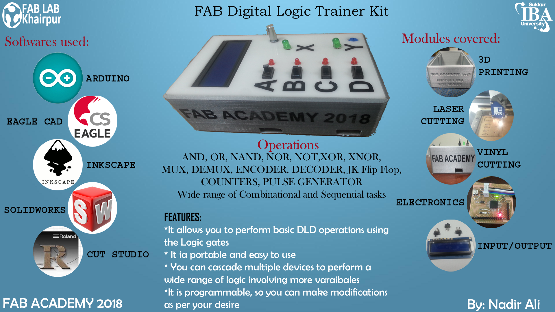
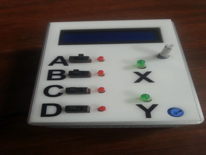
My final project is a device for performing different basic tasks of digital logic design. It is like a trainer module which are available in our electrical and electronics labs for different subjects.
In this project I have applied the knowledge which I learned in weekly assignments during my Fab academy. Below is the short description of the weekly tasks which helped me to build my final project.
- Project Management, to plan and document the progress of the project.
- Computer Aided Design, to choose best software for designing the 3D model for 3D printing, Laser cutting, and Vinyl cutting. I choose SolidWorks CAD software throughout my final project.
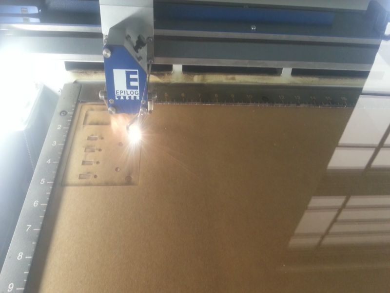
- Computer Controlled Cutting, to cut the acrylic sheet on Laser cutter machine, and sticker cutting in vinyl cutter machine for labeling the texts on the 3D box, and on the acrylic sheet of the project. I laser cut the acrylic sheet of 3mm thickness, and vinyl cut the stickers for labeling.
- Electronics Production, this helped me to make and mill the PCBs. I designed my PCBs in Eagle CAD software.
- Electronics Design, this helped me to choose right software for designing the PCBs, milling and soldering the PCBs and make my own microcontroller board. I designed atmega32U4 board, and I/O board.
- Embedded Programming, to investigate the right programming language in my microcontroller. I programmed my designed Atmega32U4 board, and connect the I/O board to it via jumper wires.
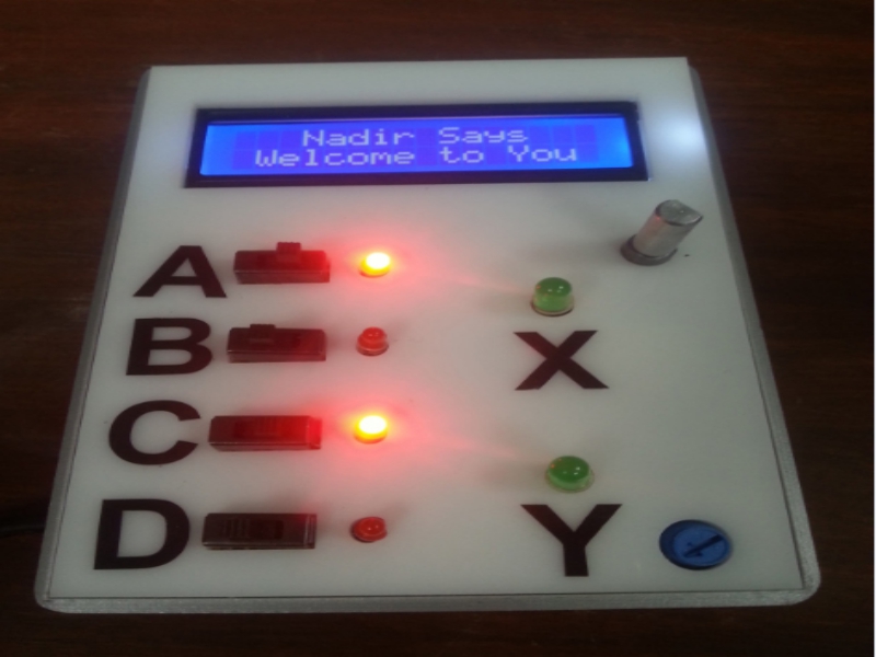
- Input Devices, to use buttons for changing the logic High to Low and vice versa. Sliding switches and rotary encoder are input devices in this project.
- Output Devices, to use LCD for displaying the tasks and selecting anyone of them. LCD and LEDs(SMDs, 3mm, and 5mm) are output devices in this project.
- Applications and Implications, to briefing about my project, what I have leaned during the process of final project.
- Invention, Intellectual property, and Income, to document for license of my projects and tasks.
Motivation behind this project
Nowadays in Pakistan, engineering Institutes and universities are increasing day by day to meet the increasing demand of technical skills of new generation of Pakistan. So every university and institute wants to develop well-equipped laboratories with reliable and efficient trainer kits and experimental devices. In Pakistan there is lack of producing reliable educational trainer modules, for this they are completely dependent on other countries and they import such modules and machines from other countries which includes heavy duty charges. In this way costly educational trainers are being purchased by universities. To overcome this problem I came up with an idea, why not we should design and develop such trainer modules so that academic institutes will no more be dependent on different conventional kits ordered from other countries, and can have access of these trainer kits and modules at their door steps easily in low price.
Way to be an Entrepreneur
In my opinion engineers must be inclined towards being an entrepreneur. Being a good entrepreneur needs a soft and technically sound mind, which is most of the engineers have :P . By availing the opportunities of different machines available in FabLab, we can design and many valuable products which could be commercialized easily. So, by tapping this need I came up with this idea of designing trainer kits for the educational institutes of our country. This digital device is my first intrusion towards my goal of being an entrepreneur.
Business Plan of my product
Mission StatementMy Mission is to be the prominent distributing channel of Digital Logic Design Trainer Kit to the universities of Pakistan. I want to design and develop DLD trainer module which is very unique and efficient design of trainer kit and can be easily available in Pakistan. I want our economy to be stronger. It’s our aim to make our nation independent in terms of technology by designing and providing the highly cost effective trainer kits to the universities of Pakistan.
Goals and Plan- To be the first home made electronic distribution channel in Pakistan.
- Enhance the development of trainer kit through updated technology every year.
- To provide low cost, most reliable trainer kits to academic institutes so that they will no more be dependent on different conventional kits imported from other countries.
- To equip our laboratories with locally made advanced machines and trainer kits.
- To mitigate the technological deficiency of Pakistan by products designed and made in our FabLab.
- To change the conventional method of learning and teaching to interactive learning and teaching by using our designed products in our universities.
- To increase the employment opportunities for the engineers and will strengthen the economy of Pakistan.
Strength
- Very Low Price compared to Foreign Competitors.
- Service of maintenance.
- First Mover.
- No direct Competitor at national level.
- Designed under the provision of FAB LAB
- Still dependent on foreign countries for fabrication (for initial years)
- Potential Competitor could try to copy our product.
- Coordination problem between personals.
- No other Industry provides home made Lab equipments and trainer kits in our country.
- Less Marketing Expense.
- Highly Profitable.
- Standardized equipments in labs are highly needed in Colleges, Institutes and Universities of our country.
- Threat of new entrants.
- Risk of failure.
- Risk of substitute.
- Threat of other competitors.
Marketing Mix 4P's
Product- Digital Logic Trainer kits with three different versions.
- Trainer kits for many other subjects like:
- Linear and Network Circuit Analysis (LCA & NCA)
- Basic Electronic kits
- Instrumentation and Measurement kits
- Control System
- Power Electronics
- Electronics kits for intermediate/A-Level students
- Snap Circuits for kids
In all these kits, there will be some unique points which will differentiate our designed modules from other existing ones. Our All products have minimum two different versions one is for moderate level and another one is for advanced level. Advanced level products will be designed for graduation and Masters level.
Price
I will be using penetrating pricing strategy. As I have claimed that I will providing this trainer kit with minimal cost compared to its imported counterpart. For making this trainer kit the expected cost is USD $20 per unit and we will be initiating with the price of USD $50 per unit. This amount is very much low if we compare to other such devices which are imported from different countries.
Place
I will be having my own warehouse at Sukkur, Sindh Pakistan.
Promotion
For promotion of Trainer kit I will follow the following strategies:
- Emails to Educational Institutes.
- Contact through my own website.
- Direct contact to Registrars of Educational Institutes.
- Face to face meet ups with customers.
My sincere thanks are with my friends of Business department of our University Sukkur IBA University, who helped me by understanding the business plan of my final project. I am happy to mention their names here: Iqra Akram, Sahar Kanwal, Faiza Arain, and Hafsa Asif.
Modules covered in final project:
- Computer Aided Design: 3D modeling in SolidWorks.
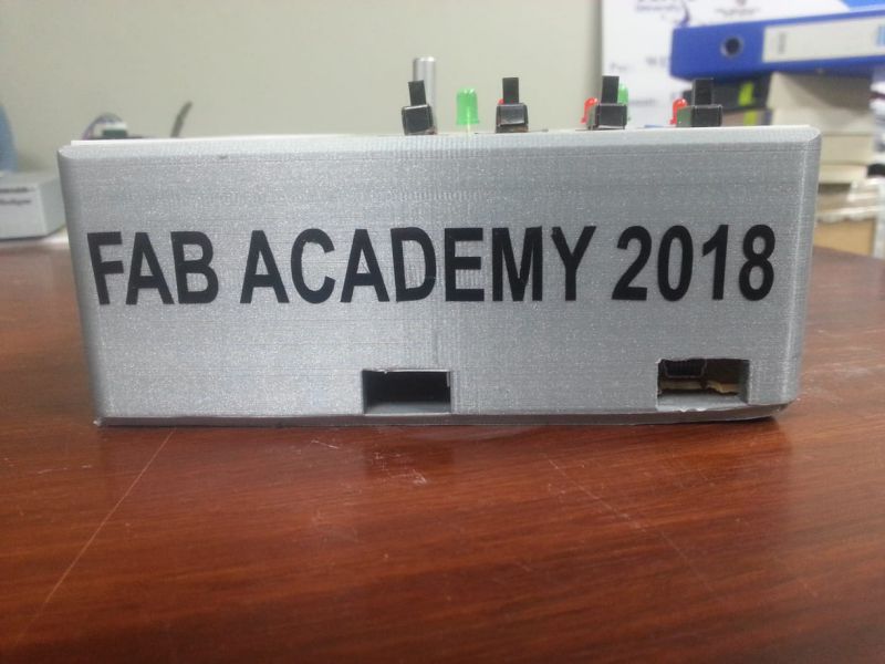
- 3D printing: Casing of the device.
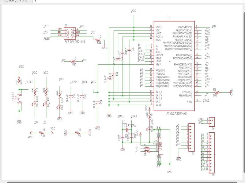
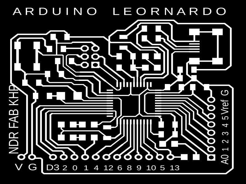
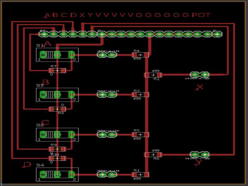
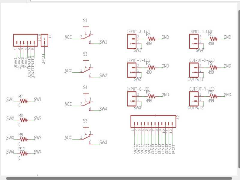
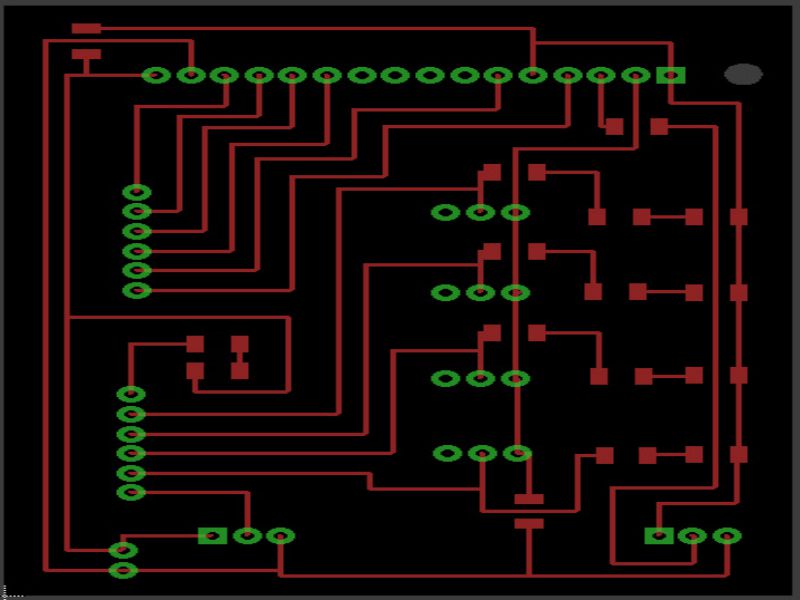
- Electronics production: PCB designing of the atmega32U4 board, I/O board.
- Embedded programming: Programming the atmega32U4 board.
- Computer Controlled Cutting: Laser cutting the acrylic sheet for front panel. Vinyl cutting for labeling the input/output components.
- Input Devices: Controlling the tasks through sliding buttons.
- Output Devices:Displaying the tasks on LCD.
Materials required:
- LCD (16X2)
- Rotary Encoder
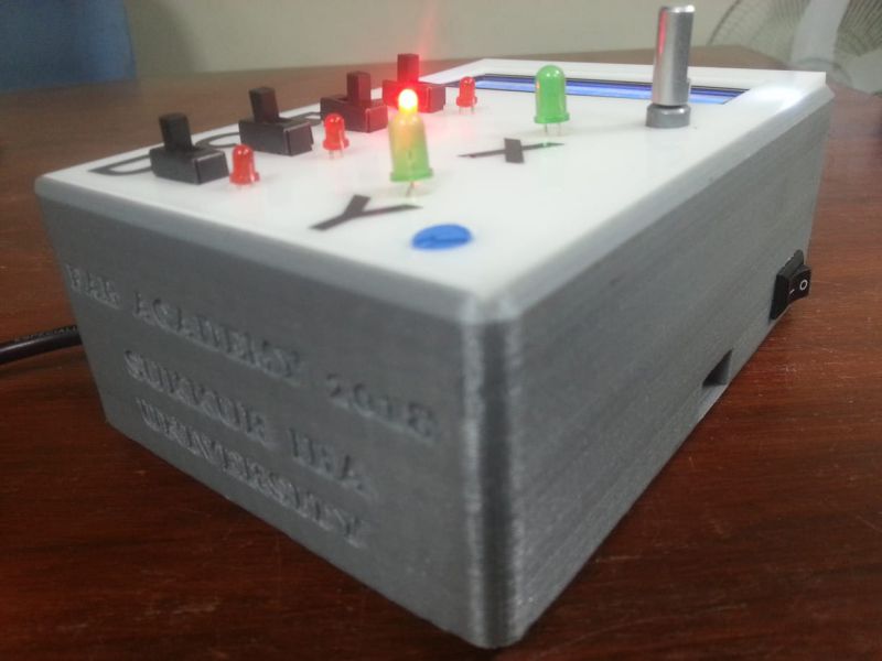
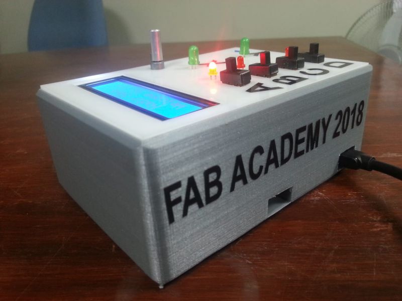
- 3D printed casing
- Acrylic sheet laser cutted for front panel
- Microcontroller based controlling circuit (Atmega32U4 Microcontroller)
- LEDs for Outputs, and for power and high input indicator
- Few SMD resistors of 1205 package
- Few SMD capacitors of 1205 package
- SPDT slider switches
The approximate cost of the components/materials used in project:
| Components | (Quantity of components)* (Price of components in USD) |
Total Price in USD |
|---|---|---|
| 16X2 LCD | 1*2 | $2 |
| Rotary encoder | 1*1.3 | $1.3 |
| PLA 3D printed material (100 g) | 1*2.3 | $2.3 |
| Acrylic sheet | 1*0.5 | $0.5 |
| Atmega32U4 microcontroller | 1*4.7 | $4.7 |
| LEDs | 10*0.1 | $1 |
| Resistors | ~20*0.1 | $2 |
| Capacitors | ~10*0.1 | $1 |
| SPDT slider switches | 4*0.8 | $ 3.2 |
| Total Cost | $ 18 |
Process:
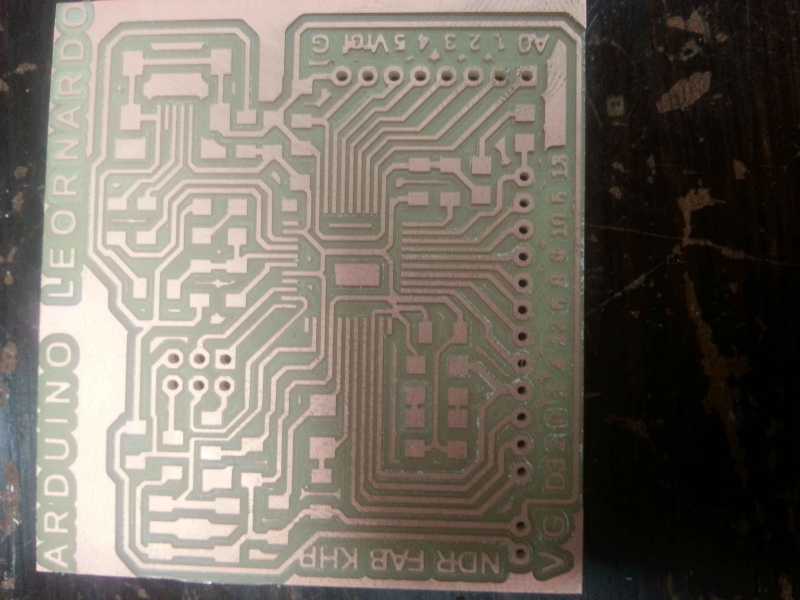
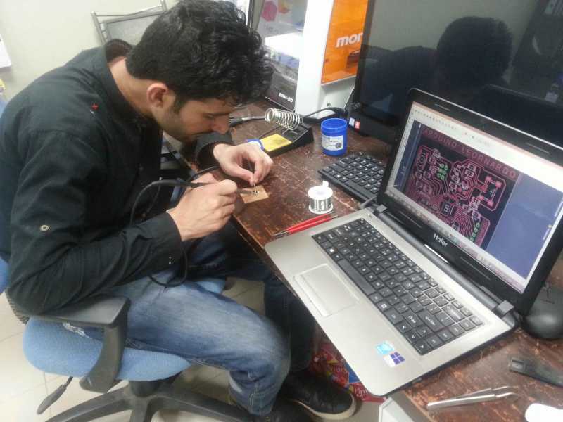
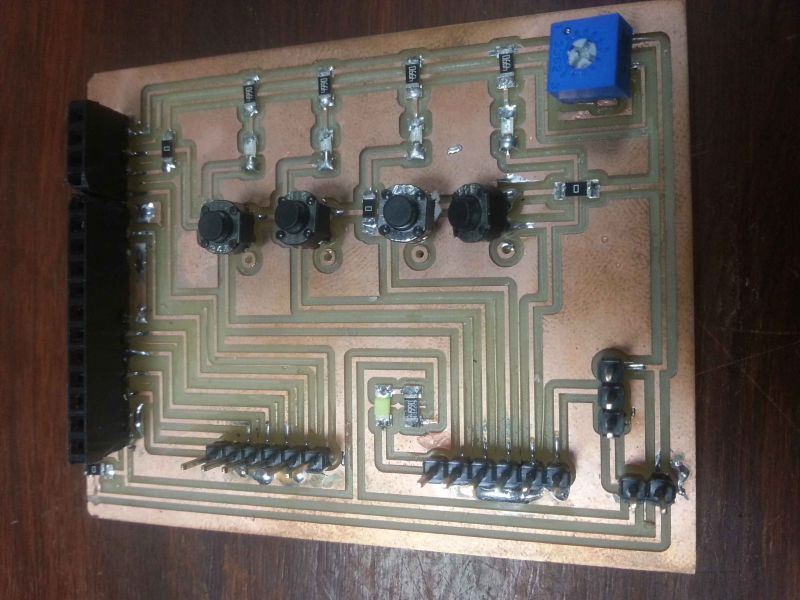
1. Electronics part (Printed Circuit Boards)
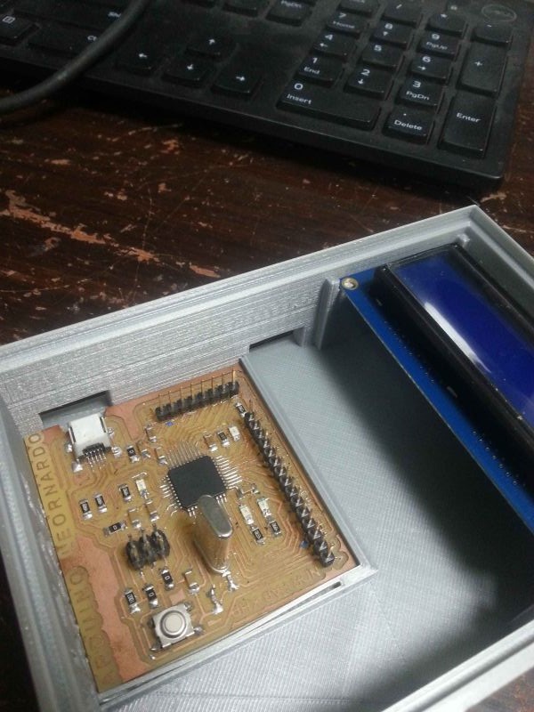
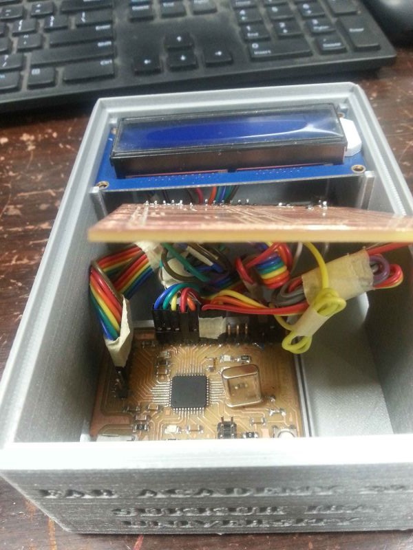
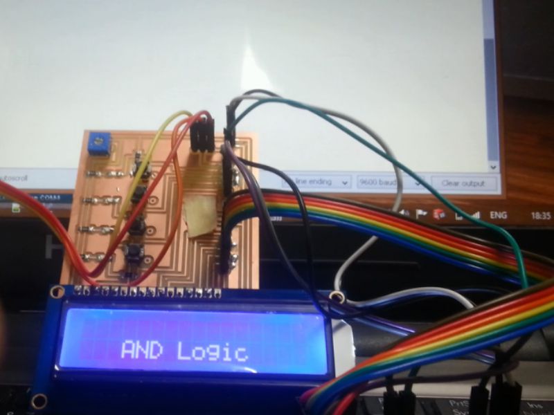
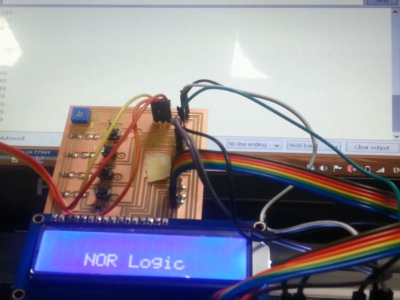
Atmega32U4 board is the main microcontroller of this project, which is programmable by user of the device. I programed all the basic tasks in mt designed leonardo board. And, for input/ output, I have designed another PCB board, which is connected to leonardo board through jumper wires.

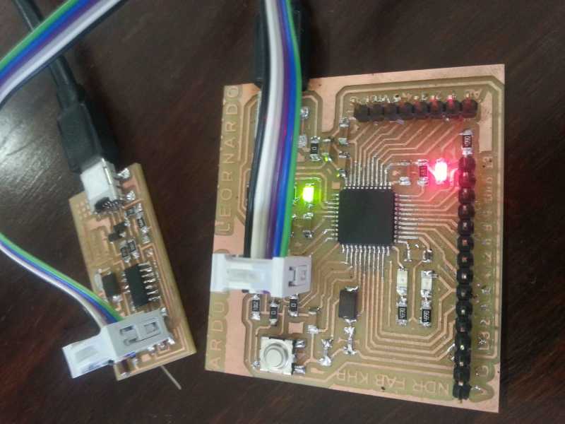
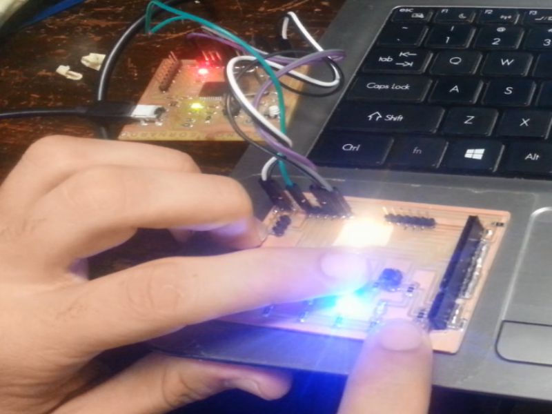
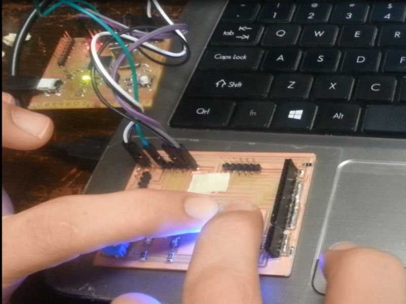
Testing board, (for experimental purpose, not finalized)
Download all files of Electronics Production of final project from here
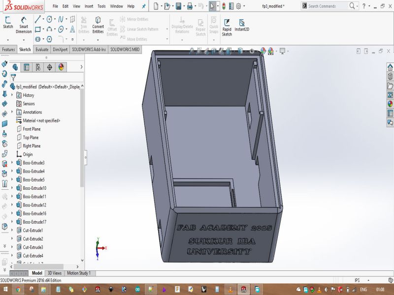
2. Computer Aided Design
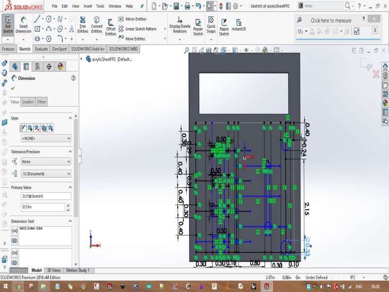
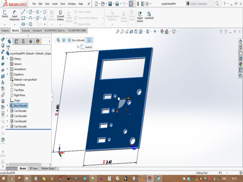
I designed the final model of the project's casing on SolidWorks. For Front panel sheet, I designed its model on SolidWorks then laser cut it on acrylic sheet of 3mm.
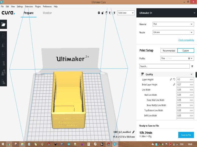
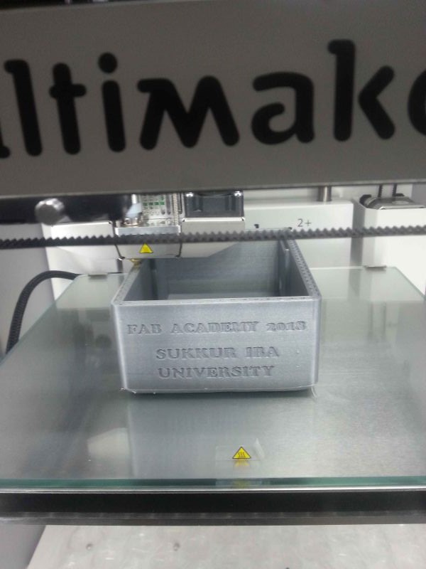
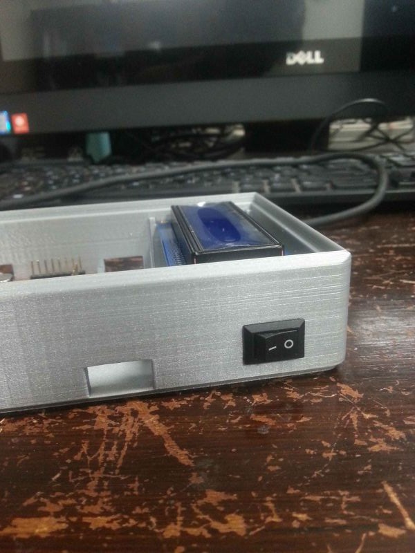
3. 3D printing of the casing
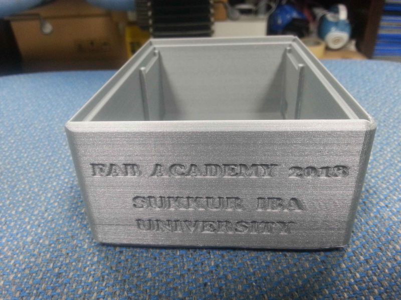
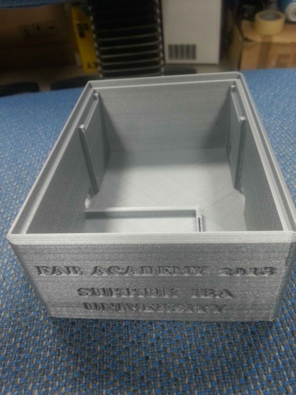
Download files of 3D design of final project from here
4. Laser cut of the front sheet
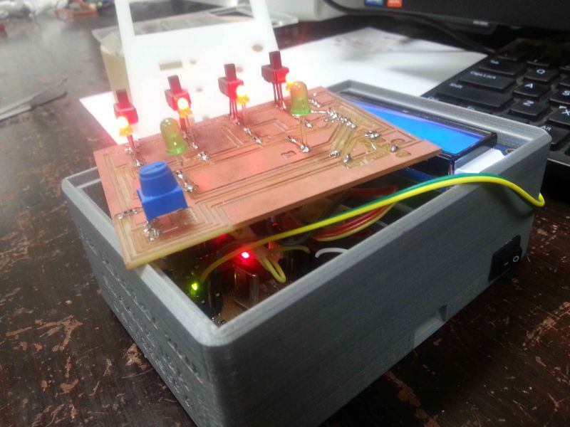
For front panel of the 3D printed box, I have designed a sheet for user interface of the project, where I have intended to label the inputs/outputs by sticker cut in Vinyl cutter.
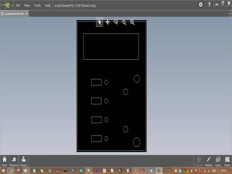
Download files of Laser cutting for front panel of final project from here
5. Vinyl cutting
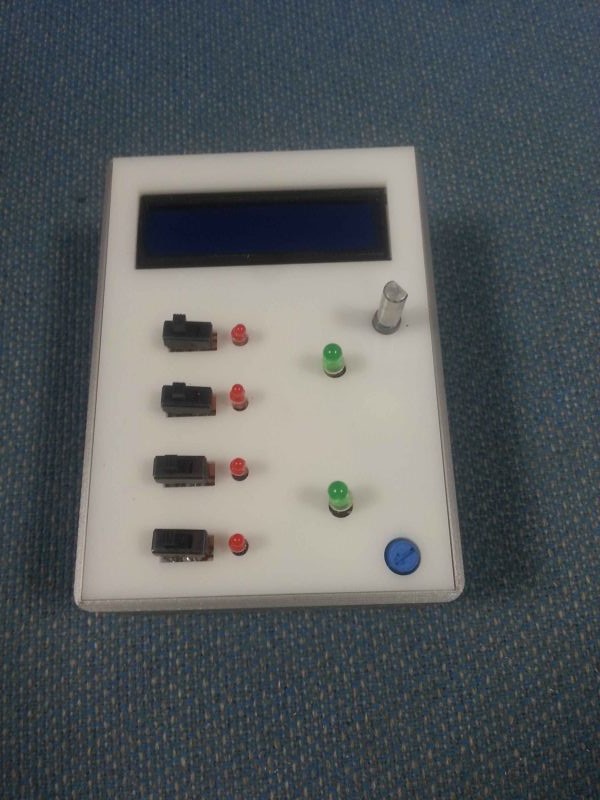
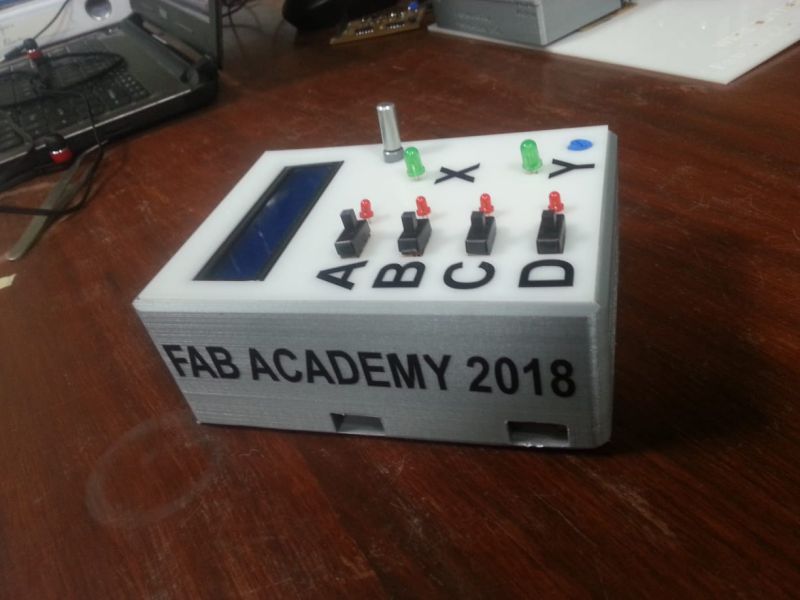
For labeling the input switches (i.e. A, B, C, D), and output LEDs (i.e. X, Y), I used stickers which I cut in vinyl cutting machine.
6. Embedded programming
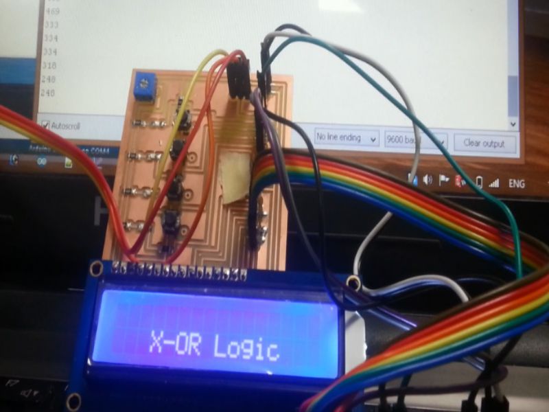
Testing codes, performing different tasks
I checked each and every basic gate's code in microcontroller, that was working pretty well. Also, checked and tested each tasks label displayed on LCD. In testing phase, I used a 10K potentiometer, and assigned each task an specific range of values.
Final Demo
Download all files from here

This work is licensed under a Creative Commons Attribution-NonCommercial 4.0 International License.