


Embedded Programming
Embedded Programming is the dominant methodology of for programming the microcontrollers. Embedded programming involves the programming small computers that tend to drive devices. Here, this week is all about embedded programming.
Assignment of the week:
Group Assignment
Following are a few different microcontroller architectures available in the market
- 8051
- ARM
- AVR
- PIC
They are differentiated on the basis of their operation at the lower level. While 8051, AVR and PIC come in 8-bit, 16-bit and 32-bit, the ARMs generally come in 32-bit and even 64-bit. The 8051, AVR and PIC work closer with the I/O peripherals and can be lower power and faster as a result.
The Intel MCS-51 (also known as 8051) is a CISC architecture. These are available in 8-bit, 16-bit and 32-bit microcontrollers. 8051 silicon IP cores are typically smaller size, lower power compared to ARM Cortex-M and MIPS processors. They are used in everything from USB flash drives to washing machines and complex wireless communications systems-on-chip.
AVR is a family of microcontrollers developed by Atmel that use the RISC processors. AVR are most commonly used in the Arduino line of open source board designs. These are available in 8-bit tinyAVR, megaAVR and XMEGA. AVR32 is the 32-bit offering, which was intended to compete with ARM processors. These are not compatible with the original ARM and include additional SIMD and DSP instructions as well as audio and video processing features. One of the nice features of most AVR models is that they can reserve a bootloader region to store re-programming code. The code can then re-program through any interface available.
PIC stands for Peripheral Interface Controller. It is a family of microcontrollers developed by Microchip with a wide variety of options available. They are not strictly RISC processors as they differ very slightly in their operation. The product range includes the 8-bit PIC10, PIC12, PIC 16 and PIC18, the 16-bit PIC24 and dsPIC and the 32-bit PIC32MX, PIC32MZ, PIC32MM and PIC32MK. The 8-bit range focuses on lower cost, the dsPIC focuses on digital signal processing. The PIC32 series of microcontrollers uses the MIPS32-M4K core technology, which is a 32-bit RISC architecture. MIPS is a direct competitor to the ARM processors covering all types of applications in home entertainment, embedded and networking products, mobile, wearable and IoT devices.
RISC (Reduced Instruction Set Computer) performs more instructions with lower cycles as compared to CISC architectures. CISC processors include the Intel x86 and 8051, Motorola 68000 and Zilog Z80 families.One of the key advantages to RISC is the load/store architecture which separates memory access and ALU operations (arithmetic logic unit). This improves cost, power consumption and heat dissipation, making them desirable for light, battery operated devices. RISC processors can be found in the ARM, AVR and PIC microcontrollers.
Individual Assignments
In this task, I used atmega32U4 microcontroller in my circuit board. The datasheet can be found here.
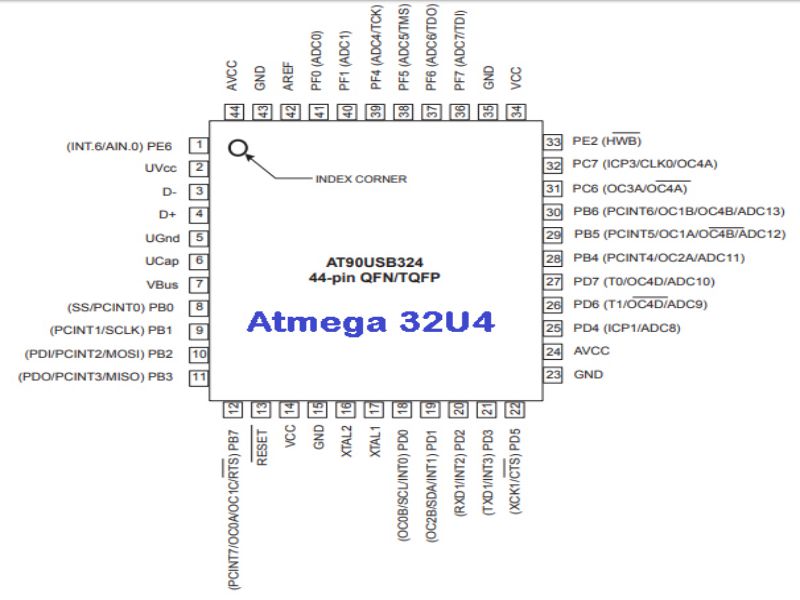
Few points which I read in datasheet are:
- Atmega32U4 is a low power CMOS 8-bit mocrocontroller based on the AVR enhanced RISC architecture.
- By executing powerful instructions in a single clock cycle, the ATmega32U4 achieves throughputs approaching 1 MIPS per MHz allowing the system designer to optimize power consumption versus processing speed.
- Port B (PB7...PB0): Port B is an 8-bit bi-directional I/O port with internal pull-up resistors.
- Port B has better driving capabilities than the other ports.
- Port C (PC7,PC6):Port C is an 8-bit bi-directional I/O port with internal pull-up resistors.
- In port C only bits 6 and 7 are present on the product pinout.
- Port D (PD7...PD0):Port D is an 8-bit bi-directional I/O port with internal pull-up resistors.
- Port E (PC6,PC2):Port E is an 8-bit bi-directional I/O port with internal pull-up resistors.
- In port E only bits 6 and 2 are present on the product pinout.
- Port F (PF7...PF4, PF1,PF0):Port F serves as analog inputs to the A/D Converter.
- Port F also serves as an 8-bit bi-directional I/O port, if the A/D Converter channels are not used.
- In port F bits 2 and 3 are not present on the product pinout.
- Port F also serves the functions of the JTAG interface.
- D- : Pin no. 3. USB Full speed / Low Speed Negative Data Upstream Port. Should be connected to the USB D-connector pin with a serial 22 Ohms resistor.
- D+ : Pin no. 4. USB Full speed / Low Speed Positive Data Upstream Port. Should be connected to the USB D+connector pin with a serial 22 Ohms resistor.
- UGND: Pin no. 5. USB Pads Ground.
- UVCC: pin no. 2. USB Pads Internal Regulator Input supply voltage.
- UCAP: Pin no. 6. USB Pads Internal Regulator Output supply voltage. Should be connected to an external capacitor (1µF).
- VBUS: Pin no. 7. USB VBUS monitor input.
- RESET: Pin no. 13. Reset input. A low level on this pin for longer than the minimum pulse length will generate a reset, even if the clock is not running.
- XTAL1: Pin no. 17. Input to the inverting Oscillator amplifier and input to the internal clock operating circuit.
- XTAL2: Pin no. 16. Output from the inverting Oscillator amplifier.
- AVCC: Pin no. 24 and 44. AVCC is the supply voltage pin (input) for all the A/D Converter channels. If the ADC is not used, it should be externally connected to VCC. If the ADC is used, it should be connected to VCC through a low-pass filter.
- AREF: Pin no. 42. This is the analog reference pin (input) for the A/D Converter.
- VCC: Pin no. 14 and 34
- GND: Pin no. 15, 23, 35 and 43
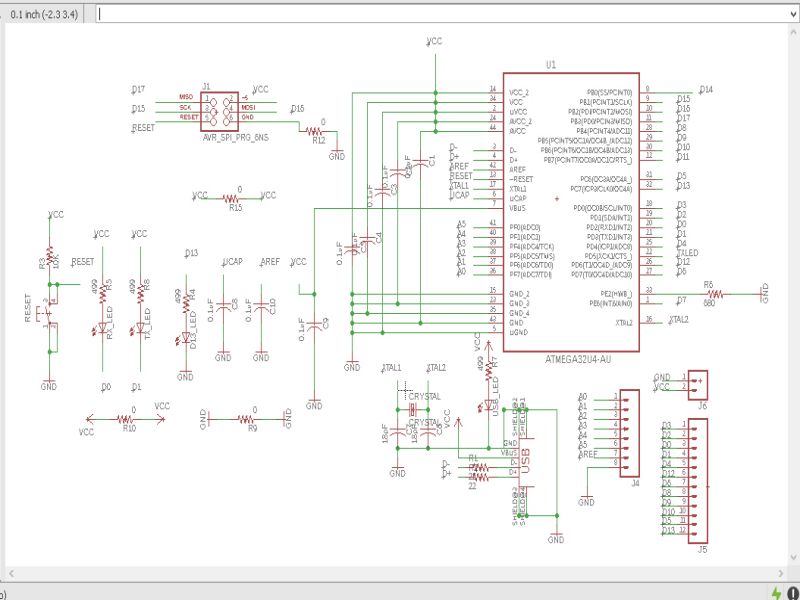
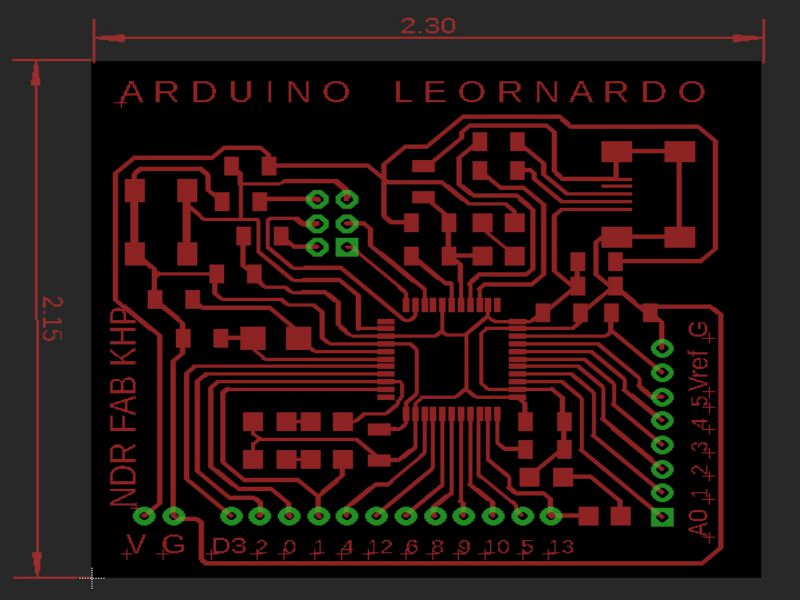
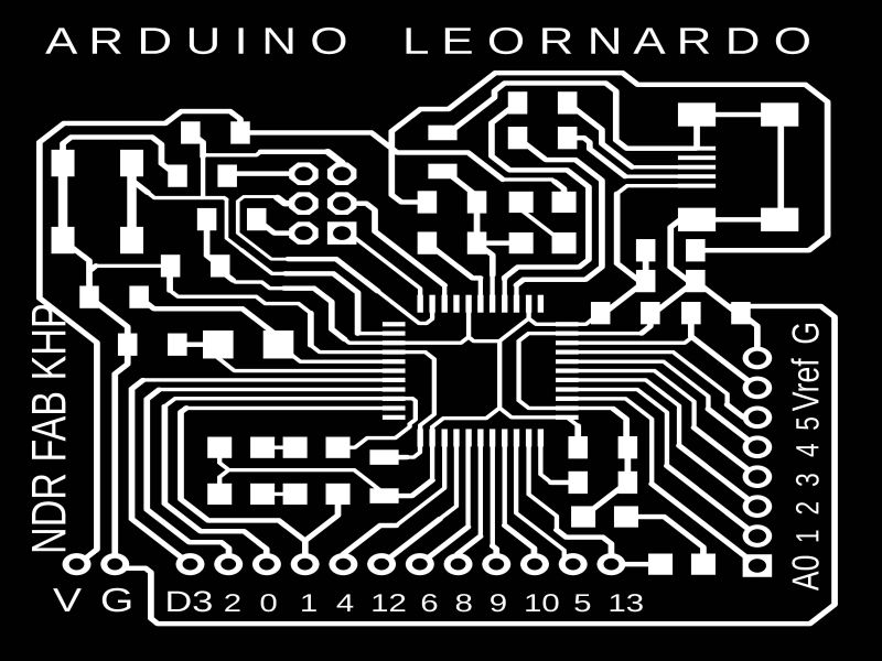
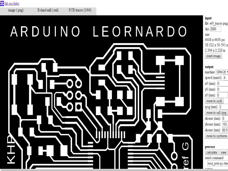
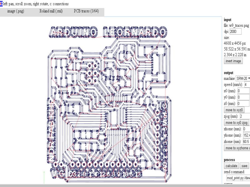
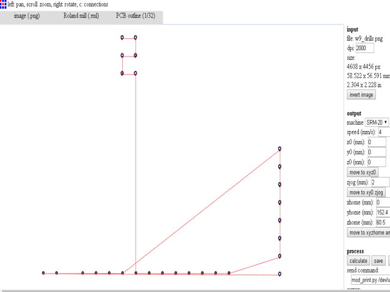
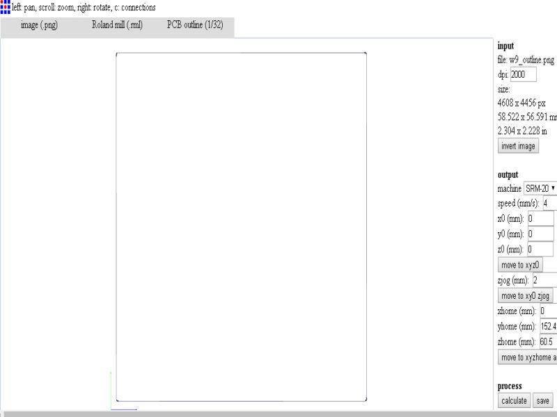
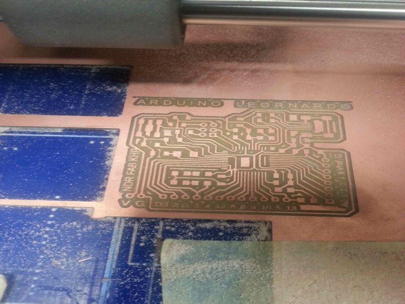
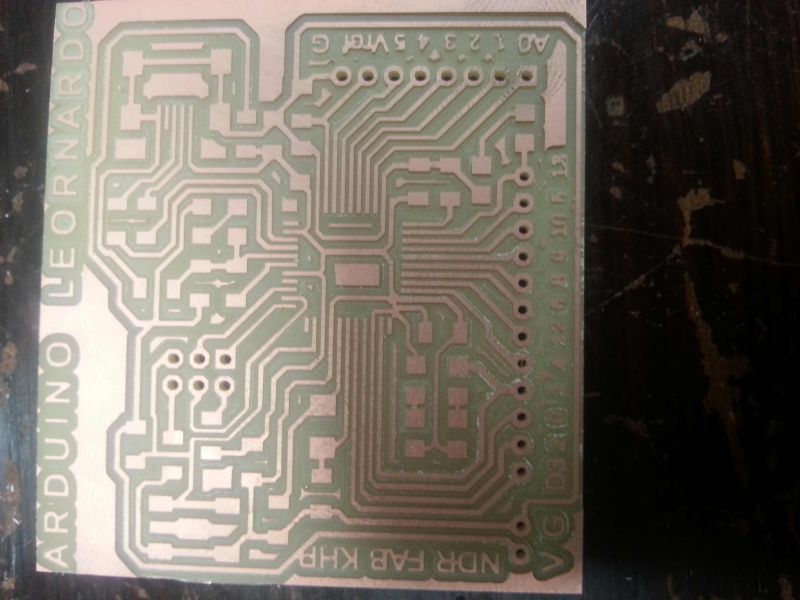
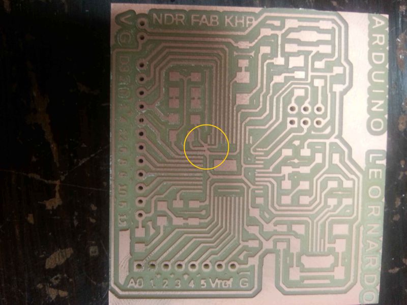
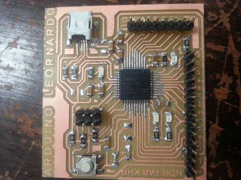
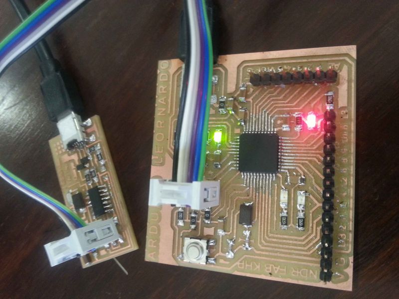
In this week task I designed a board for 'Arduino Leonardo' by using Atmega32U4 as main IC. To design this, I searched many schematics for board and read datasheet of the main Ic thoroughly, and, tried different sketches on page for connectivity and I/Os. In this board, I will practice for my final projects logic gates. The schematics and other necessary images are listed below:


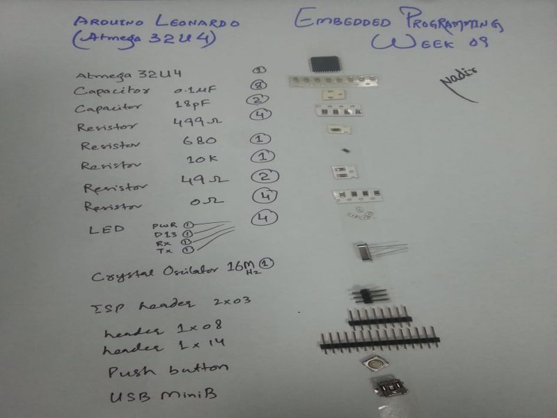
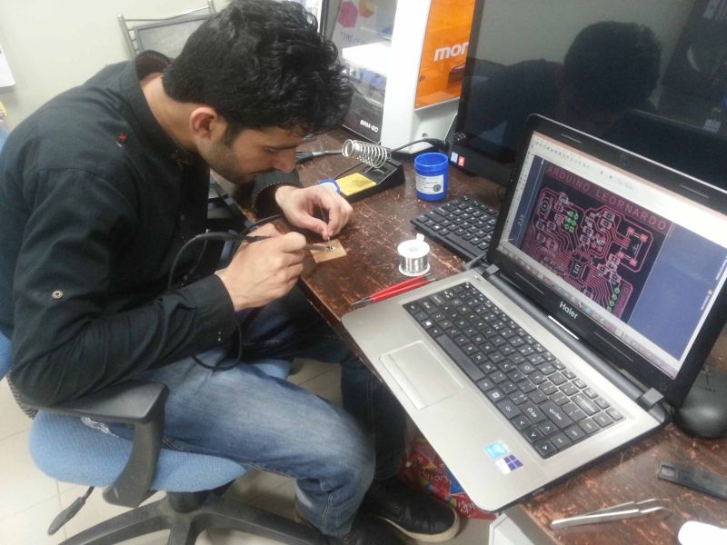
Soldering the board
Soldering is became my favourite job. Now, I love soldering the tiny components. Here, in this board, it was my first time in FabLab to solder an IC which comprises of 44 pins, yes, I am talking about 'Atmega32U4'. For be on safe side to not connect wrong connections of soldering the IC, I used "wax", which prevents paths to not connect to their neighbour paths.
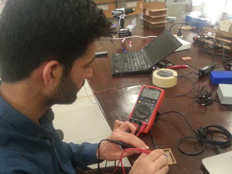
Debugging the board
This is the time for checking the board, that which components are getting proper source and which are not. Here, for this process I used digital multimeter. I check the connections of all ground parts in the board, then checked connections of VCC, in the same way checked the connections of each and every pin of atmega32U4 IC. I found all connections in good health, no two different wires/paths were connected to each other. So, the I proceed the next step that was Up the circuit, or in other words to burn bootloader the circuit board through a programmer.
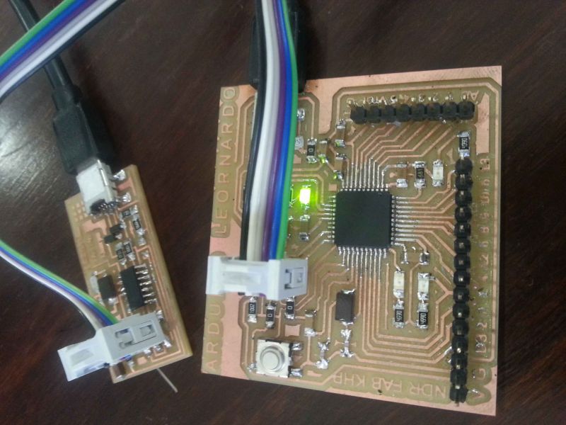
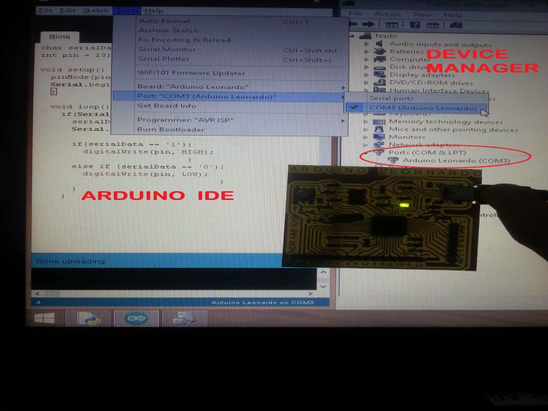
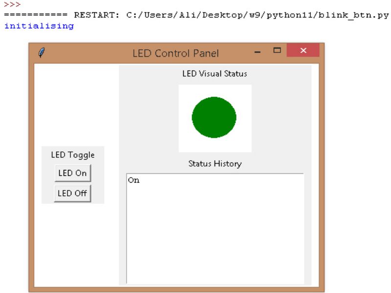
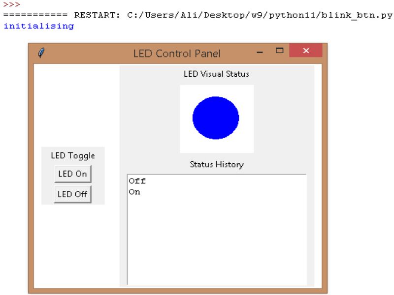
Here I created a GUI (Graphical User Interface) for LED blink status using python. The codes of Python and Arduino are given below:
Arduino code for blinking of the LED
// Nadir Ali
// FABLAB Khairpur Sindh Pakistan
// Week 09, Embedded Programming
// FAB Academy 2018
char serialData;
int pin = 13;
void setup() {
pinMode(pin,OUTPUT);
Serial.begin(9600);
}
void loop() {
if(Serial.available() > 0){
serialData = Serial.read();
Serial.print(serialData);
if(serialData == '1'){
digitalWrite(pin, HIGH);
}
else if (serialData == '0'){
digitalWrite(pin, LOW);
}
}
}
Python code for GUI of blinking of the LED
# Nadir Ali
# FABLAB Khairpur Sindh Pakistan
# Week 09, Embedded Programming
# FAB Academy 2018
from tkinter import *
root = Tk() #Makes the window
root.wm_title("LED Control Panel") #Makes the title that will appear in the top left
root.config(background = "#FFFFFF") #sets background color to white
#widgets:
#Left Frame and its contents
leftFrame = Frame(root, width=200, height = 600)
leftFrame.grid(row=0, column=0, padx=10, pady=2)
#Right Frame and its contents
rightFrame = Frame(root, width=200, height = 600)
rightFrame.grid(row=0, column=1, padx=10, pady=2)
#Canvas for drawing circles
circleCanvas = Canvas(rightFrame, width=100, height=100, bg='white')
circleCanvas.grid(row=1, column=0, padx=10, pady=2)
#Logging LED on/off status
LEDLog = Text(rightFrame, width = 30, height = 10, takefocus=0)
LEDLog.grid(row=3, column=0, padx=10, pady=2)
#Labels
firstLabel = Label(leftFrame, text="LED Toggle")
firstLabel.grid(row=0, column=0, padx=10, pady=2)
secondLabel = Label(rightFrame, text="Status History")
secondLabel.grid(row=2, column=0, padx=10, pady=2)
thirdLabel = Label(rightFrame, text="LED Visual Status")
thirdLabel.grid(row=0, column=0, padx=10, pady=2)
#Drawing circles for the LED visual status
def grnCircle():
circleCanvas.create_oval(20, 20, 80, 80, width=0, fill='green')
LEDLog.insert(0.0, "On\n")
def whtCircle():
circleCanvas.create_oval(19, 19, 81, 81, width=0, fill='blue')
LEDLog.insert(0.0, "Off\n")
import serial
import time
#Open serial port to the board
arduino = serial.Serial(port = 'com3', baudrate = 9600, writeTimeout = 0)
time.sleep(1) # waiting for initialization...
print("initialising")
#Turning LED on
def LEDOn():
arduino = serial.Serial(port = 'com3', baudrate = 9600, writeTimeout = 0)
arduino.write('1'.encode())
grnCircle()
#Turning LED off
def LEDOff():
arduino = serial.Serial(port = 'com3', baudrate = 9600, writeTimeout = 0)
arduino.write('0'.encode())
whtCircle()
#LED on/off buttons
newButton = Button(leftFrame, text="LED On", command=LEDOn)
newButton.grid(row=2, column=0, padx=10, pady=2)
newButton = Button(leftFrame, text="LED Off", command=LEDOff)
newButton.grid(row=3, column=0, padx=10, pady=2)
arduino.close() #close serial port
root.mainloop() #loop to update GUI
Learning Outcomes
- Feeling comfortable with designing circuits in Eagle.
- Became bit handy in soldering the small components.
- Learn to create basic GUIs in python.
- Datasheet must be refered before using any component/MCU in designing circuit.
- It requires special attention to sold SMD components.
- Mature placement of the components can reduce the size of the board and also helps to route easily.
- For generating .rml files in 'Fab module', the resolution of exported image must be greater than 1200 dpi, I select 2000 dpi in this circuit.
- Selecting of PCB desgning software also plays a vital role to reduce complexity. Here I used 'Eagle' as I also used it in my previous weeks of electronics circuit designing.

This work is licensed under a Creative Commons Attribution-NonCommercial 4.0 International License.