
|
| Sukkur IBA University Merit, Quality, Excellence |
WEEK-11
Input Devices
Lecture & Recitaton of a Week:
Lecture on 4th of April, 2018: Input Devices by Neil Gershenfeld
Recitation on 9th of April, 2018: Circular innovation challenge by Eric King
Tasks for a Week
- individual assignment: measure something: add a sensor to a microcontroller board that you have designed and read it
- group assignment: measure the analog levels and digital signals in an input device
Individual Assignment
As electronic engineer this week is quite easy for me, the only new thing for me is to work on python language which I never work before. I made two circuit boards in this week one is to measure temperature and second one is to detect the presence of light.
Hello Temerature Board
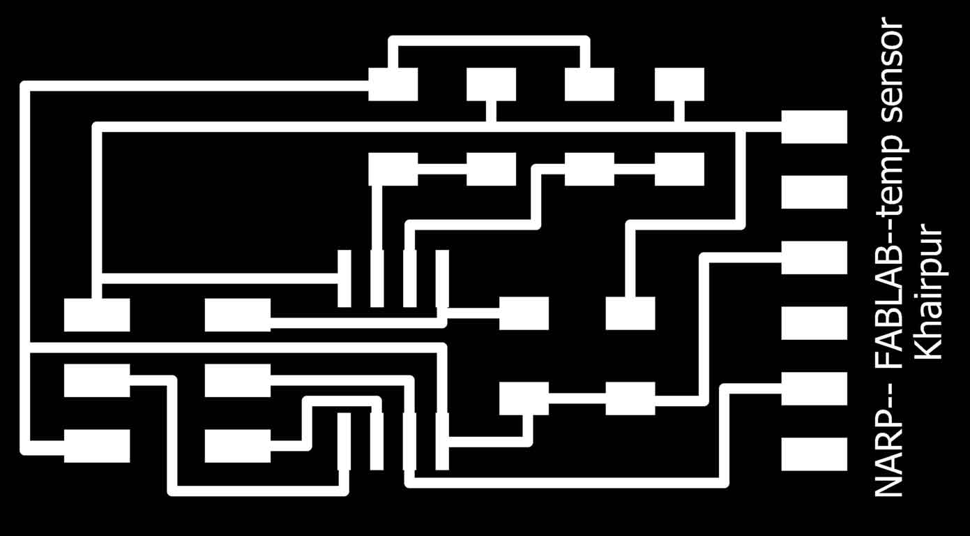
I redraw this board from hello temp board which is available in Input Devices lecture. The board is based on attiny45 controller and a temperature sensor "NTC THERMISTOR" with some supporting circuitry.
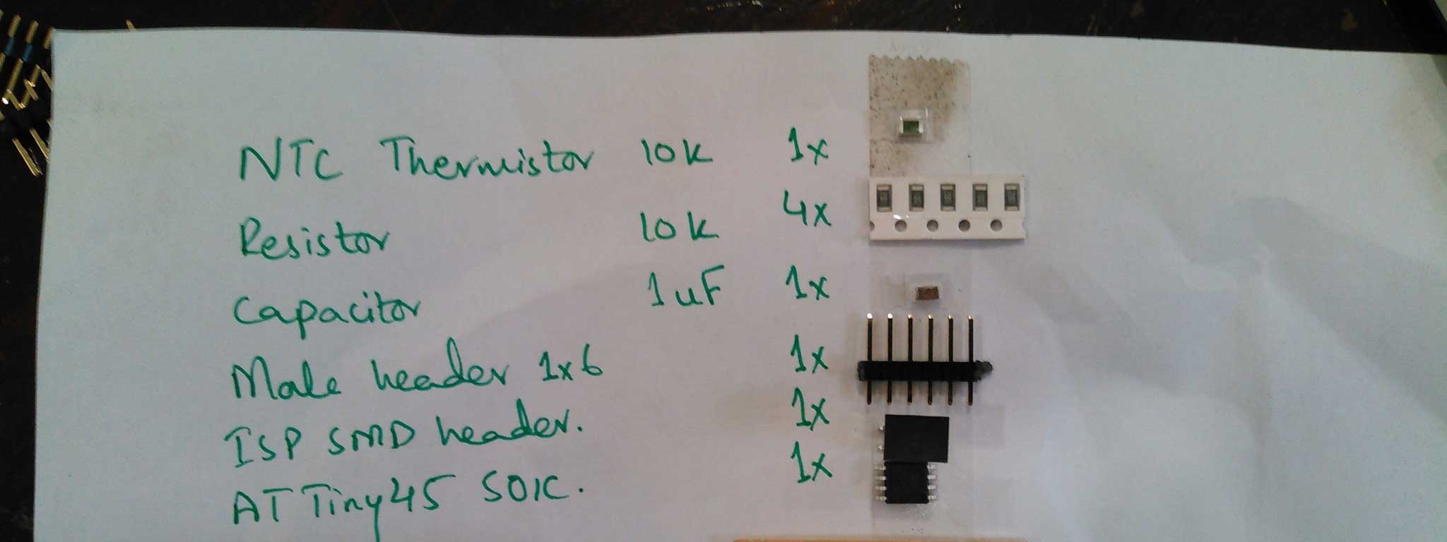
List of Components:
- NTC THERMISTOR 10K OHM 10% 1206 1x
- Resistor 10k SMD 1206 4x
- Capacitor 1uF 50V 1206 1x
- 1 SMD male header 1x61x
- ISP SMD header1x
- ATTiny45 SOIC Packaging1x
Component List
PCB Designing
For PCB designing I worked on Eagle 7.5 (an introduction of this software is mentioned in Electronic Design Week). First I made a schematic:
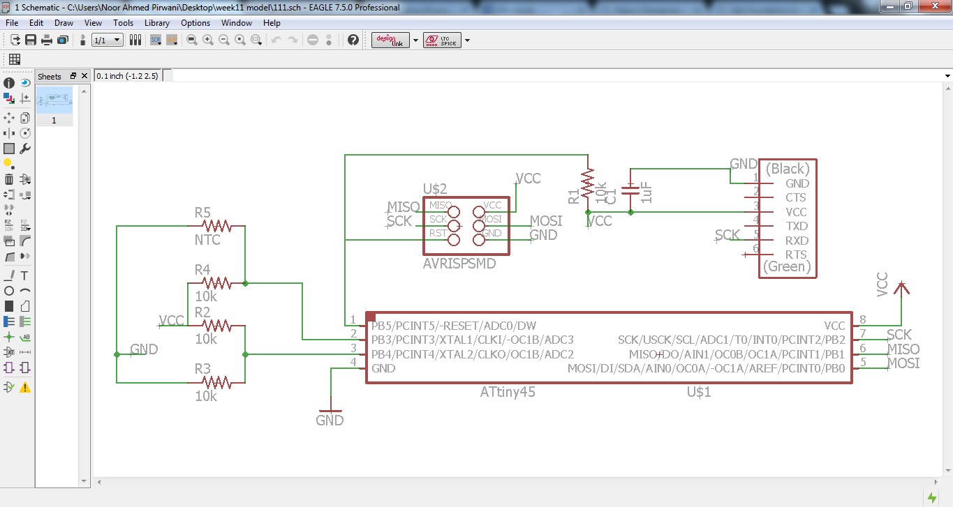
Temp Sensor Schematic
then I generate PCB board and route it.
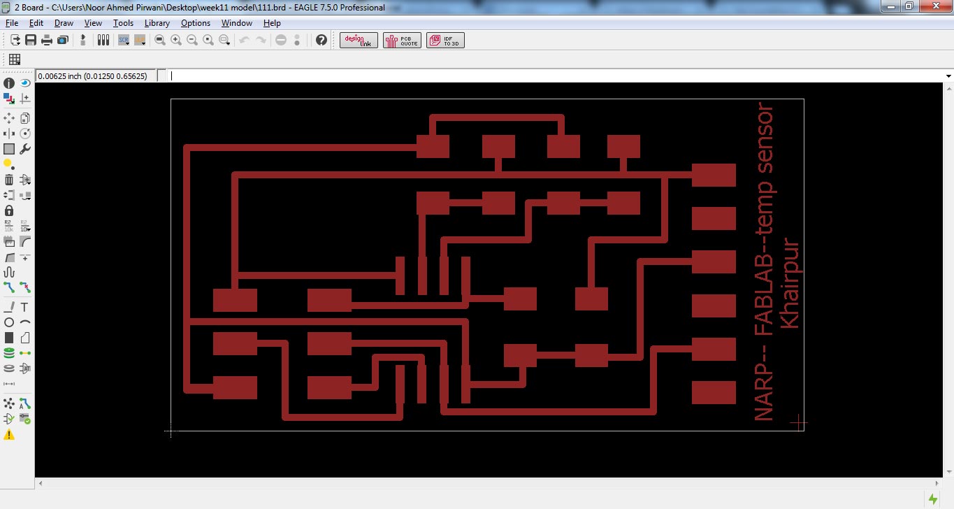
PCB Design
Generating .RML Files
For generating RML files, first I need my PCB design in .png format for that I export my PCB design in .png while setting up 2000 dpi and Monochrome
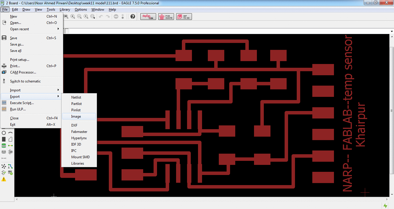
Exporting PCB design into .png format
.png is processed in Paint for making seperate files for traces and outline of a PCB design (in a case of drill holes in PCB one more file is made)
PCB traces

PCB Outline
after making traces and outline of a pcb I used fabmodules to generate RML files of both traces and outline, all important settings are mentioned in a pictures below, for detailed fabmodules settings visit Electronics Production Week
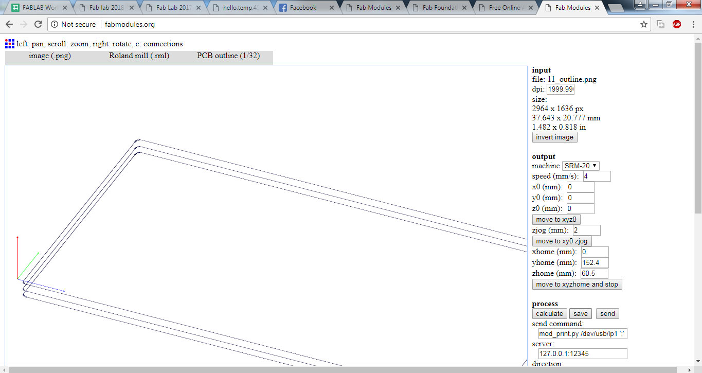
generating .rml file of PCB outline
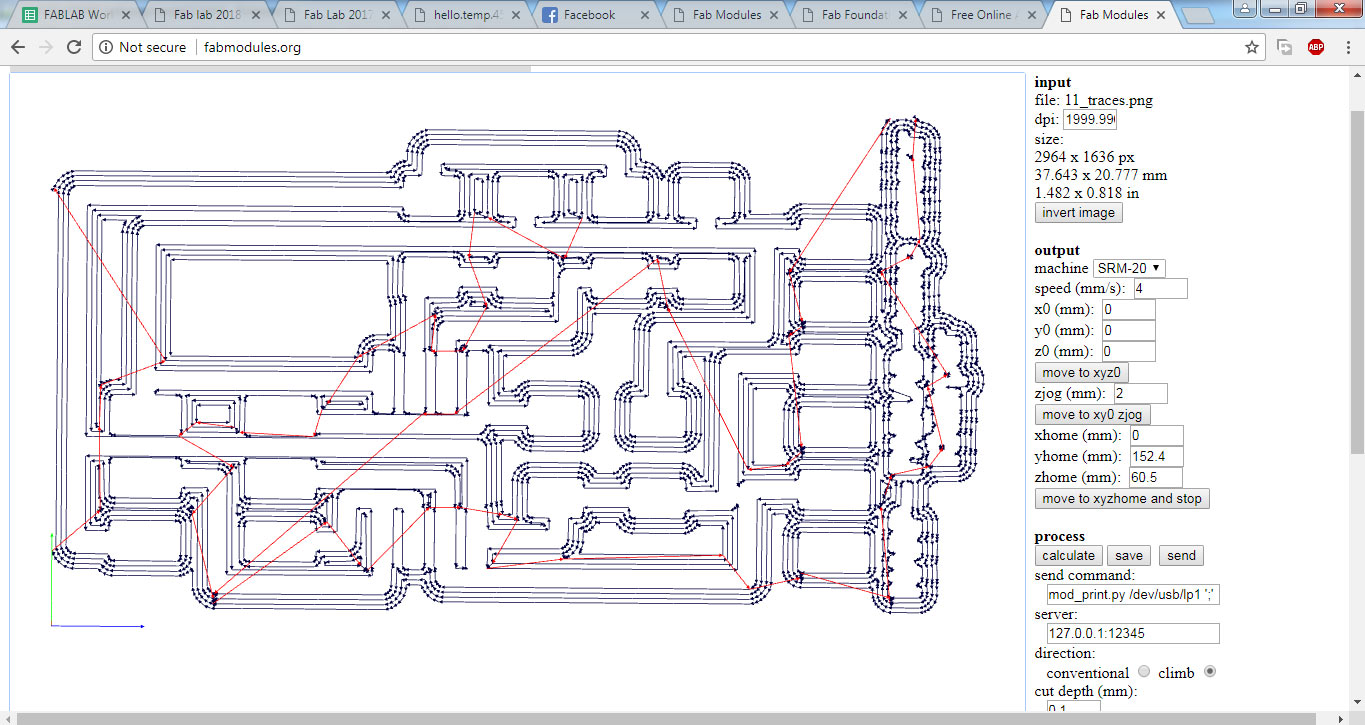
generating .rml file of PCB traces
Milling and Soldering
.rml files are given to Roland SRM-20 for milling, 1/32 drill bit is used for cutting outlines and 1/64 bit drill is used to make a trace on a board and here is the result.
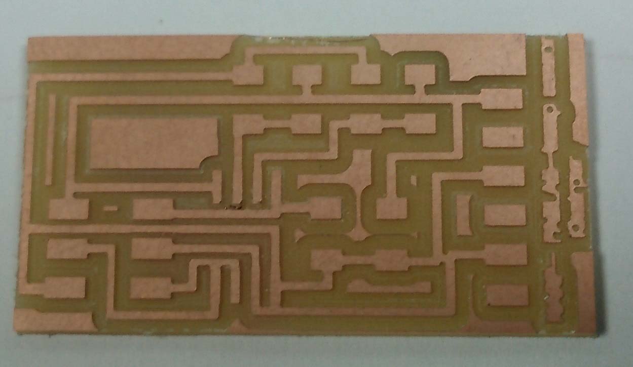
Printed Circuit Board
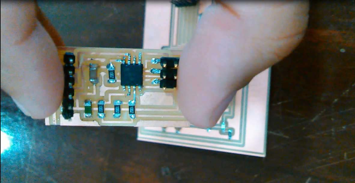
Soldered Components on a board
Programming the board
To program a board I need an ISP programmer, I made one developer board in Electronics Production Week so I used it with my temperature sensing board.
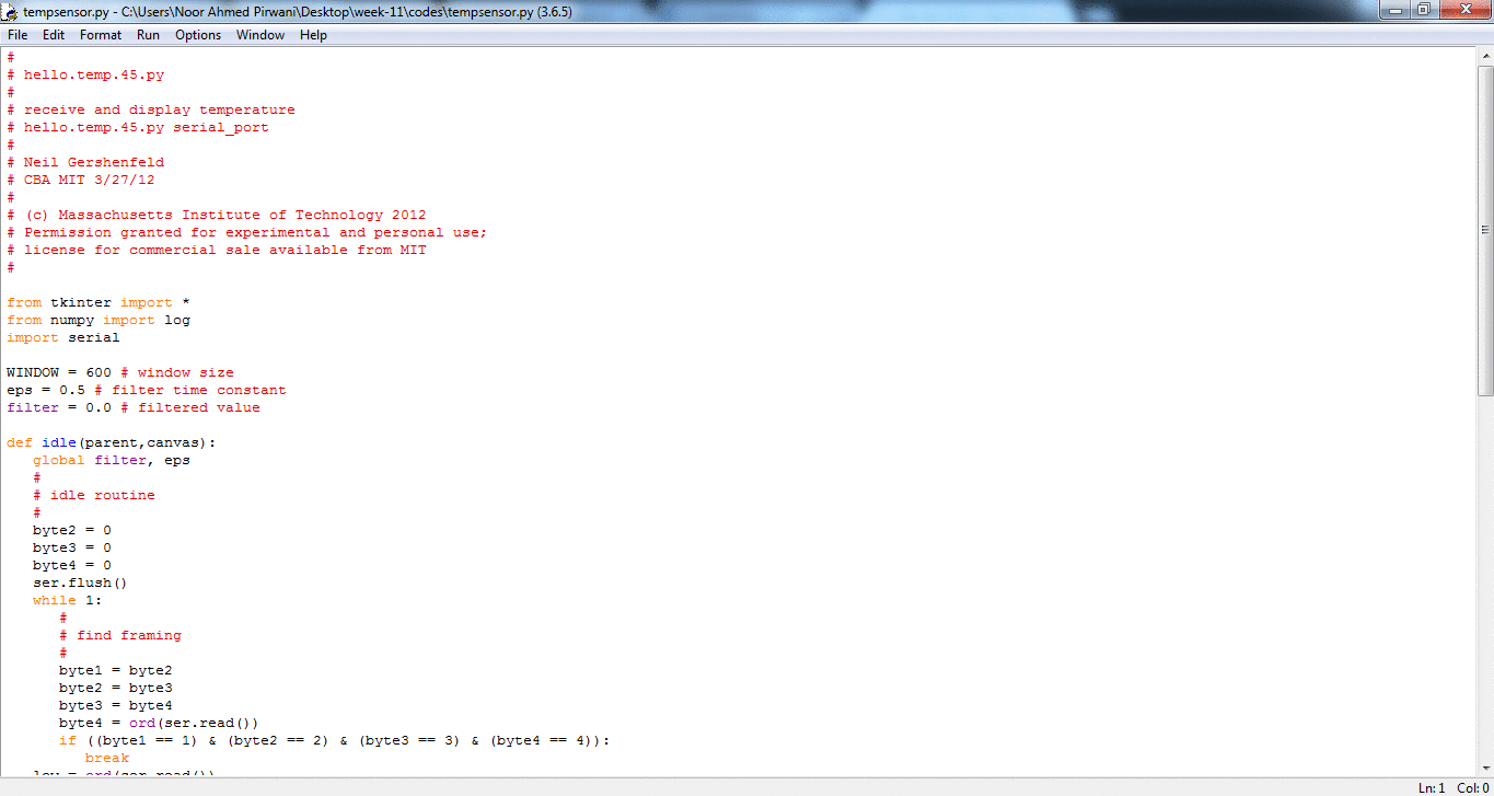
I am using Arduino IDE for programming my board. For setting up Arduino IDE to work with FabISP I mentioned in detail in Embedded Programming Week. I programmed my board with Neil's hello.temp.45.c code because it supports Neil's Python code (Python is new for me, in next board I did some changes in my board and code). Before programming the board first it is required to burn bootloader in it.
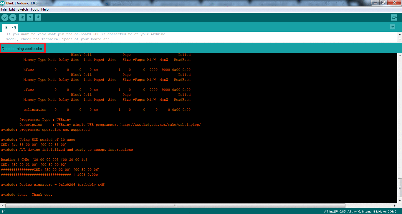
Burning bootloader and uploading code in Arduino IDE
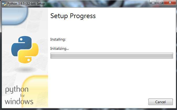
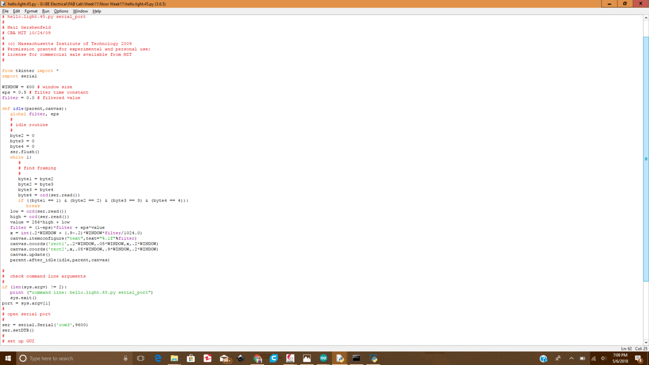
Now to see the results on serial monitor first I installed Python 3.6.5
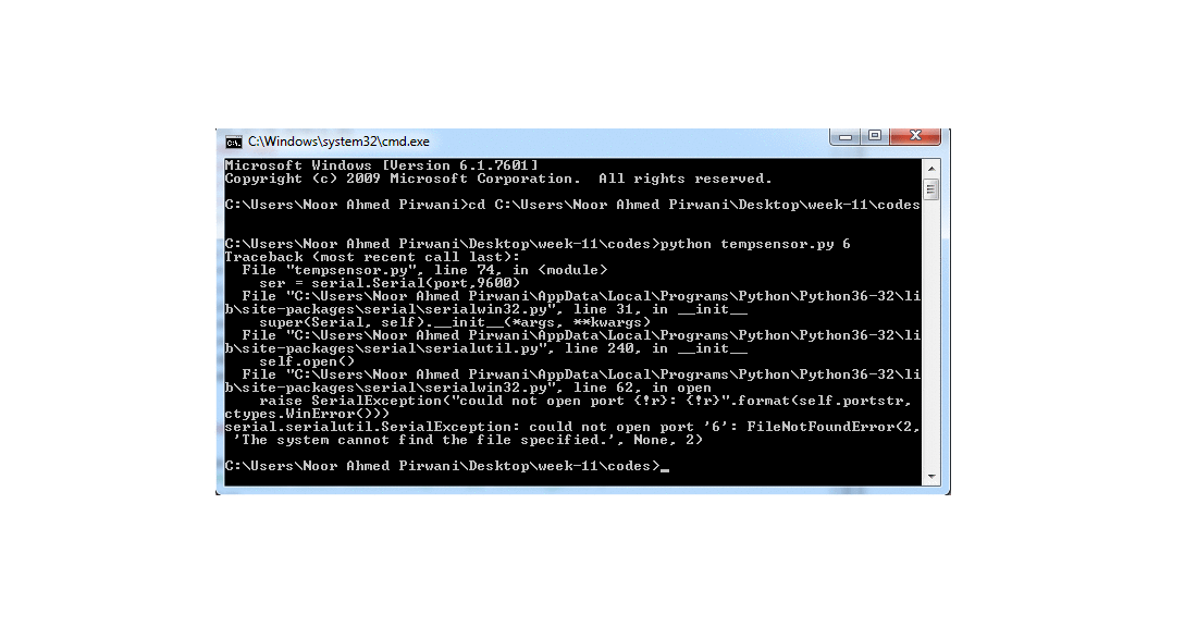
I just copy paste the Neil's code in python but it didn't work. and got some errors.
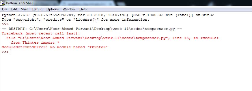
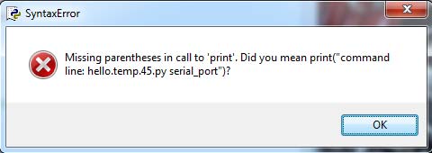
After little bit search on internet I understands that the errors are because of python version, so I make some changes I just change Tkinter to tkinter apply parenthesis where missing and install numpy and serial modules.
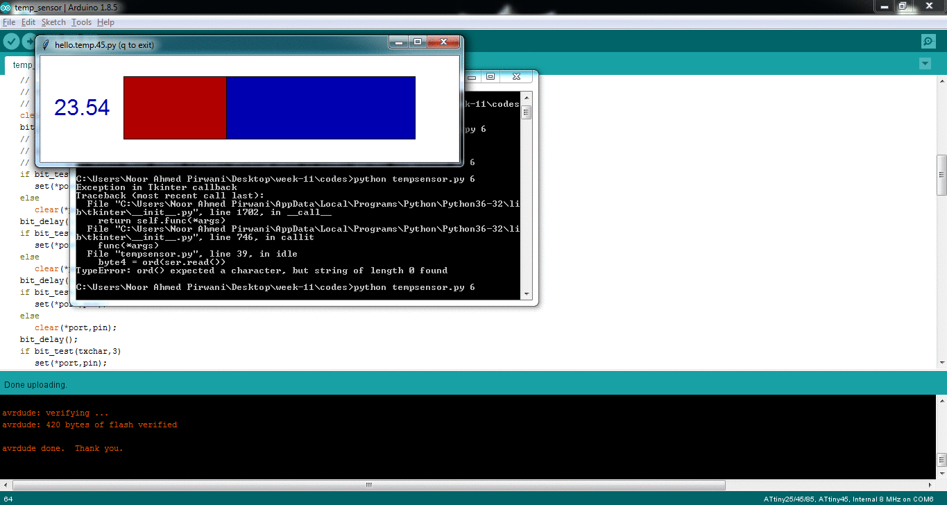
Python code and successfully Run window
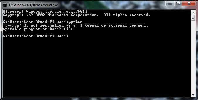
I am using command prompt to run the python.Below I mention steps how to work on python using command prompt
- First check either Python is present in path or not
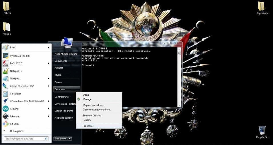
- Now goto System properties by clicking on Start > right click on computer and select Properties > click on Advanced system settings and select Environment Variables. Save the python Address in path window in Environment variables
- Now to check python present in path or not:
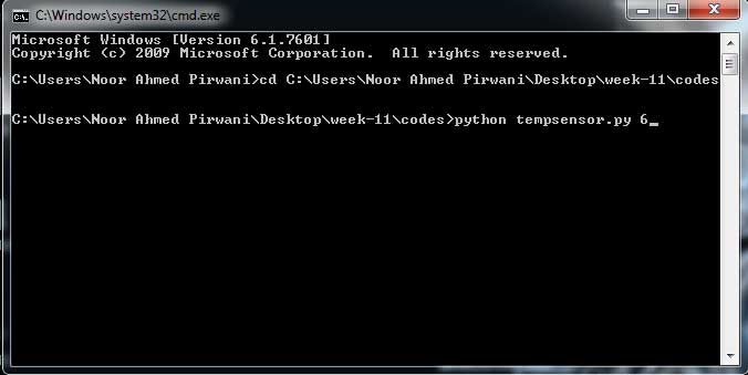
- Now I run the command in command prompt python tempsensor.py 6 it says run python file and get data from com6
- I got error as I never set COM port in code. So I write COM port address in serial command
- Here are the results of tempearature sensor which is received via FTDI Cable
Light Sensing Board
I redraw this board from hello light board which is available in Input Devices lecture. The board is based on attiny45 controller but I redraw it with attiny44 board.
List of Components:
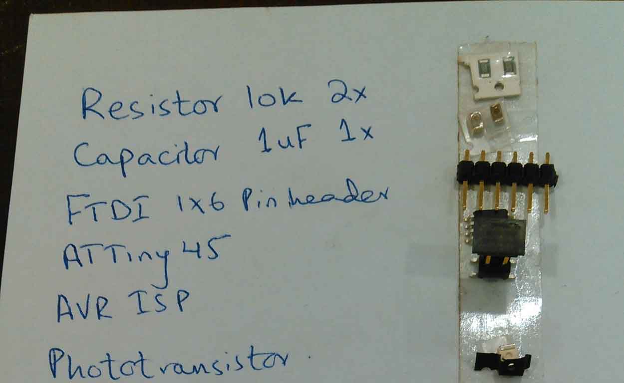
Component List
PCB Designing
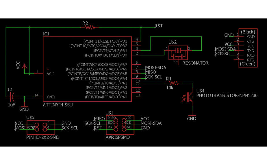
PCB Design and Schematic
Generating .RML Files
For generating RML files, first I need my PCB design in .png format for that I export my PCB design in .png while setting up 2000 dpi and Monochrome
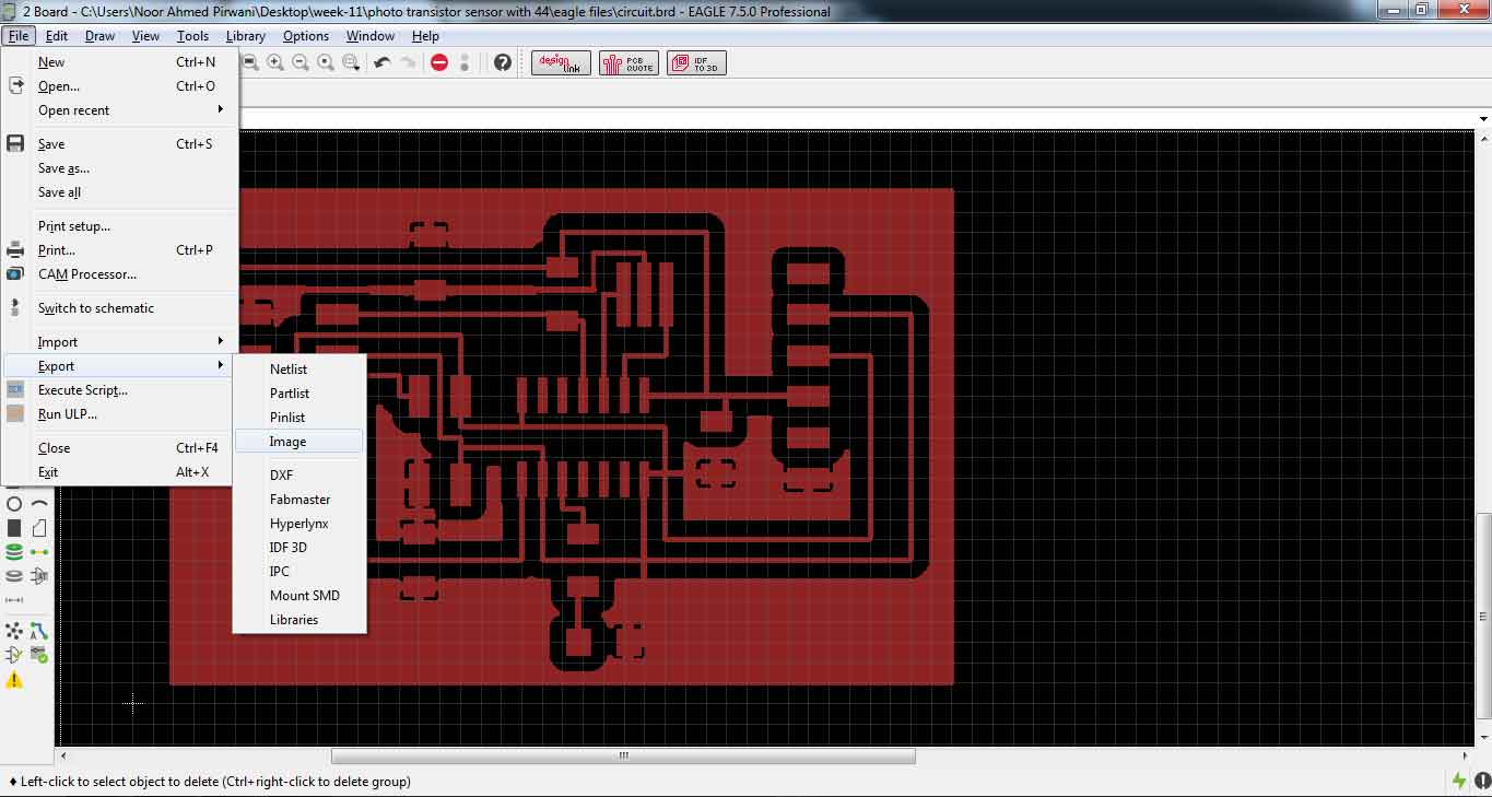
Exporting PCB design into .png format
.png is processed in Paint for making seperate files for traces and outline of a PCB design (in a case of drill holes in PCB one more file is made)
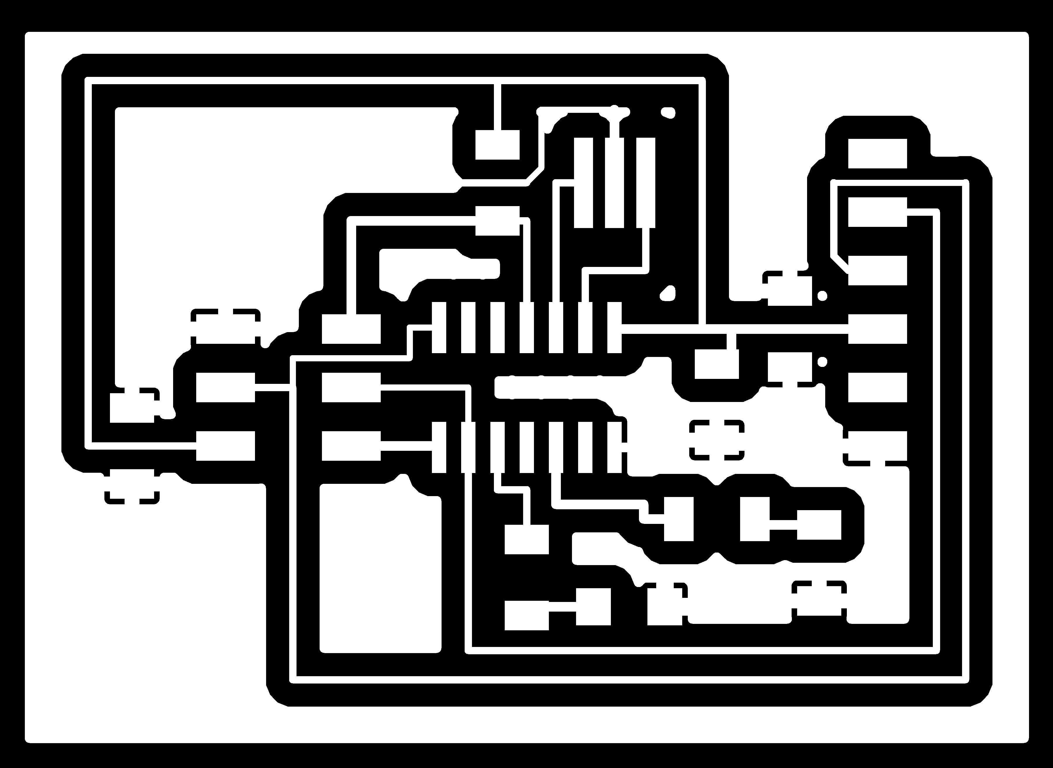
PCB traces

PCB Outline
after making traces and outline of a pcb I used fabmodules to generate RML files of both traces and outline.
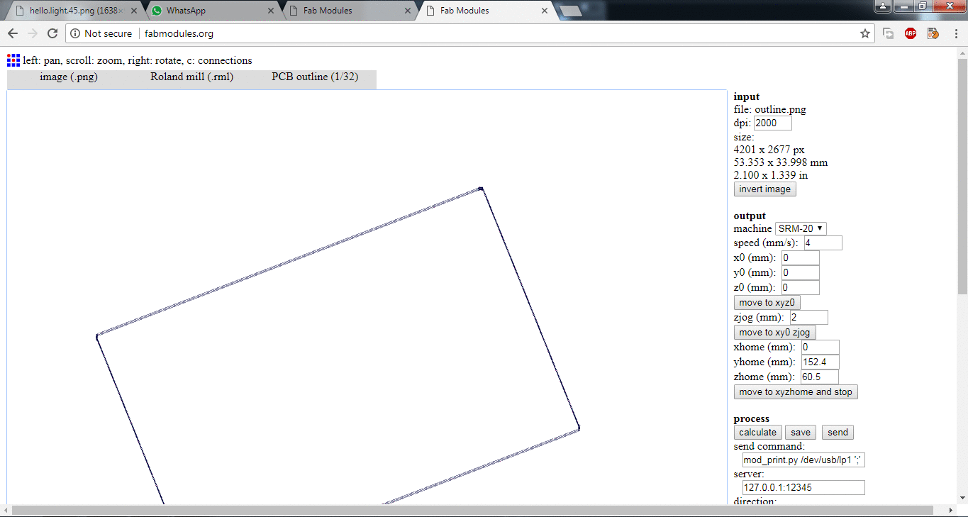
generating .rml file of PCB outline and PCB traces
Milling and Soldering
.rml files are given to Roland SRM-20 for milling, 1/32 drill bit is used for cutting outlines and 1/64 bit drill is used to make a trace on a board and here is the result.
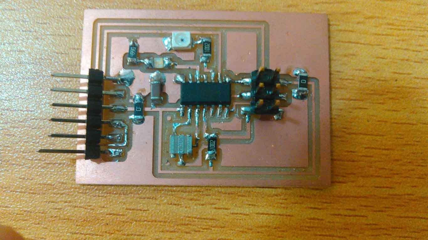
Circuit board with all the components soldered on it
Programming the board
I followed the same steps which I mentioned above while working on hello temperature board. But here a little bit change i C code which I mentioned in steps. I programmed my board by doing some changes in Neil's hello.light.45.c code and Neil's hello.light.45.py. Before programming the board first it is required to burn bootloader in it.
Burning bootloader using Arduino IDE
While compiling I got error in setting of VCC ref
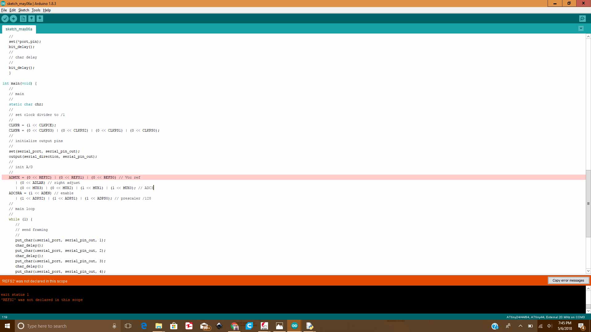
'REFS2' was not declared in this scope
Then I set the Vcc Ref by checking datasheet of ATtiny44.
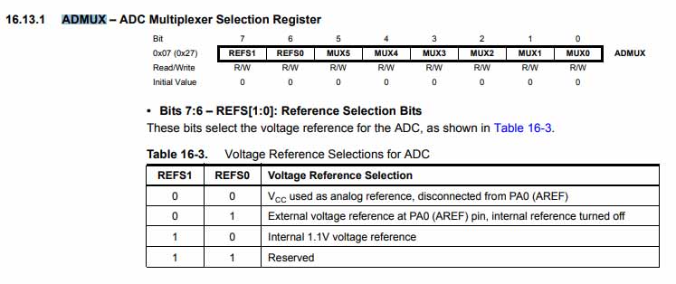
Vcc reference setting in datasheet of ATtiny44
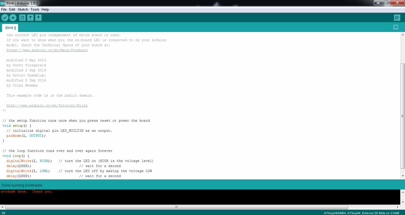
Then in next try code uploads successfully
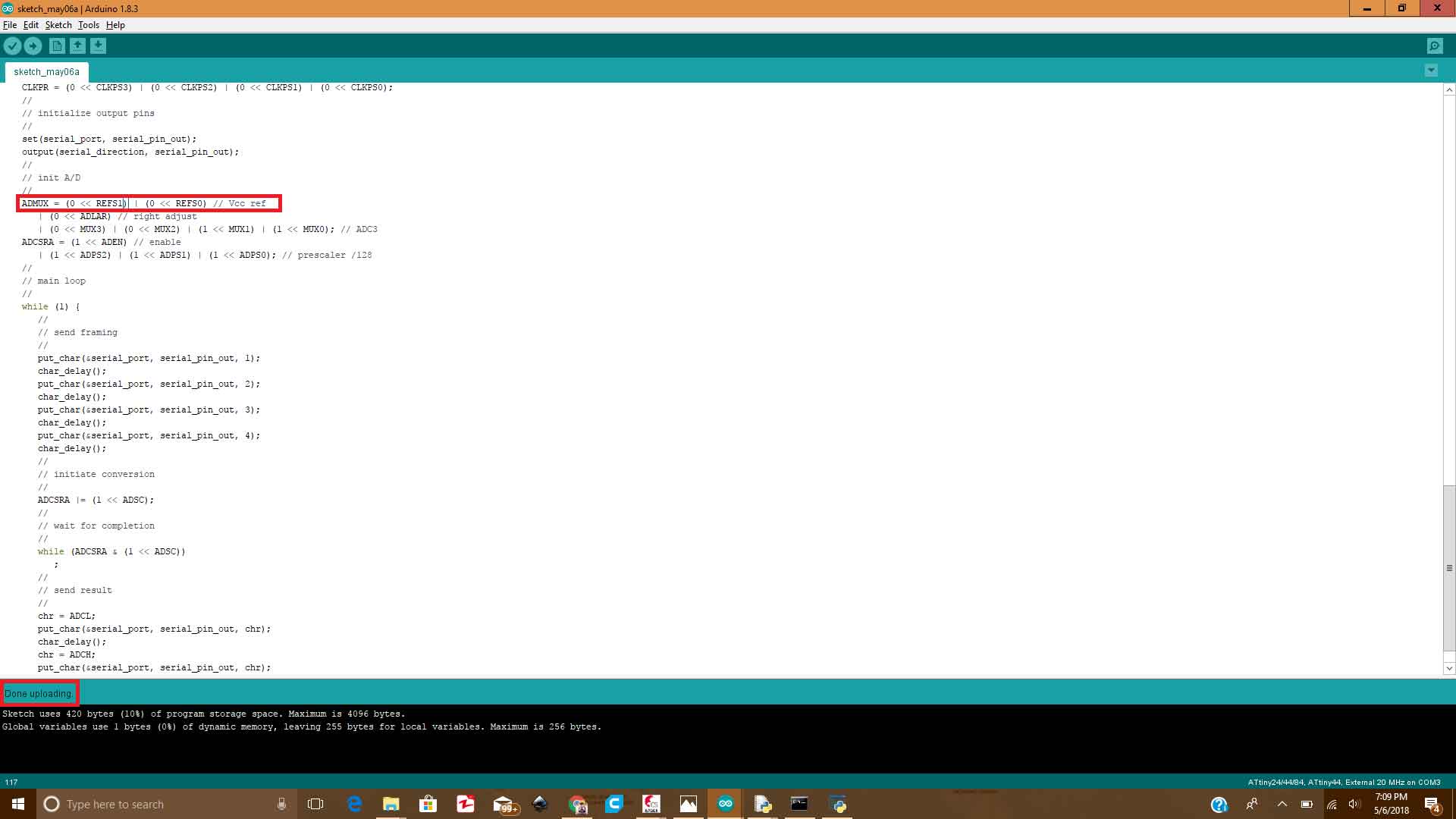
Upload Successful
To check the result on serial monitor I used same method which I mentioned above in temperature sensing cicuit about Python
Python IDLE Window
The bar to show light presence
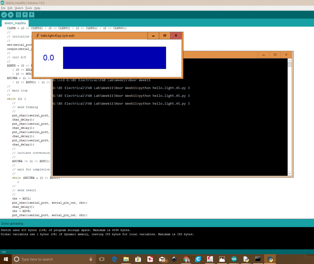
End Result
Group Assignment
In this week group assignment we have to measure analog levels and digital signals in an input devices.
Measuring Analog Levels of Phototransistor
SFH 320 Silicon NPN Phototransistor is used by one of our group member in individual task in which the circuit is detecting light and displays result of light intensity on bar using python. So as the group assignment we measured the resistance of this component which is changed when we increase or decrease the intensity of lights on it. The resistance is measured by Digital Multimeter. We observe that at one instance when we increase the intensity of light resistance decreases and when we decrease intensity of light resistance increases.
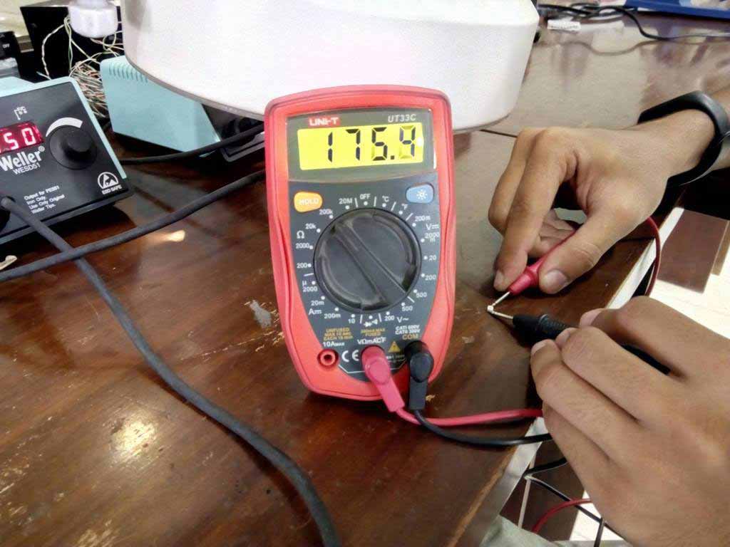
Measuring resistance with low intensity of light
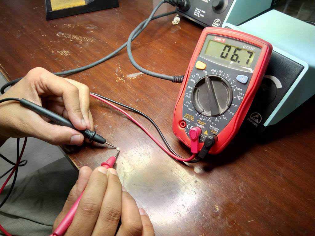
Measuring resistance with high intensity of light
Detecting Digital Signals in UltraSonic Sensor
HC SR-04 Ultrasonic sensor is used by one of our group member in his individual task of this week. We detect the change in digital signal in Oscilloscope using arduino UNO. A sensor is connected with arduino and the pin of Echo is connected with Oscilloscope. Arduino is program to detect obstacle in front of Ultrasonic sensor (a code is attached with files), when an obstacle is present in front of Ultrasonic sensor we found change in wave in oscilloscope
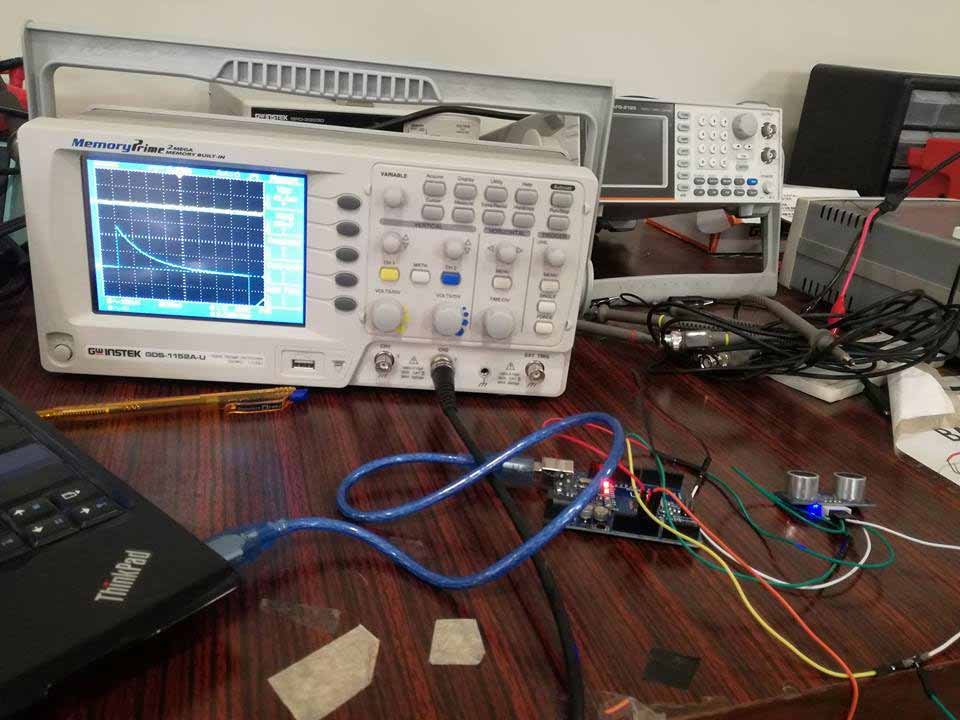
A digital signal without obstacle
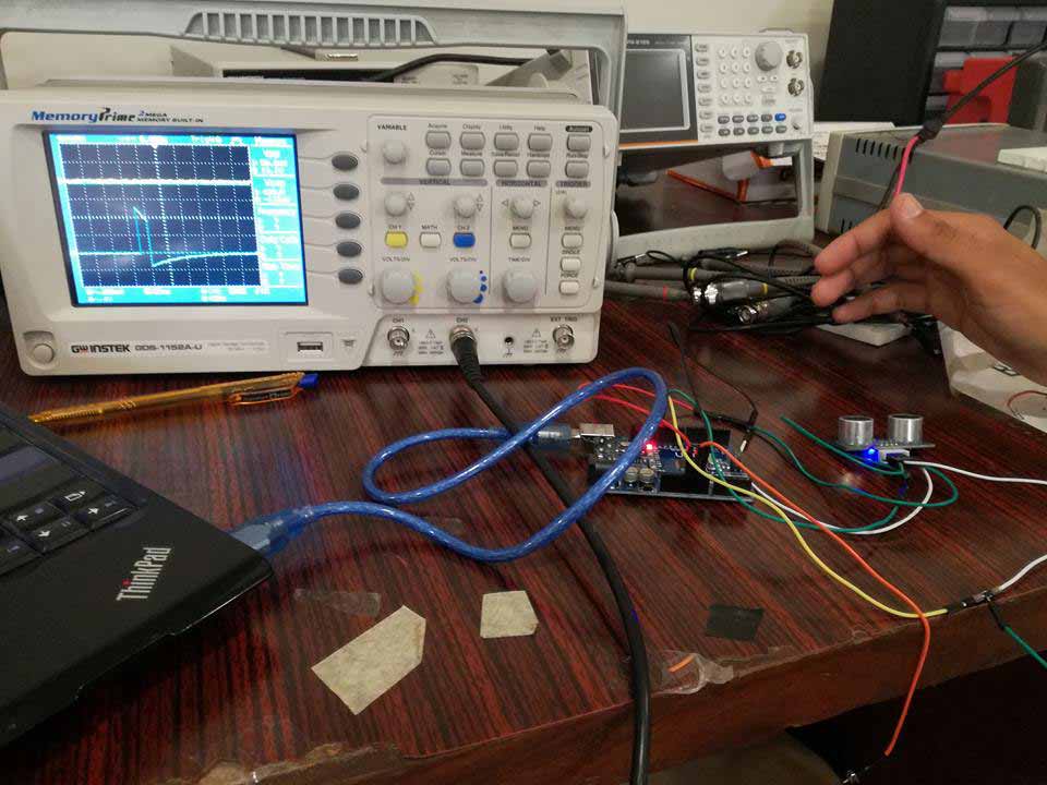
A digital signal with obstacle
"Click here"to download all files of this week

This work is licensed under a Creative Commons Attribution-NonCommercial 4.0 International License