
|
| Sukkur IBA University Merit, Quality, Excellence |
WEEK-12
Output Devices
Lecture & Recitaton of a Week:
Lecture on 11th of April, 2018: Output Devices by Neil Gershenfeld
Recitation on 16th of April, 2018: Making machines by Jens Dyvik, Nadya Peek, Jonathan Ward, Daniele Ingrassia
Tasks for a Week
- individual assignment: add an output device to a microcontroller board you've designed, and program it to do something
- group assignment: measure the power consumption of an output device
Individual Assignment
This week individual assignment encourages me to make/design my own board. The plan for this week is to make/design a board (which maybe further help in upcoming weeks aswell) and connect RGB strips with it, and program it with different effects of lights.
My Own Design
After redrawing so much controller boards in past weeks I planned in this week to make my own design, for this I want to make a board which is not only use in this week but kind of general purpose board for me, and for that I need more pins then ATtiny45 or ATtiny44 thats why I choose to work with ATMega328p which is 8-bit microcontroller with 32 pins A datasheet is downloaded from here .
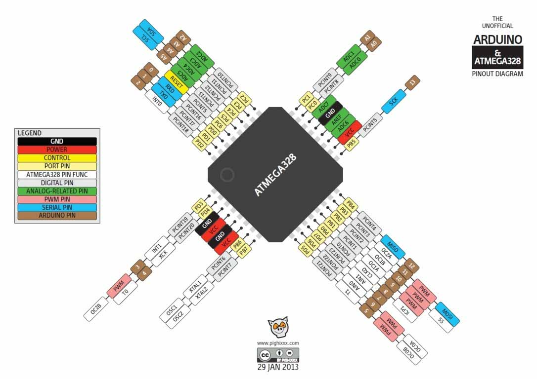
ATMega328p Pin Description
PCB Designing
For PCB designing I worked on Eagle 7.5 (an introduction of this software is mentioned in Electronic Design Week). First I made a schematic of board:
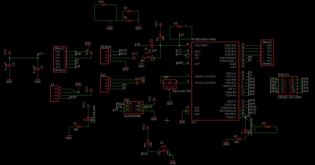
328p Board Schematic
then I generate PCB board and route it.
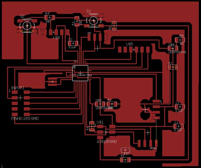
PCB Design
Generating .RML Files
For generating RML files, first I need my PCB design in .png format for that I export my PCB design in .png while setting up 2000 dpi and Monochrome
Exporting PCB design into .png format
.png is processed in Paint for making seperate files for traces and outline of a PCB design (in a case of drill holes in PCB one more file is made)
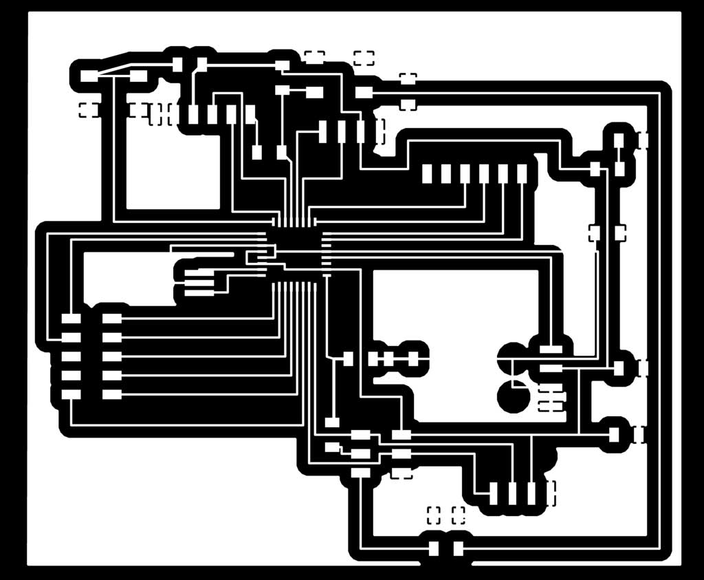
PCB traces

PCB Outline
after making traces and outline of a pcb I used fabmodules to generate RML files of both traces and outline, all important settings are mentioned in a pictures below, for detailed fabmodules settings visit Electronics Production Week
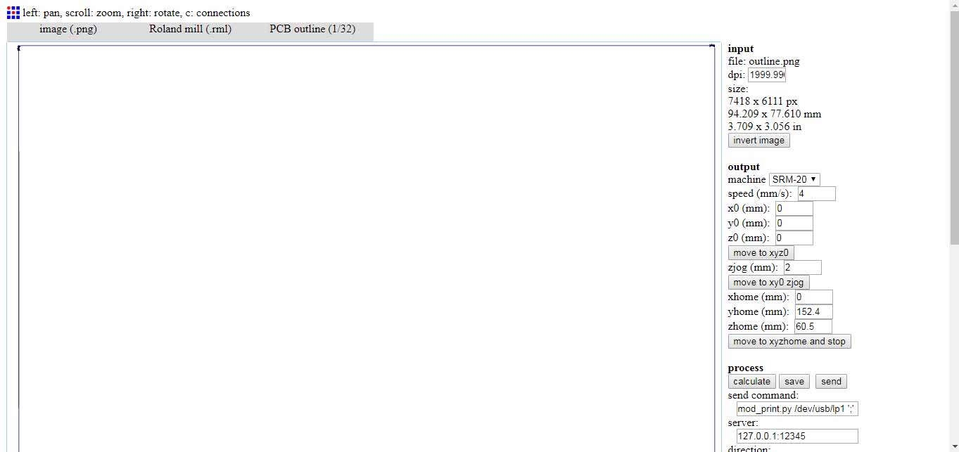
generating .rml file of PCB outline
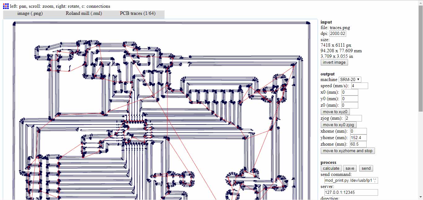
generating .rml file of PCB traces
Milling and Soldering
.rml files are given to Roland SRM-20 for milling, 1/32 drill bit is used for cutting outlines and 1/64 bit drill is used to make a trace on a board and here is the result.
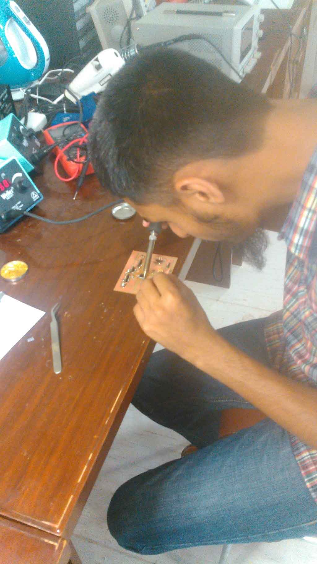
Soldering Components on a board
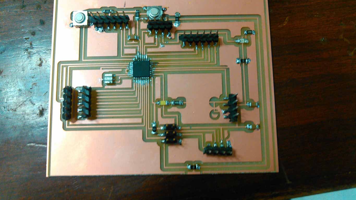
328p Circuit Board ready to Burn
328p Board Features:
- Support Programming from FTDI Cable
- One general purpose button connected with Pin2 of Arduino
- Dedicated I2C Connector
- Dedicated Serial Connector
- General Purpose 4 Analog Pins A0, A1, A2 and A3
- General Purpose 8 Digital Pins in which 5 pins are PWM~. Pin3~, 4, 5~, 6~, 7, 8, 9~, 10
- LED is connected with Pin13 to work with LED_BUILTIN codes
- Dedicated 2x3 ISP Pins
- Controller RESET button
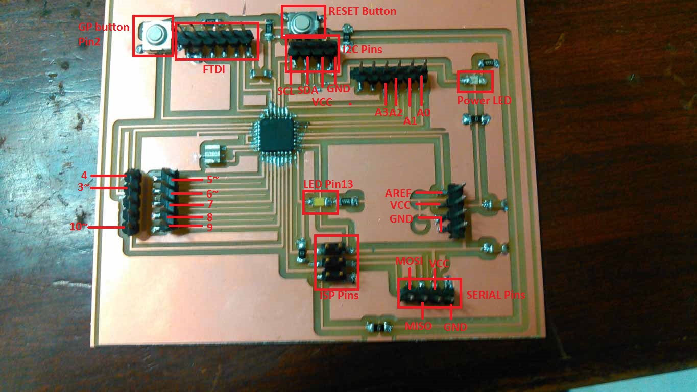
328p Board Pin Description
Programming the board
To program a board I need an ISP programmer, I made one developer board in Electronics Production Week so I used it with my temperature sensing board.
I am using Arduino IDE for programming my board. Before programming the board first it is required to burn bootloader in it. For setting up Arduino IDE to work with FabISP I mentioned in detail in Embedded Programming Week. The bootloader burn in board using FabISP which is 1 time process then after that I use FTDI Cable to program my board.
Below I shared some steps to burn bootloader in my board:
- Connect 328p board with FabISP and connect it with PC
- I found this core: MiniCore helpful to work with my 328p board. So first copy and past this link "https://mcudude.github.io/MiniCore/package_MCUdude_MiniCore_index.json" into File > Preferences > "Aditional Board Manager URLs"
- Now goto Tools > Boards > Board Manager... and install MiniCore by MCUdude
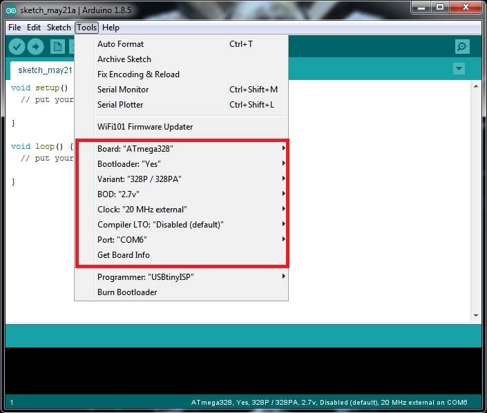
- These are the settings which I mentioned below before burning bootloader, set it up and click Burn Bootloader
After burning bootloader successfully now we test board with Blink Code which is present in Arduino examples, to check either it is working or not.
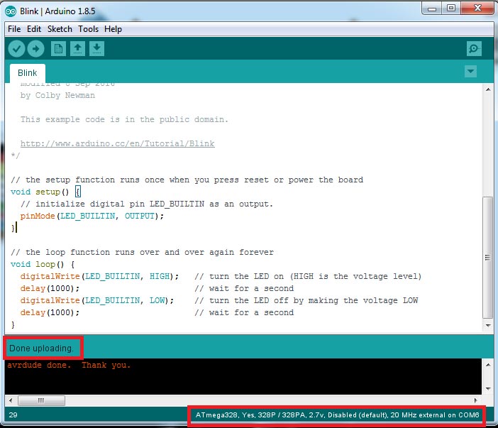
Blink Code Successfully upload in 328p Board
After Blink code successfully upload and run in 328p board now It is time to connect RGB strip WS2812B with board and program it to run differnet color effects
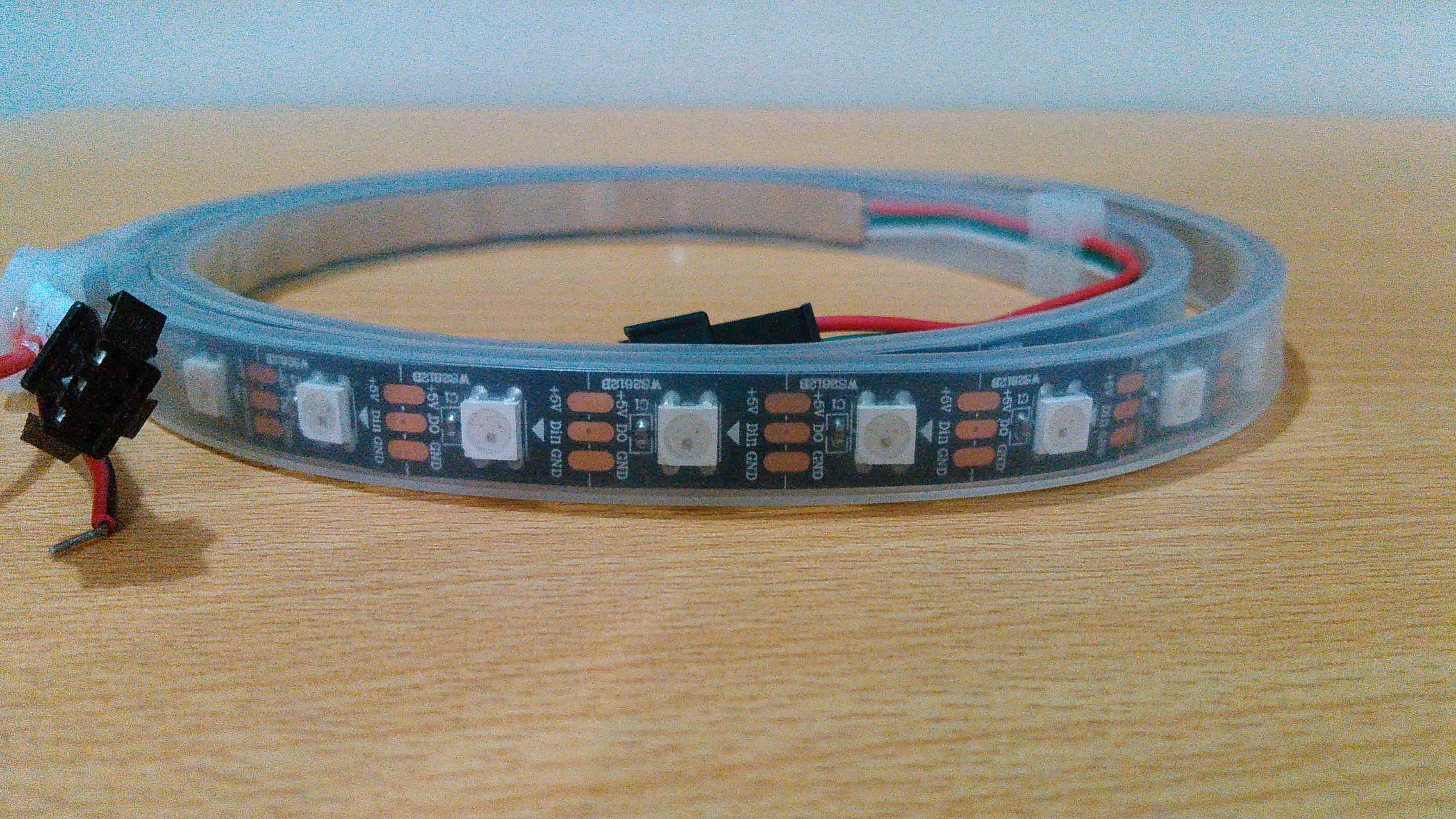
WS2812B RGB strip
Making Connections
Connect RBB strip address pin with Pin-6 of 328p board and connect supply pins VCC and Gnd with external source. I am using external source here because it is difficult for 328p board to draw this much current(current consumption of RGBs mentioned in Group Assignment)
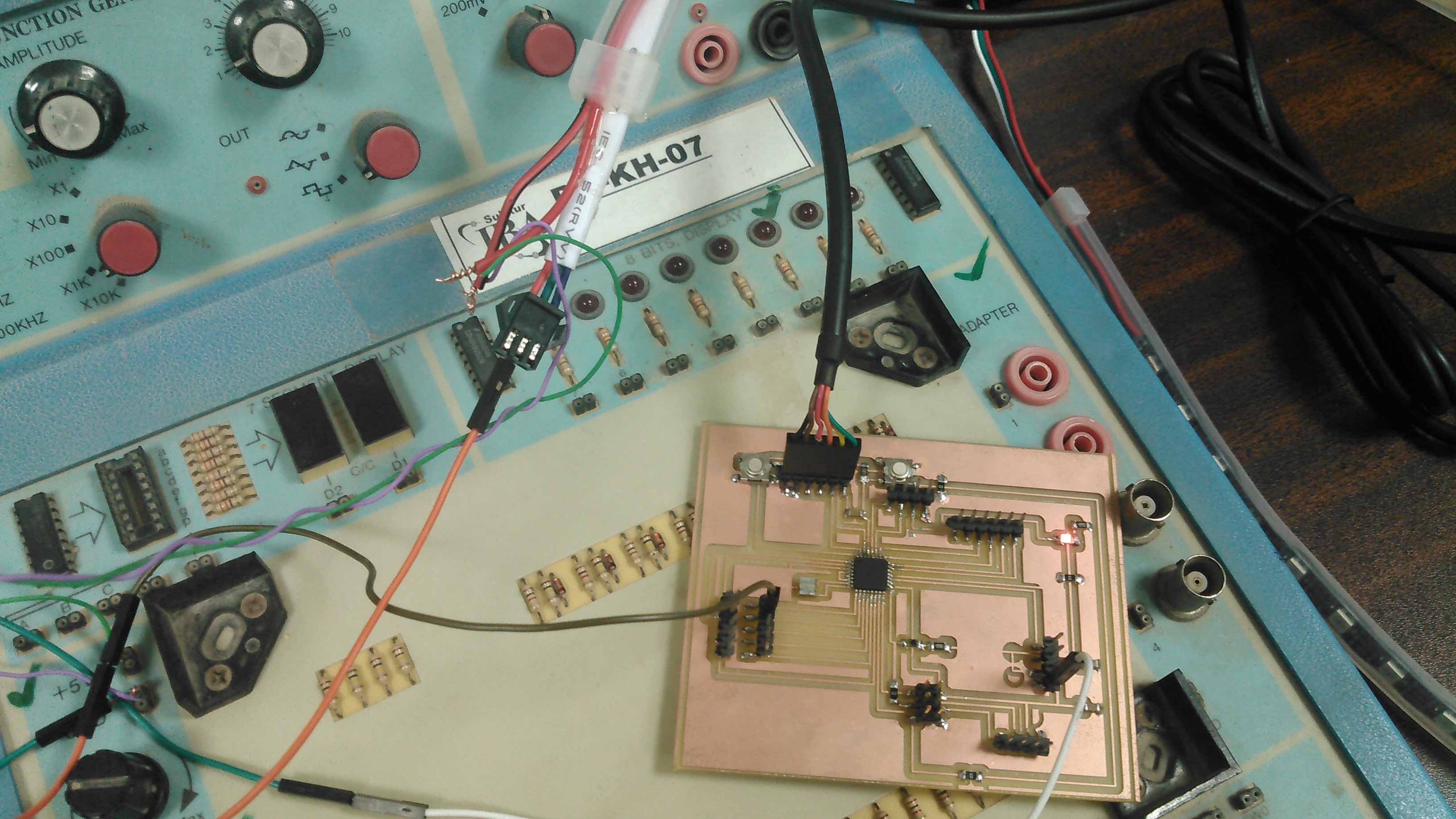
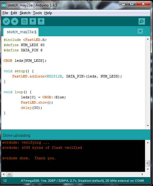
I found one code with different effects of lights from fastled patterns and upload it in my 328p board
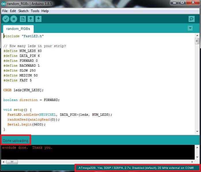
Random light pattern code uploaded in 328p board
The code is working perfectly and the results are as per imagine love to see floating colors all over strips
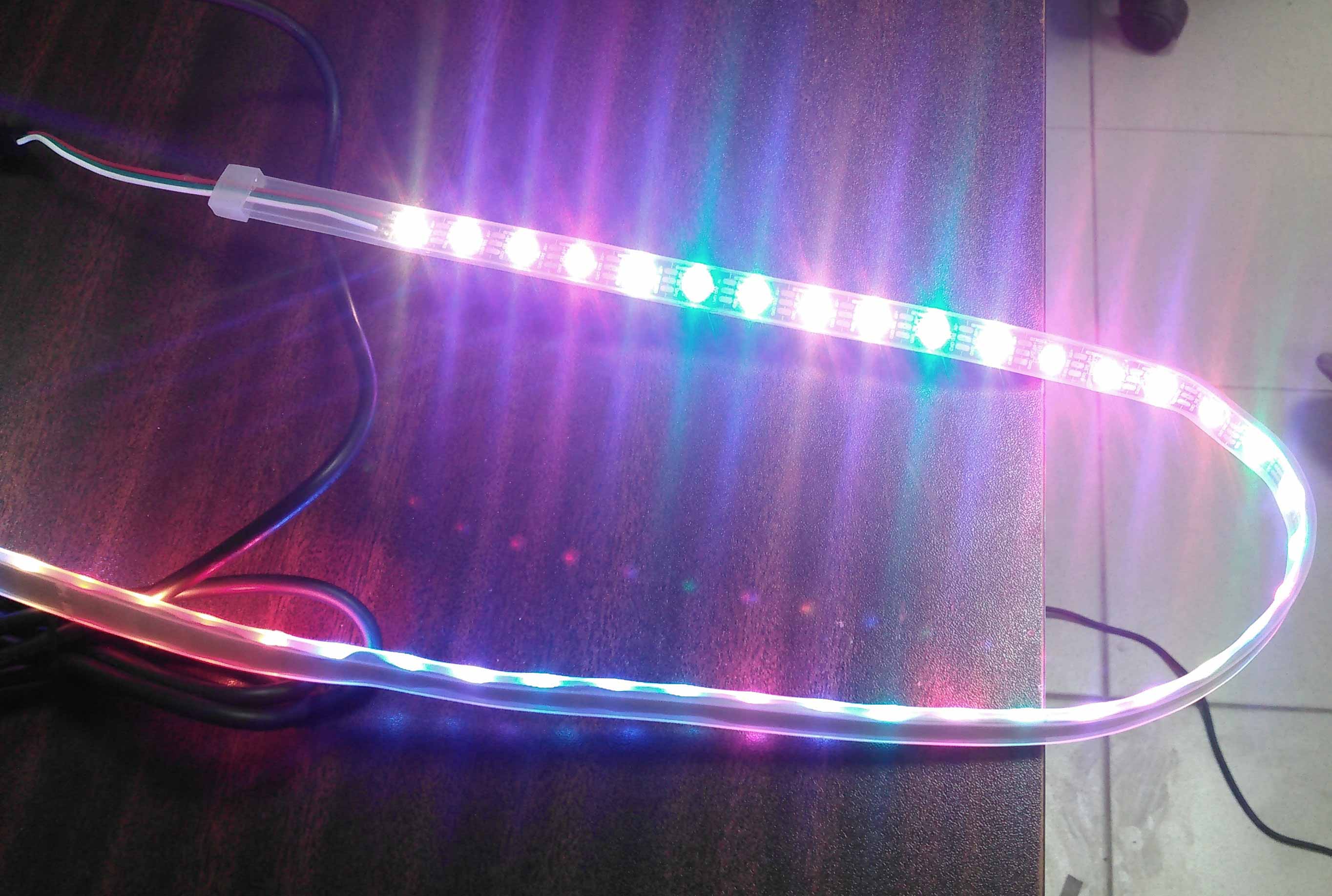
Fantastic final result of Output device week
Group Assignment
In this week group assignment we have to measure power consumptions of an output device.
Measuring Power Consumption of RGB LEDs
As one of our project is on RGB LEDs so we decide to find the power consumption of RGBs on different color pattern
We write some codes which blink 1 RGB with specific color and measure current on that project
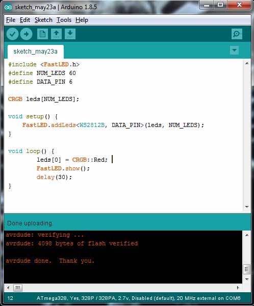
Code to check Red LED
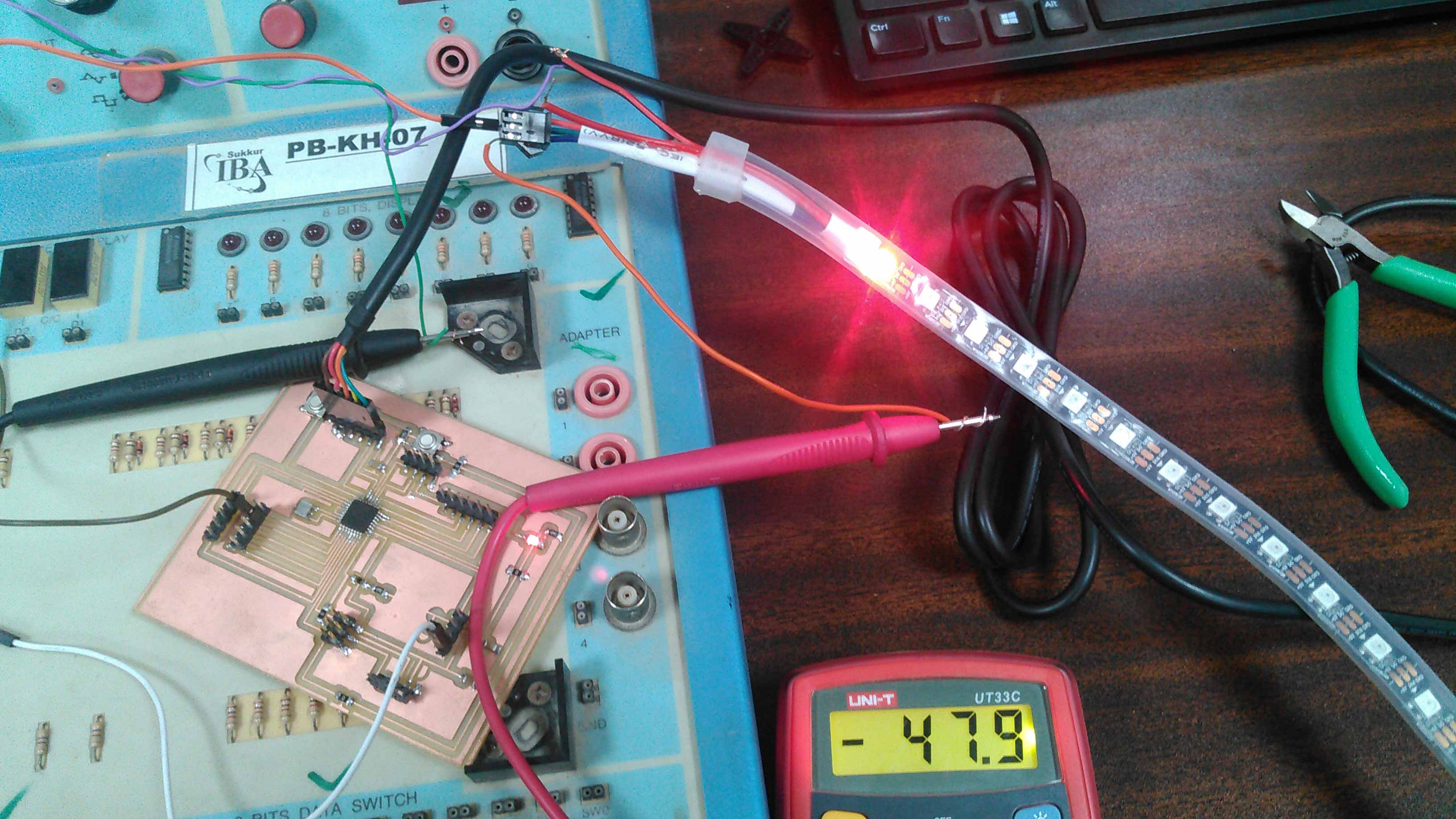
Checking current of RGB when 1 RED is on
The current is measured 47mA which is multiplied with 5 Volts is equal to 235mW

Code to check Green LED
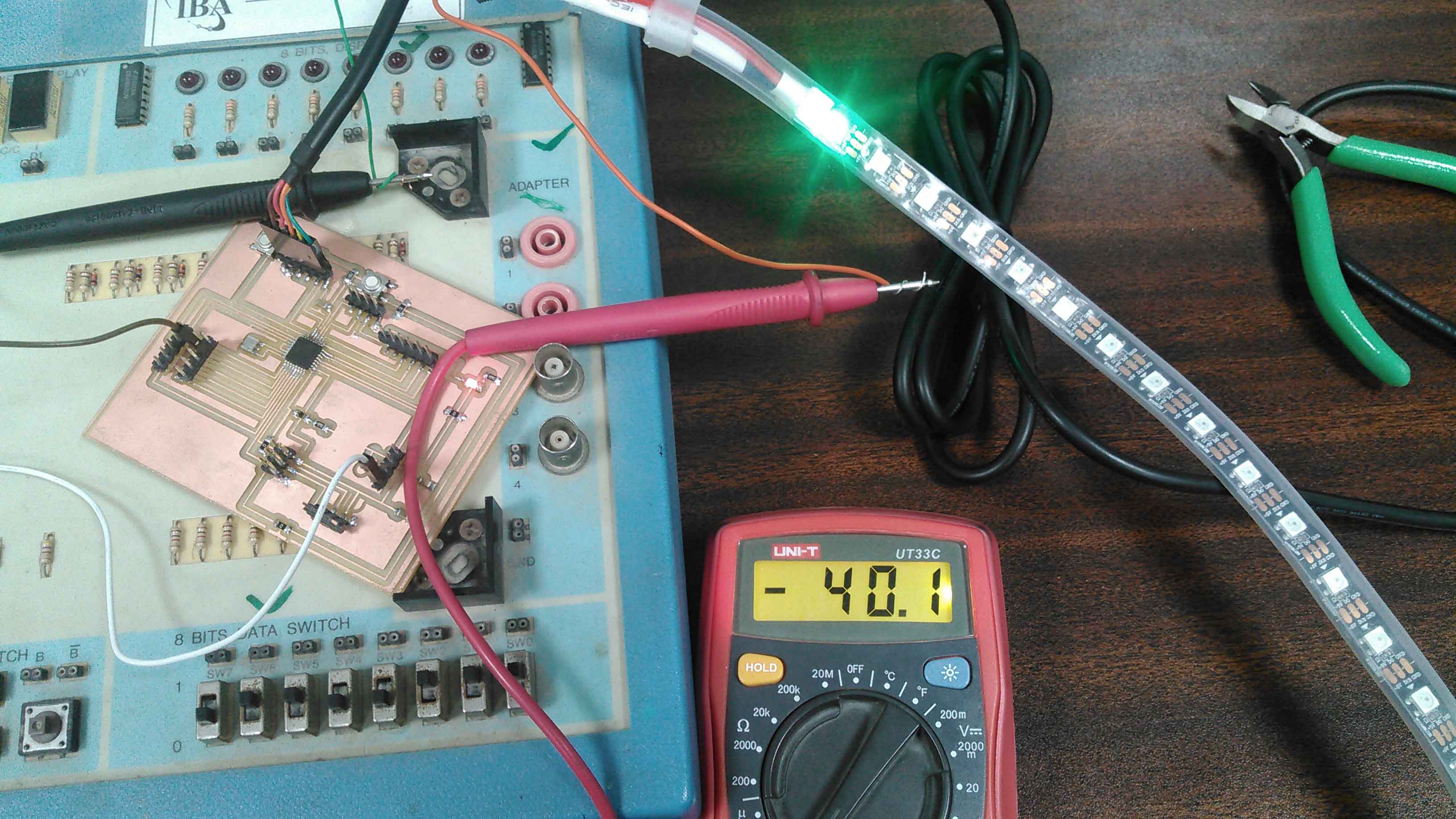
Checking current of RGB when 1 Green is on
The current is measured 40mA which is multiplied with 5 Volts is equal to 200mW
Code to check Blue LED
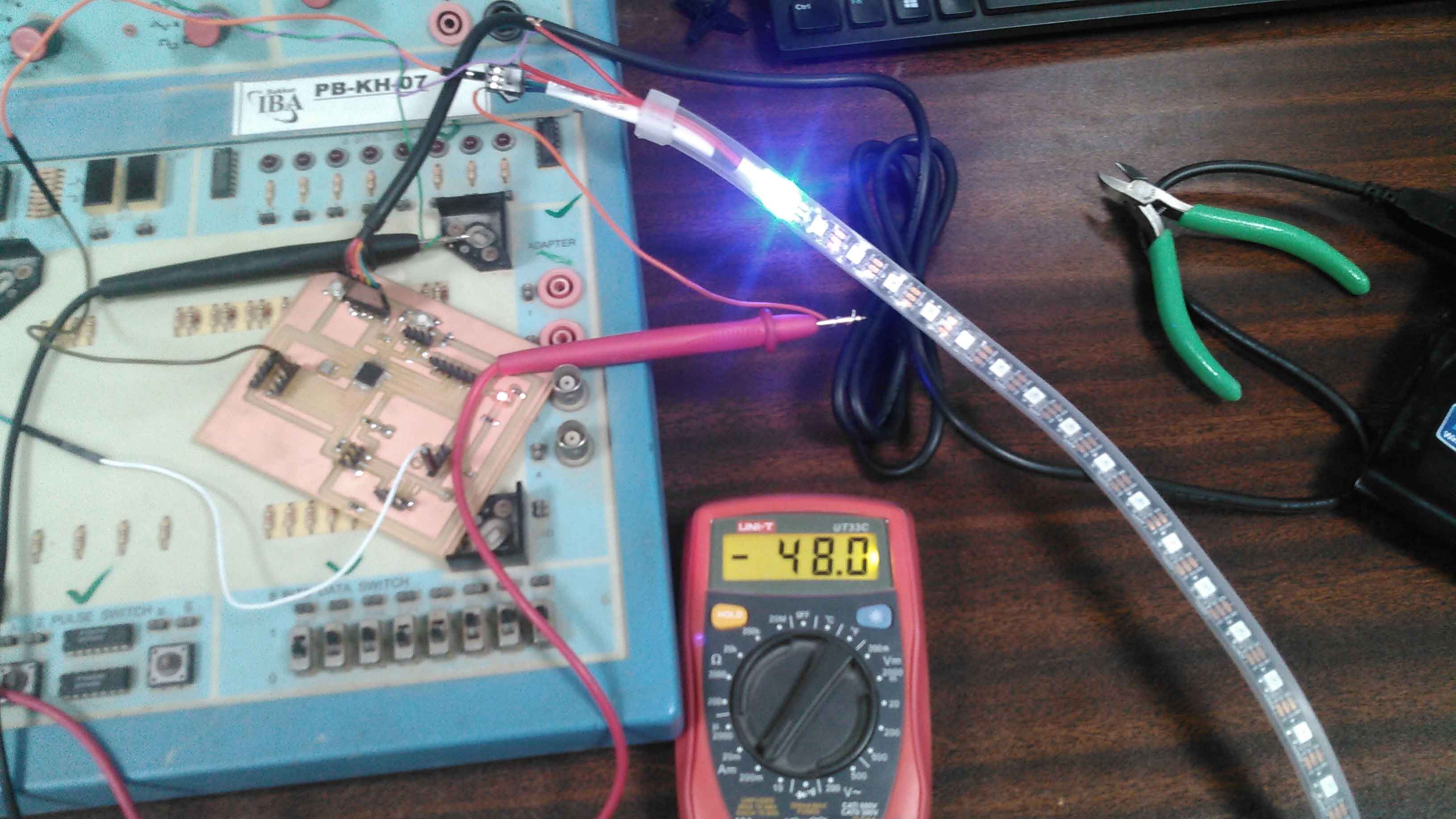
Checking current of RGB when 1 Blue is on
The current is measured 48mA which is multiplied with 5 Volts is equal to 240mW

Code to check White LED
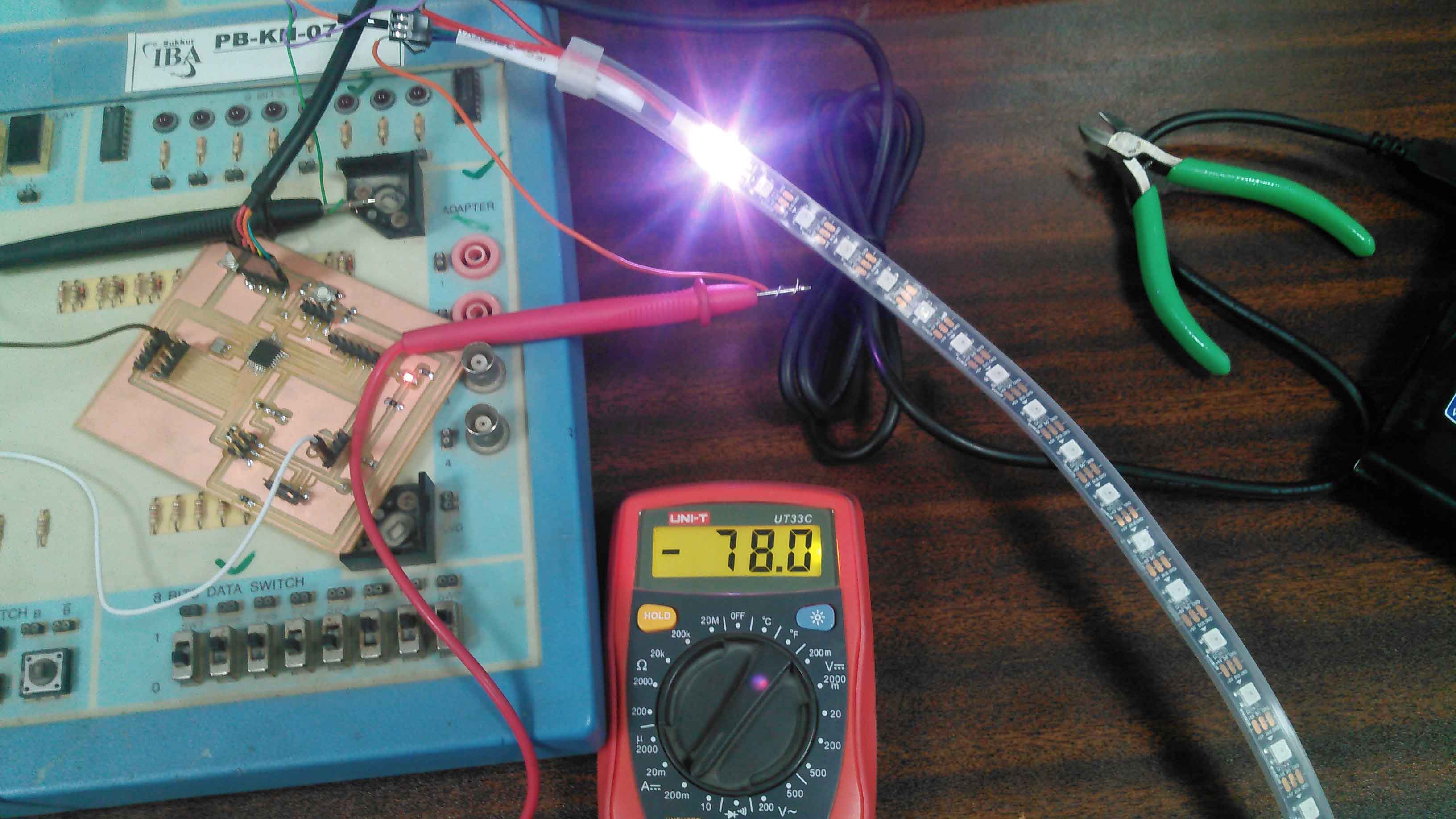
Checking current of RGB when 1 White is on
The current is measured 78mA which is multiplied with 5 Volts is equal to 390mW
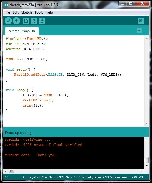
Code to check Black (no LED) LED
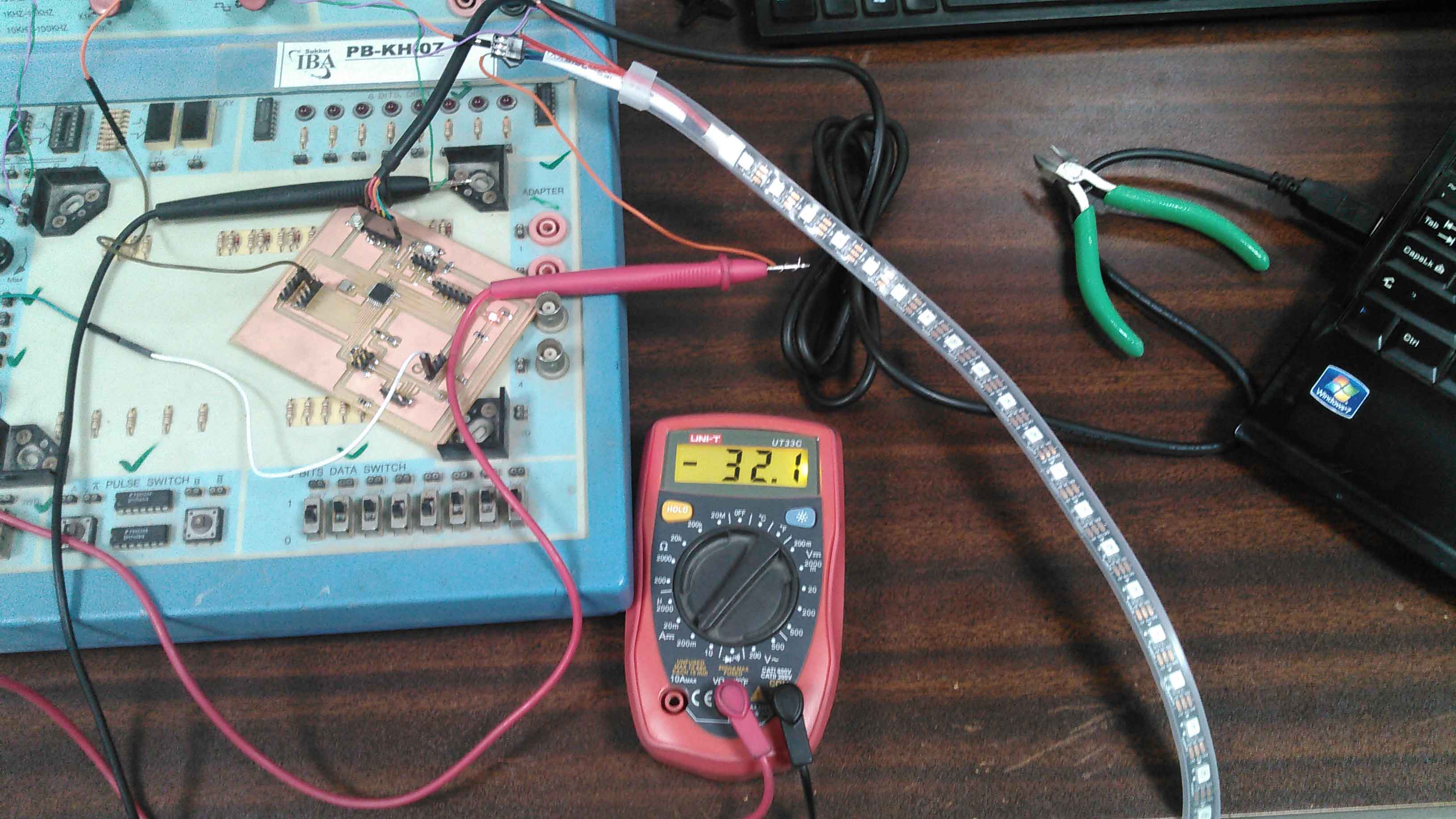
Checking current of RGB strip when no RGB is glow
The current is measured 32.1mA which is multiplied with 5 Volts is equal to 160.5mW
Different colors have different current consumptions. As per results we found that green color have low power consumption and white has maximum power consumption.
"Click here"to download all files of this week

This work is licensed under a Creative Commons Attribution-NonCommercial 4.0 International License