
|
| Sukkur IBA University Merit, Quality, Excellence |
WEEK-15
Mechanical Design
Lecture & Recitaton of a Week:
Lecture on 2nd of May, 2018: Mechanical Design by Neil Gershenfeld
Recitation on 7th of May, 2018: Mods by Neil Gershenfeld
Tasks for a Week
- group assignment: - design a machine that includes mechanism+actuation+automation - build the mechanical parts and operate it manually - document the group project and your individual contribution
Robotic Arm with 7 Servos
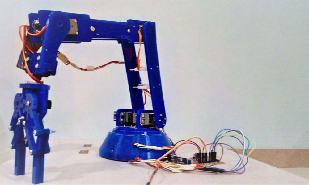
Robotic arm with 7 Servos
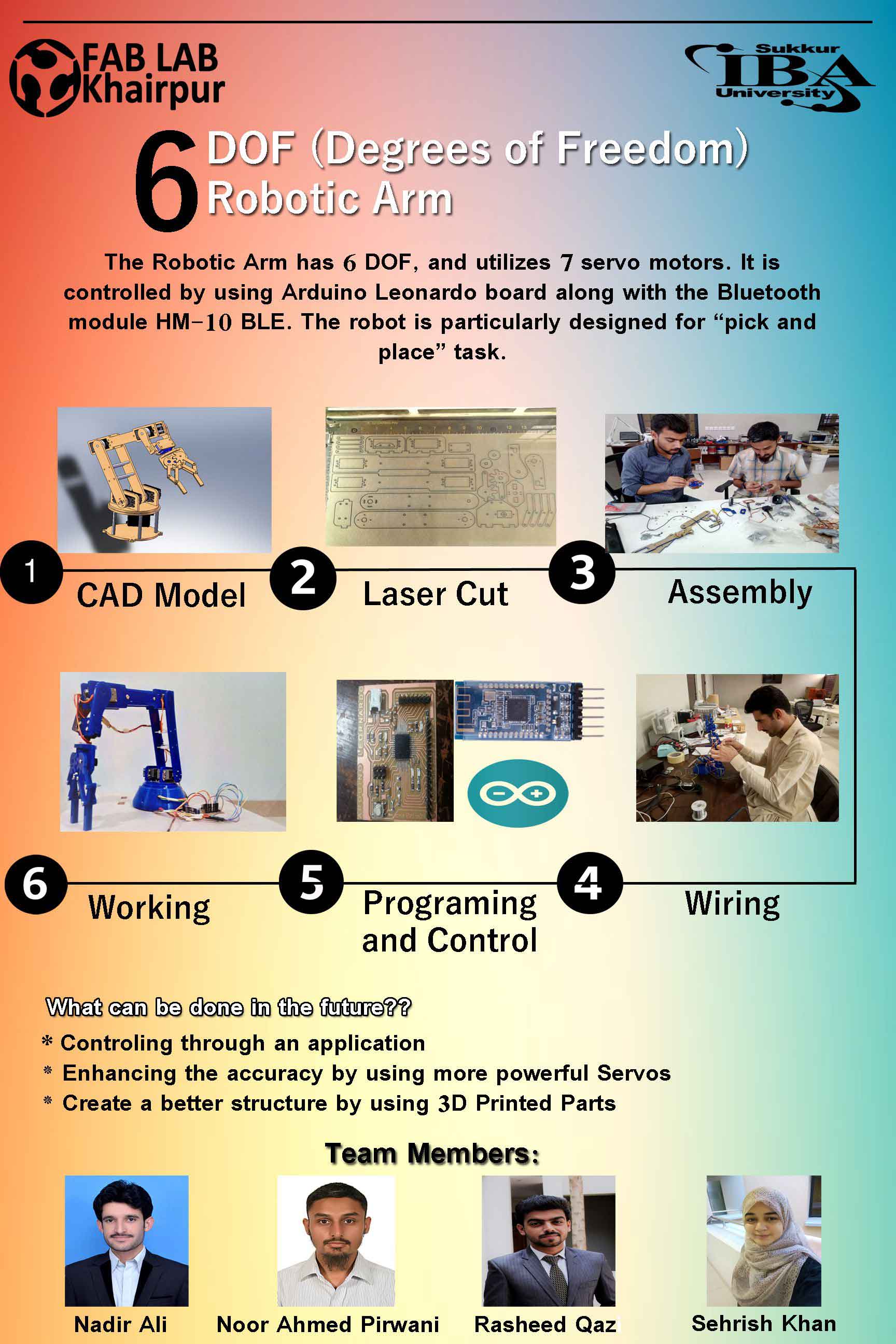
Poster Describing the Workflow of the Assignment
In this week and the upcoming week, we have to make a Machine. So, first we need to design the mechanical parts of our machine in this week.It is basically a group assignment, and every person is required to do a part of assignment and document their contribution.
Introduction:
In all essential aspects a robotic arm resembles perfectly the human arm in appearance,structure and in many of its functions.A human arm can move freely in 7 axis, but now a days it's not a big deal to see robotic arms which have the same degrees of freedom. A typical robotic arm is made up of seven metal segments, joined by six joints. The computer controls the robot by rotating individual step motors connected to each joint (some larger arms use hydraulics or pneumatics) Your arm's job is to move your hand from place to place. Similarly, the robotic arm's job is to move an end effector from place to place. Designed and realized in the project, the robot arm has the ability to move in 5 axis directions with 7 servo motors.
Benefits of Robotic Arm
- Robotic arms are fast and perform the pick and place tasks accuratel
- Robotic arms save the human labor time, and reduces the risk of injuries associated with tasks like replaceing,moving,picking and placing etc.
- Depending on the desired tasks that you want to do from your robotic arm, the accuracy can be increased.
- Robot arms work in agriculture, aviation, postal services, recording studios, and a thousand other applications
- Robotic arms render ease of use, better range of mobility, and re-programmability to increase the accuracy of tasks.
Axes of Robotic Arm
The Robotic arm moves in three axes:
- X-axis defines horizontal motion.
- Y-axis defines vertical motion.
- Z-axis defines depth motion.
The working of the robotic arm in each individual axes can be understood in a better manner by resembling and anlaysing the movement of a human arm.Each axes charecterize a space through which the robotic arm moves.If we associate the use of axes as a pivot point , then each pivot point is responsible for motion of the robotic arm for a range of motion in the same manner as our wrist and elbow. Increasing the number of axes or pivots , increases the overall range of motion. Here, we will be using 5-axes motion and for that we need 7 servo motors.
Different Parts of a Robotic Arm:
- Controller
- Manipulator
- Gripper or end effector
- Power supply or energy source, and
- Data acquisition system (vision sensors system).
- Programming
Task Division:
The whole project comprises of the following parts and divided in our Group. It's really an interesting and challenging task to do.
- CAD Design of the Robotic arm, Laser cut and 3D print the parts. (This Task has been Assigned to Mr. Noor Ahmed Raza Pirwani Me )
- Assembling the parts to make the Robotic arm (This task has been assigned to Ms. Sehrish Khan, Rasheed Qazi)
- Electronics Production , designing the Controller (This task has been assigned to Mr. Nadir Ali)
- Programming of the Controller(This task has been assigned to Noor Ahmed Pirwani Me and Rasheed Qazi)
Designing and Scaling:
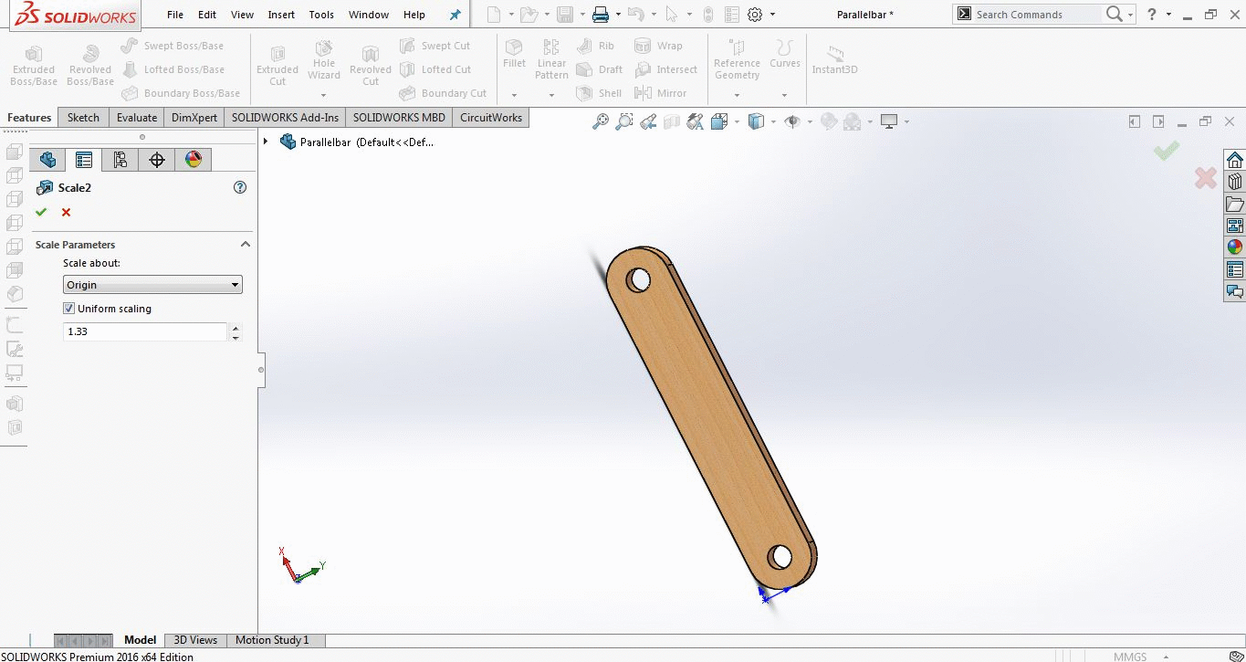
I start 3D modeling in FabAcedemy and have no experince before that but after group meetings and discussion about task division my team decided to gave me 3D modeling part (they think I am good in it but they actually gave me one more opprtunity to learn). The challenge of 3D Modeling was different this time I don't have to make from scratch but have to scale the design which we found robot from here. The design is based on 7 servos wit 6 Degree of Freedom the challenge is to scale it to 1.33 times then actual size by maintaining the size of motor, screw holes and other internal shapes constant.
The link (mentioned above) have part files which is accessible in SolidWorks. So I opened parts of robotic hand one by one and increase there sizes
Challenges faced while Scaling:
While scaling the Design, there were some limitations which were to be kept in mind. These are discussed below:
- As we are working in Solidworks, so we need to change the model part by part. Increasing the whole part size to 1/3 led to an increase in the dimension of screw holes and the other internal shapes like motor placement, holes to fix motor shaft etc.
- We already designed and 3D print the base with respect to original size of robotic arm. Now to 3d print it again by scaling it is waste of material, so we were limited to keep the scale ratio of 1/3.
- The increasing in scale is also bounded to 1/3rd because an increase in the size any further will make the robotic arm unable to handle the weight factor desired for the design.
- The size can be increased further if we manage to arrange high torque motors and make whole part again (with base part).
Resolving the issues of Scaling:
After analysing the design and hardware constraints, the following steps were taken to resolve the scaling issues: Instead of increasing the scaling factor of the whole part, first the internal parts designated for screws and size of other internal parts were decreased by dividing them with 1.33. After decreasing the internal parts by 1/3 , we increased the whole part to 1/3rd so that it can make screw holes, motor placement, shaft placement and other internal parts to there actual size.
The scaling process is illustrated by the pictures below:
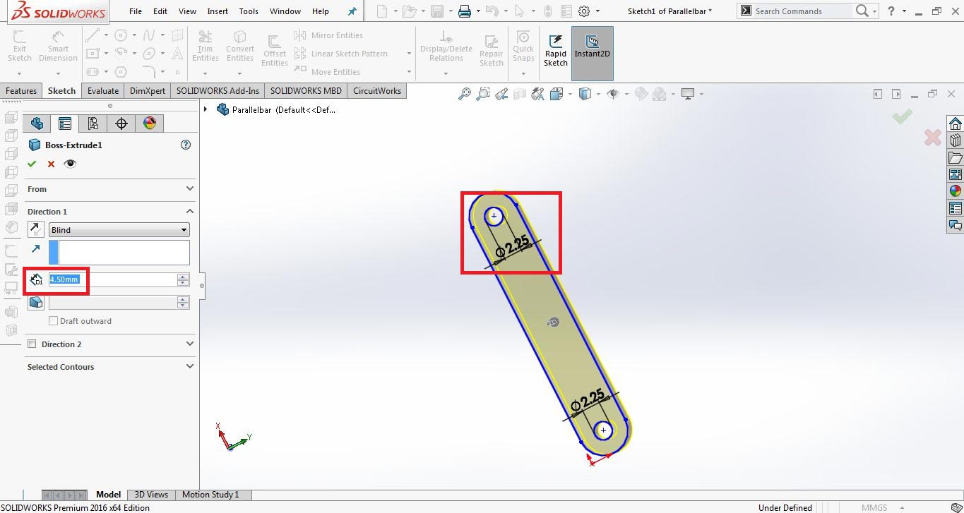
set dimensions of thickness and screw holes to the value which is multiplied by 1.33 to become desired values
scaled the parameters with 1.33 to make screw hole 3mm (again), made thickness 6mm (which is required) and scale the hole part to 1.33x
There are other tools of solidworks used also while scaling like ; center line to check the boxes are alligned, mate tool for assembling the parts etc. Finally, the whole model was scaled up by the scale factor of 1/3, keeping the scale ratio constant.
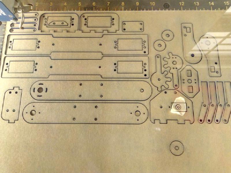
LASER cutting of parts:
After scaling of all the parts in Solidworks, the parts were joined together and made an Assembly by creating the Mates as shown in the pictures above.The next step was to cut all the individual parts on Laser cut.Follwing are the necessary details of Laser cut of the parts.
- The .DXF files were imported in Inkscape to make a pdf file.
- It was make sure that no space was left unused , so we try our best in setting to less utilize the material
Laser cutted parts are the perfect example from idea to reality
The next part of process is to assembling the robotic hand so I pass the laser cutted parts and explain the changes in 3D model with my team amtes so they continue to assemble robot

Explaining team about changes in robotic hand for Assembling Process
"Click here"to download all files of this week
"Click here"to visit the complete documentations of mechanical design and machine design weeks

This work is licensed under a Creative Commons Attribution-NonCommercial 4.0 International License