
|
| Sukkur IBA University Merit, Quality, Excellence |
WEEK-5
Electronics Production
Lecture & Recitaton of a Week:
Lecture on 14th of February, 2018: Electronics production by Neil Gershenfeld
Recitation on 19th of February, 2018: Functional representations by Matt Keeter
Tasks for a Week
- group assignment: characterize the specifications of your PCB production process
- individual assignment: make an in-circuit programmer by milling the PCB, then optionally trying other processes
Group Assignment
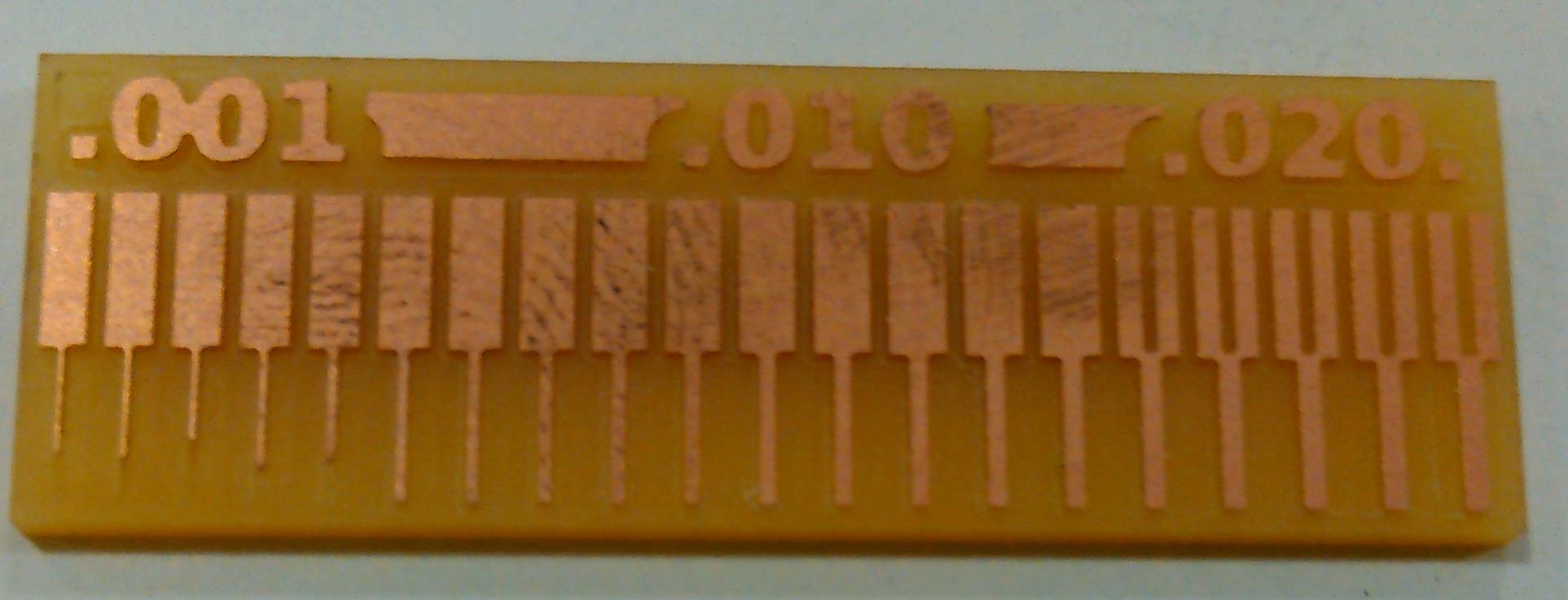
For group assignment, we have to characterize the specifications of PCB production process and for that we are using Roland monoFAB SRM-20 Milling machine. For learning process in both group and individul assignments we are using basic PCB Board which is FR-1. We are fabricating a Traces-width board, which has a traces which is very near in different sizes. For cutting and traces we are using 1/32 and 1/64 drill bit respectively.
Fabricating PCB
We are using these png files for trace and outline
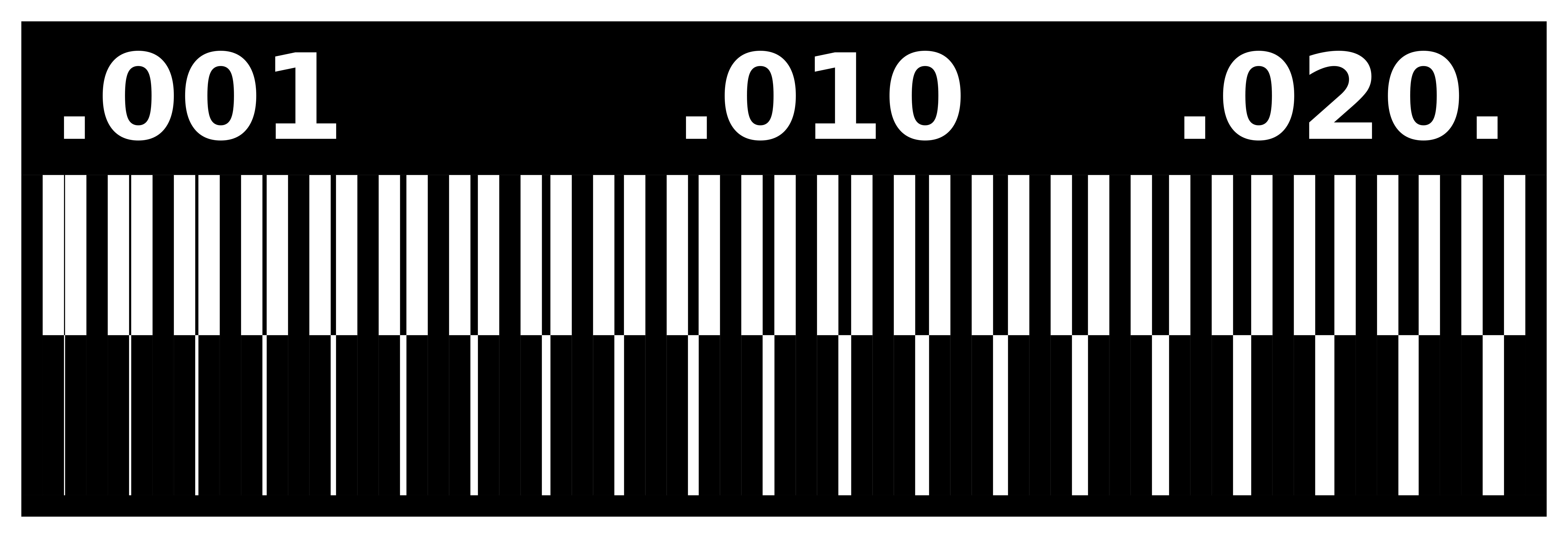
traces file using 1/64 drill bit to trace

outline file using 1/32 drill bit to cut
Steps for generating RML
- In the program tab, click on open server program
- Click on PCB under SRM-20
- Click on image(.png) as your input format file
- Browse and open your desired png file
- After opening your file, select mill traces 1/64
- Go to the modules tab and click on add server module
- Click on save
- A pop-up will appear as shown below, drag this file and connect it to the output node of Rolland SRM-20 milling machine
- Click on "Calculate" and the file will automatically be saved
- Your RML file is ready
- To check the traces and path of PCB , click on view
- Select the png format of outline and click on mill traces 1/32 and click calculate to save this file.
Generating RML files
After generating RML we send both files to ROLAND monoFAB SM-20 Machine. following steps below to show how machine works
- Place PCB on board
- Open VPanel for SRM-20 in Desktop
- Change the drill bit
- Select origin to x/y and z axis by changing values of x, y and z axis from where it should be start.
- Adjust drill bit until it touches PCB board
- Change Z-Axis value little bit to dig PCB board slightly, then set new value of Z-Axis as origin.
- click on "Cut" and locate .rml file which we want to use
- click on "Output" to start the process
PCB Fabrication uisng Roland monoFAB SRM-20 Machine
The outerline file of a PCB need to fix, it did not complete the path. To fix this boundary using Photoshop we are making one more file of outline boundary with same pixel/inch size with respect to traces file.
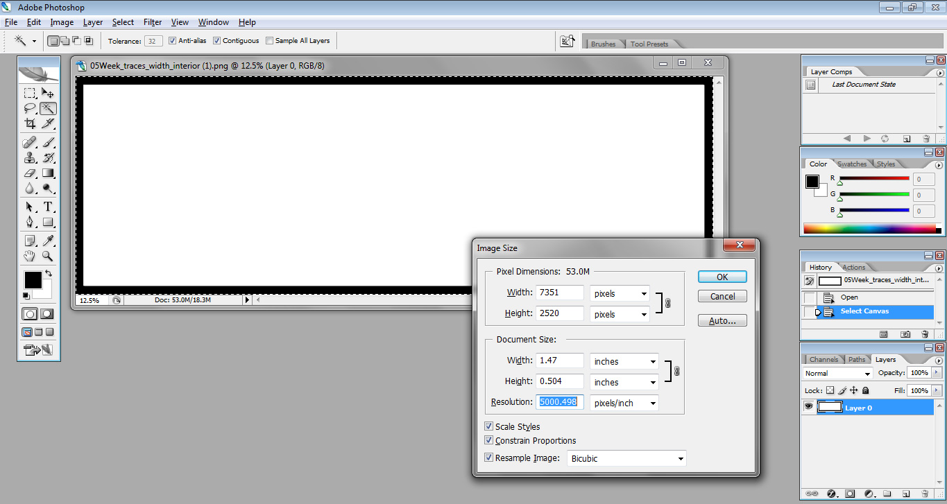
setting up pixels and inch size of file using adobe photoshop
Then we generate the .rml file using above method.
End Result
The group assignment shows that how much machine works precisely with 1/64 drill bit to show even 0.001mm line
Individual Assignment
The task for this week is make an in-circuit programmer by milling the PCB. I break this task into two main parts
- Making and Soldering board
- Uploading Program in the board
Making a Development Board
I download development board file from our week 5 lecture
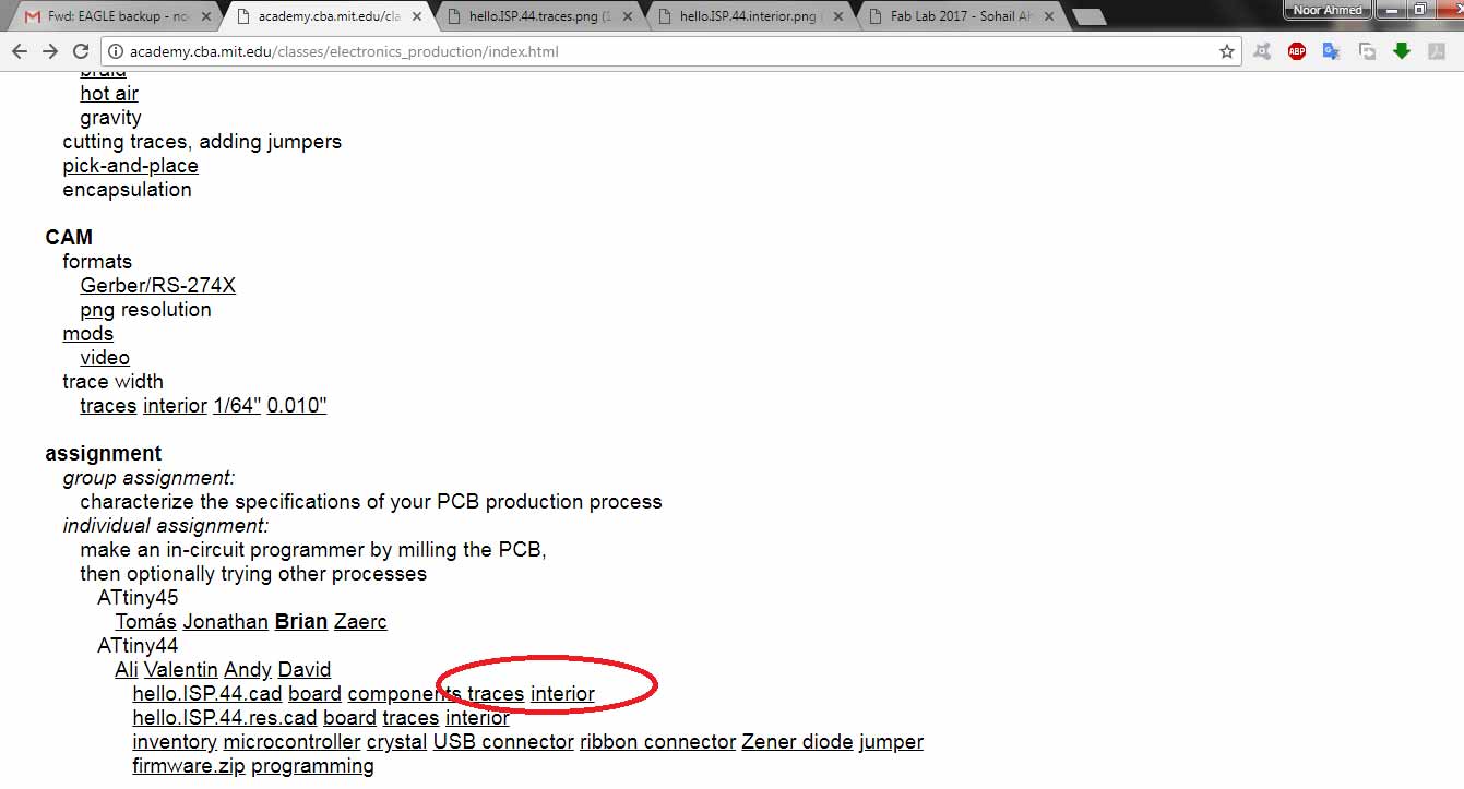
File in red circle
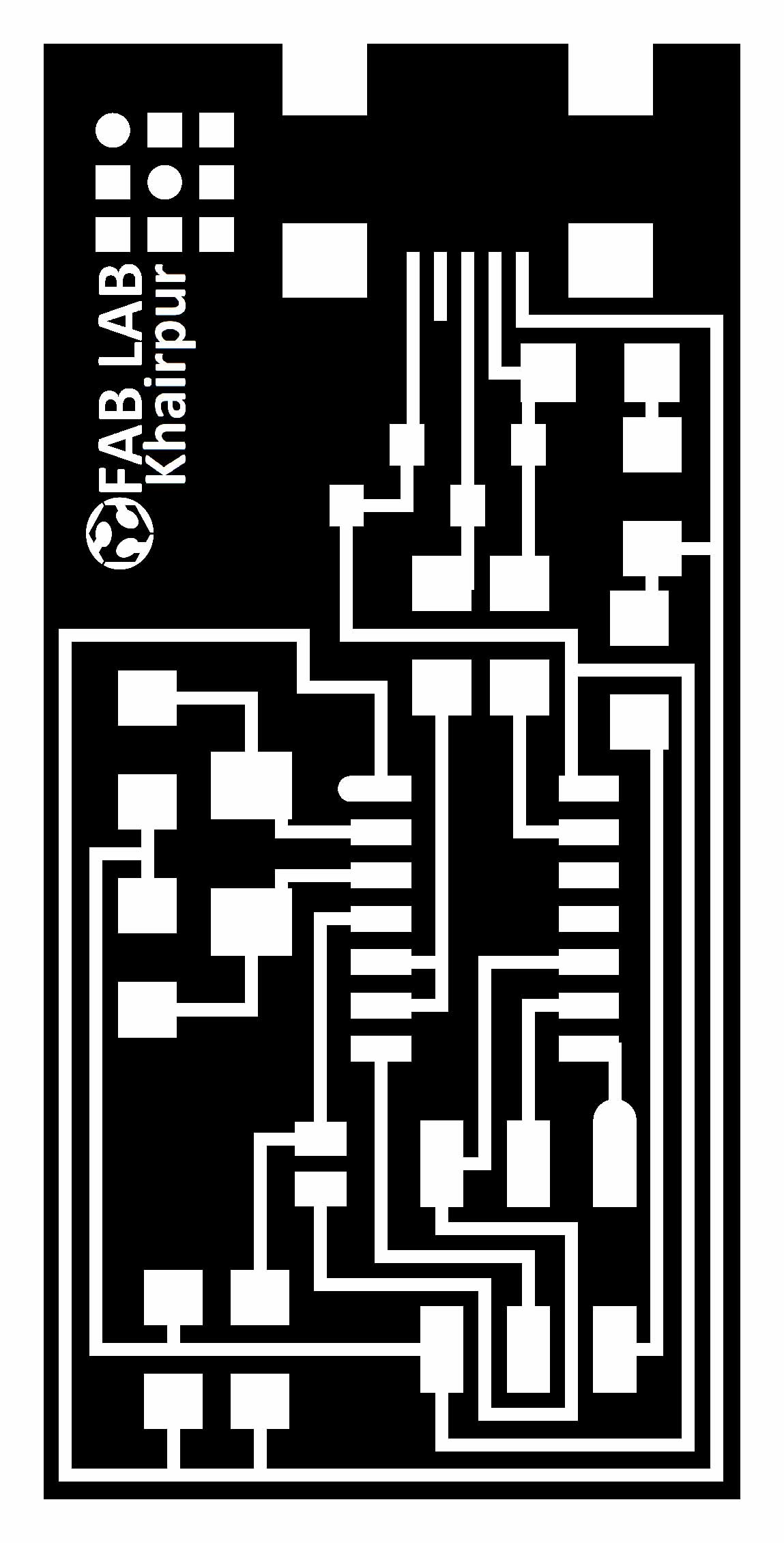
Outline cutting file

traces file
I used same method which I mentioned above to make PCB using Roland SRM-20 Machine. Firstly I enlist all the components which I need to make a development board
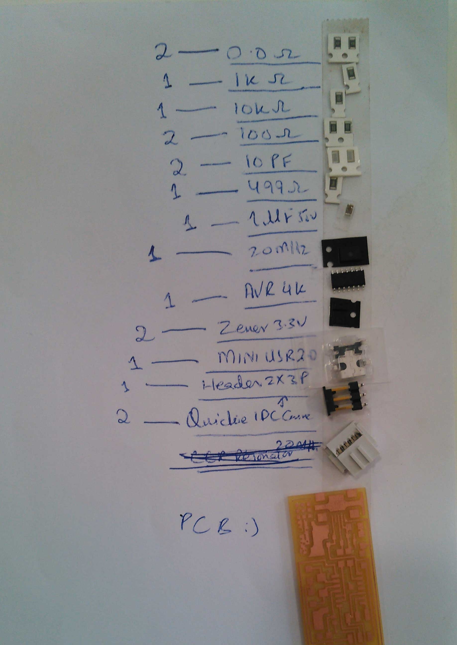
List with components and PCB
After soldering my first pcb board is made, but I dont like the soldering in it so I make one more.
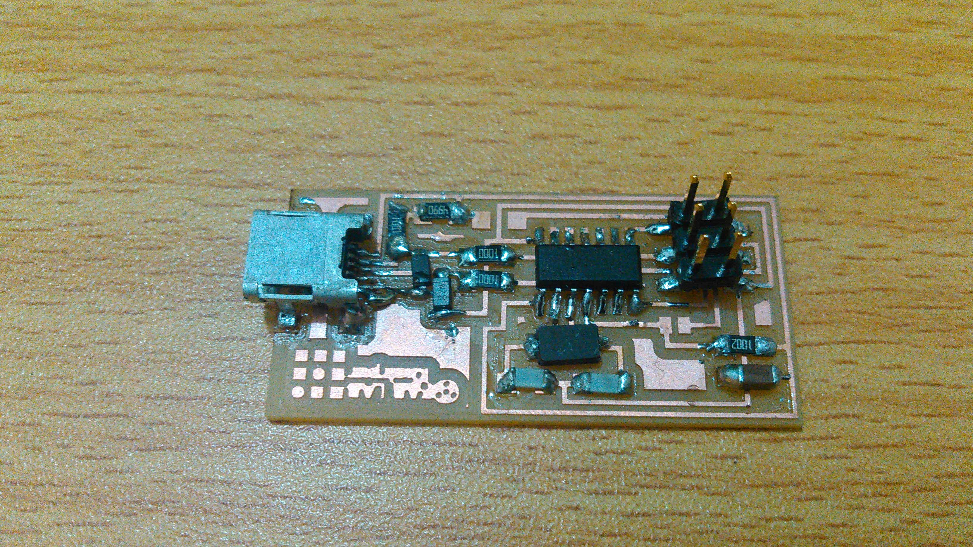
1st development board
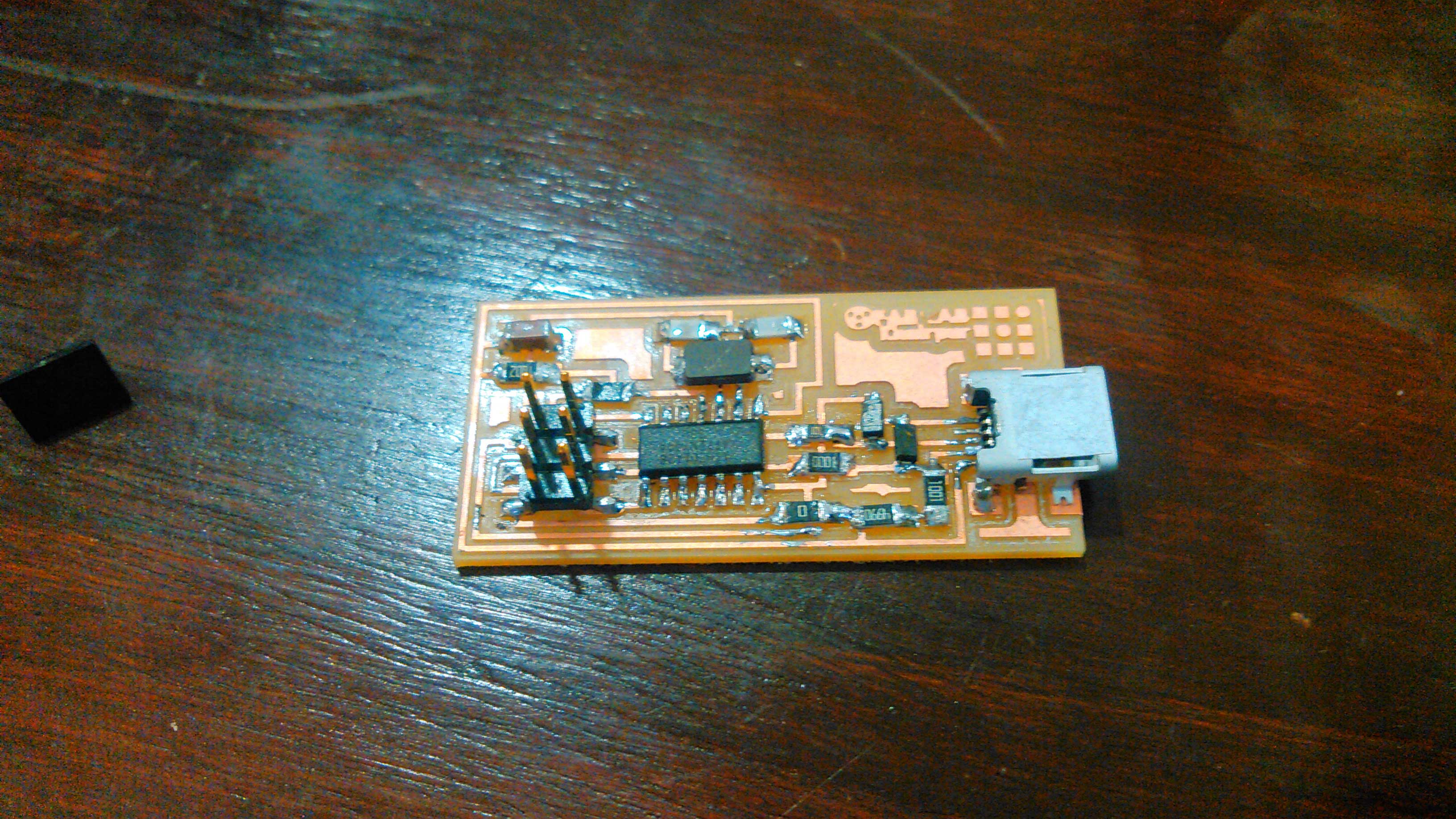
2nd development board
Uploading Program in the board
For burning program in development. I use linux because it is easy to work on it. We dedicate our Lab one pc for Linux and installed Ubuntu in it. After installation of Linux OS I done this steps, I forgot to take screen shots thats why a history of commands in terminal shown below:
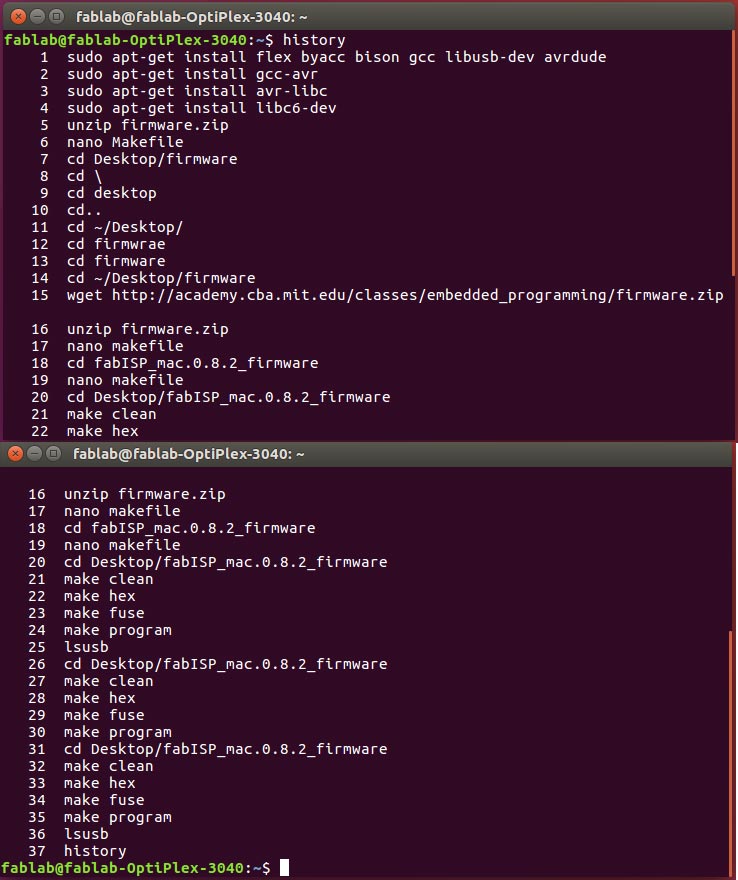
history of installation avr, GCC and libraries
Connecting both development board on PC one for developing and other for 1st one development
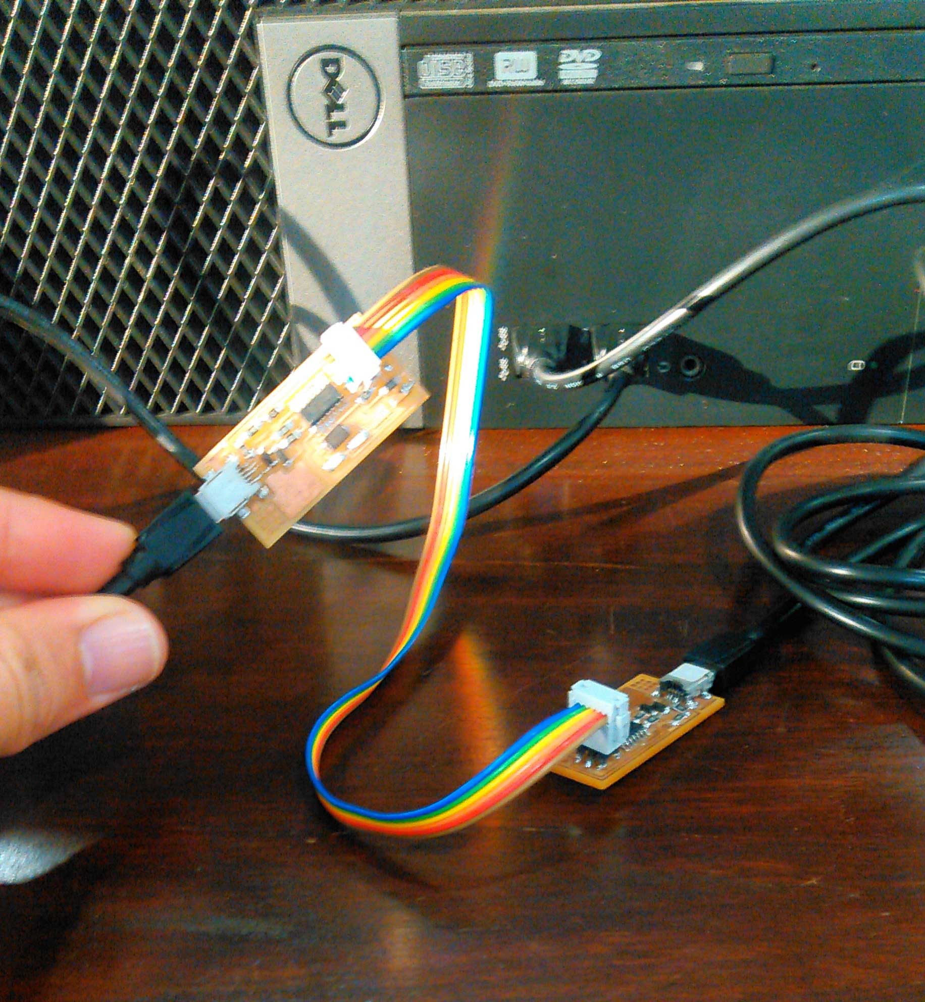
a development board is developing by development board
after connecting both cables I locate FabISB folder which is on Desktop and run command "make clean" and "make hex"
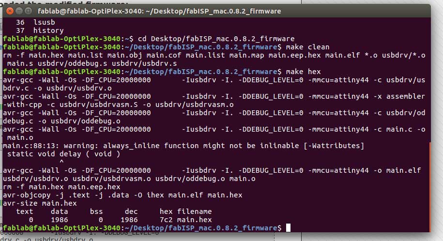
"make clean" and "make hex commands"
to set fuse I used command "make fuse" then program the board we are using "make program" command
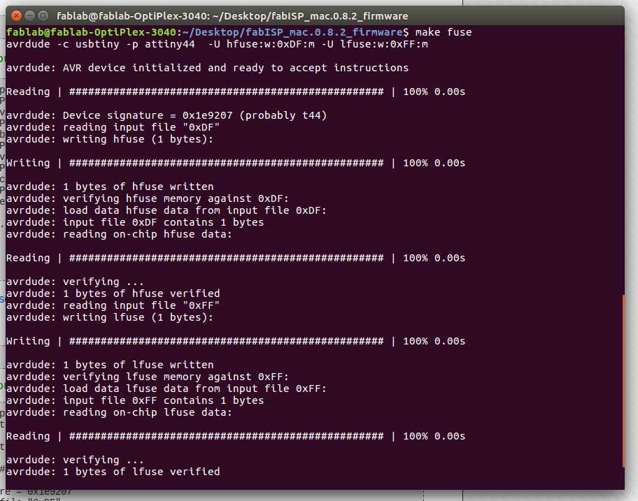
setting up fuse
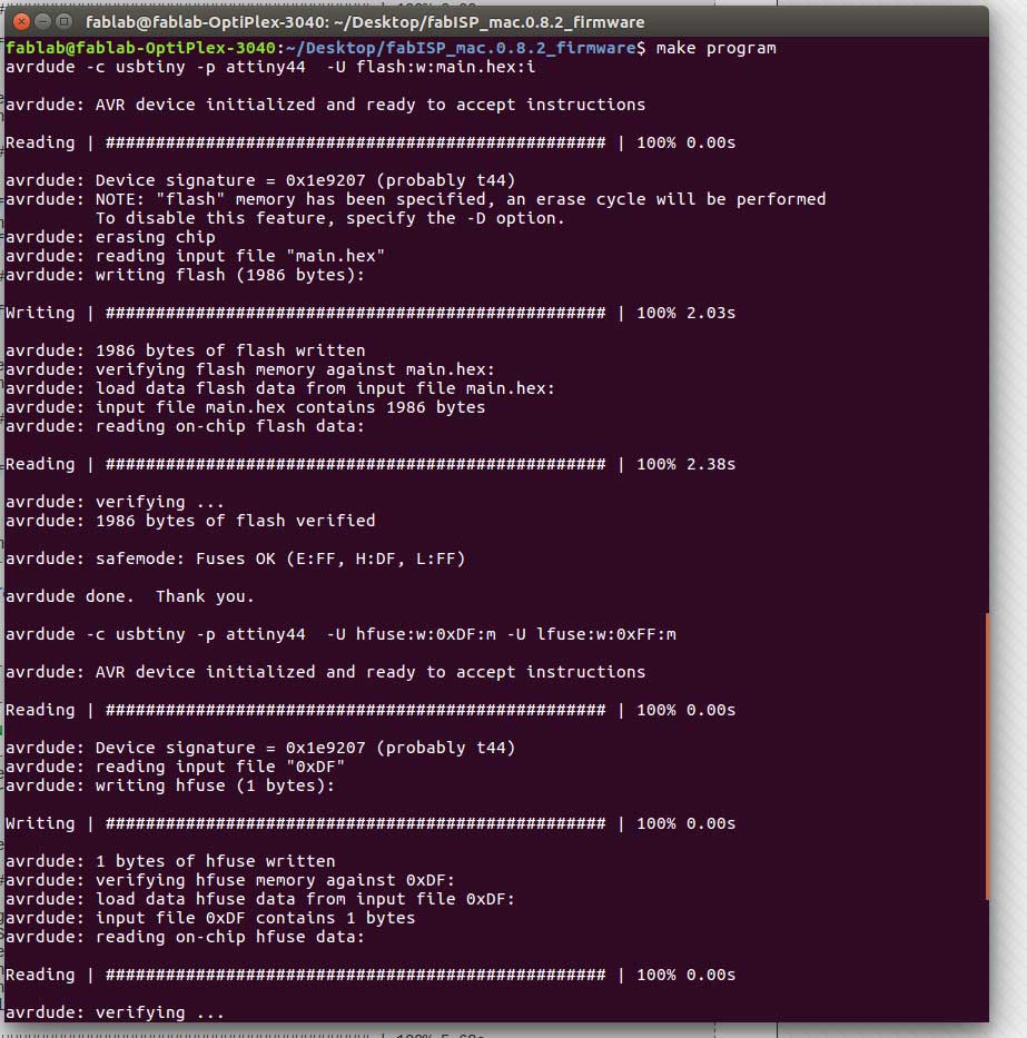
make program
Now to check either it is working or not
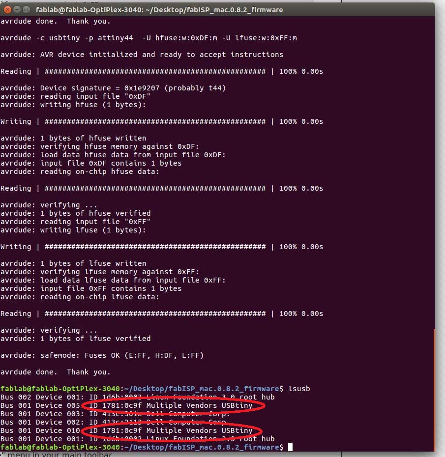
It is shown two development boards are connected
"Click here"to download all files of this week

This work is licensed under a Creative Commons Attribution-NonCommercial 4.0 International License