
|
| Sukkur IBA University Merit, Quality, Excellence |
WEEK-7
Electronics Design
Lecture & Recitaton of a Week:
Lecture on 28th of February, 2018: Electronics Design by Neil Gershenfeld
Recitation on 5th of March, 2018: bio academy by Kate Adamala, David Kong and Jean-Michel Molenaar
Tasks for a Week
- group assignment: use the test equipment in your lab to observe the operation of a microcontroller circuit board
- individual assignment: redraw the echo hello-world board, add (at least) a button and LED (with current-limiting resistor) check the design rules, make it, and test it extra credit: simulate its operation extra credit: render it
Individual Assignment
Back to PCBs
As an electronic engineer redrawing the echo hello-world board is not a challenging for me if a traditional method of PCB Designing is to be followed. In my bachelor maybe in 3rd or 4th semester I made my first PCB board with the old traditional method in which we have to print the circuit diagram on glossy paper then transfer the toner from glossy paper to copper board using Iron, then etch the board using hot water and Ferric Chloride which removes unwanted copper from board, after that step we use steel wool to remove toner so we get only copper traces which we need on PCB. The method was full of frustration that it discourage me to make PCBs so I move back to my veroboard and stuff and make my circuitry on that. Then in 5th week when I saw SRM-20 milling machine to make beautiful and accurate PCB's for me then I unwillingly decided to make PCBs again.
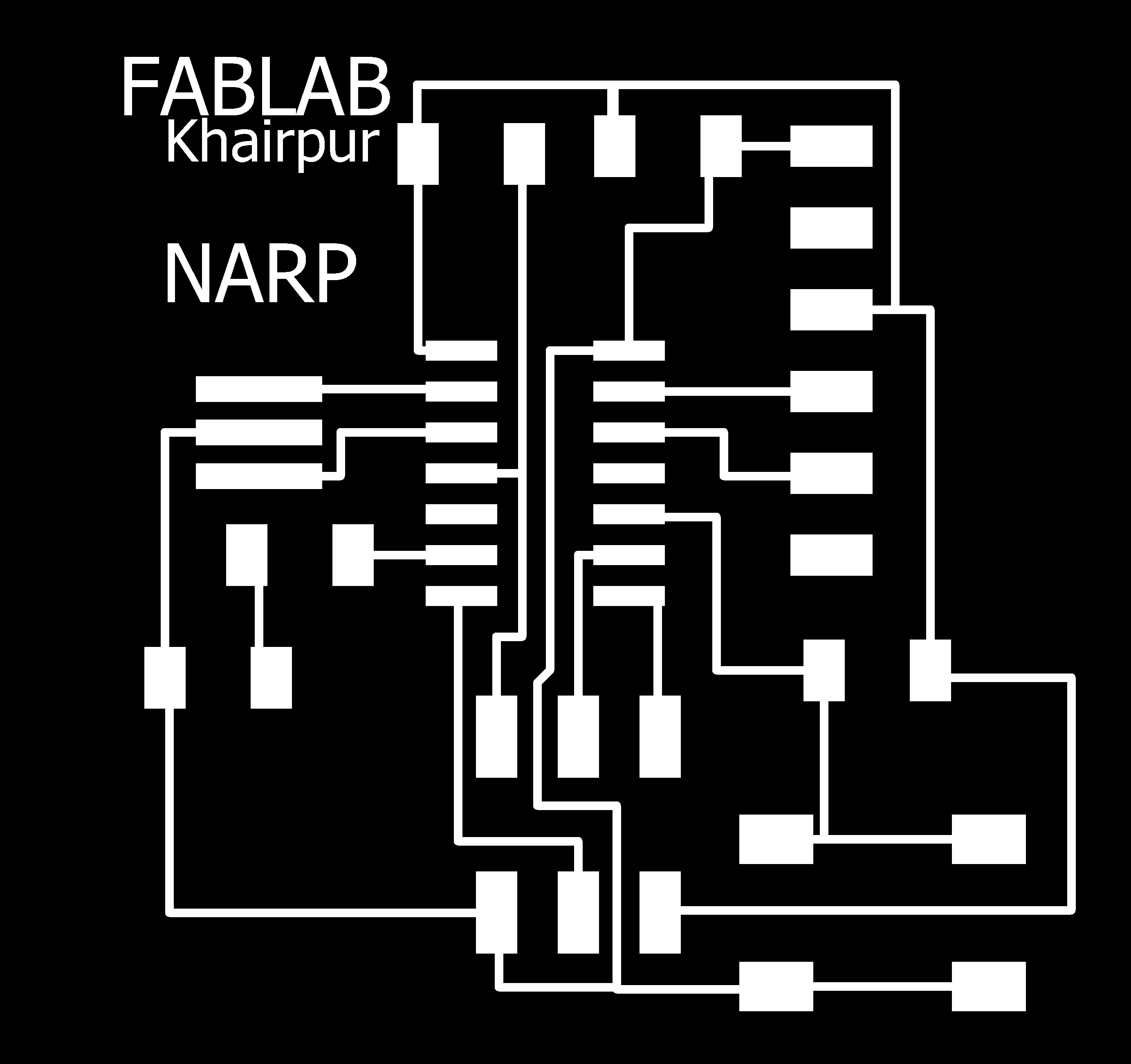
Redraw the Echo Hello-World Board
Before starting to work on weekly task, I went through previous student pages (specially my instructors), understand their work, recommendations and learning from others mistake is the quicker way to resolve issues and complete the task. To redraw the echo hello-world board there are several steps to follow which I describe below:
- Download and install any PCB designing software and get familiar with it
- Download and install FAB libraries to get the list of components which are available in FABLAB
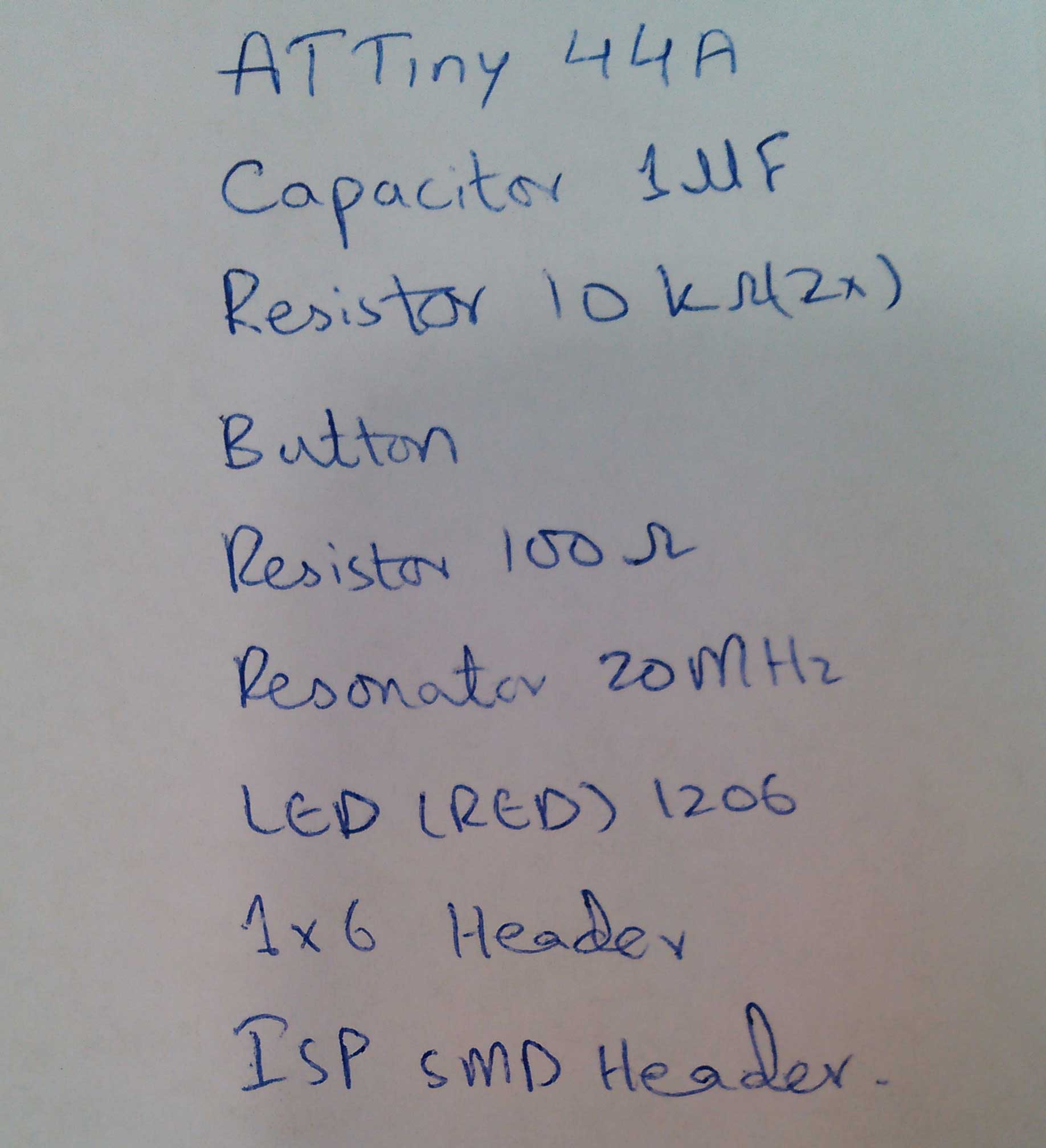
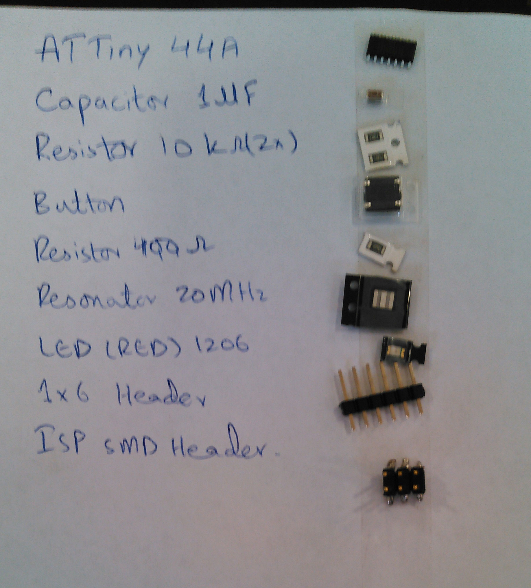
- Enlist the components which is seen in given hello-world board.
- Redraw the echo hello-world board by adding input and output in it i.e, atleast one button and LED with current-limiting resistor
- Generate .rml files of traces and outer boundary of PCB
- Mill the PCB by giving .rml file to ROLAND SRM-20 milling machine
- Sold the components on PCB
- Test the board by burning program in it.
CadSoft Eagle:

First of all to start PCB designing we need a decent software to work on. I choose EAGLE (Easily Applicable Graphical Layout Editor). The software is easy to draw the circuit and recommend by most of others. CadSoft Eagle is not a free software, to download a free (lite) version Click here. To start and getting familiar with this software I found this video helpful:
FAB Library:
After installation of CadSoft EAGLE we need to include fab library in it, the library help us to get the proper PCB layout of the components in software which are available in FABLAB. The FAB library is downloadedfrom here.
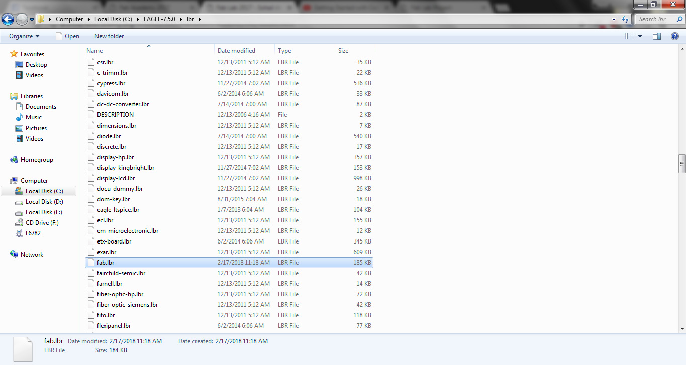
- If installation of a software is in default location then to include fab library we just need to paste the library in the folder C:\EAGLE-7.5.0\lbr.
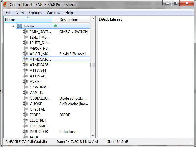
- After opening EAGLE, a Control Panel is shown on screen, we can check in it either library is included or not
Redrawing the Circuit:
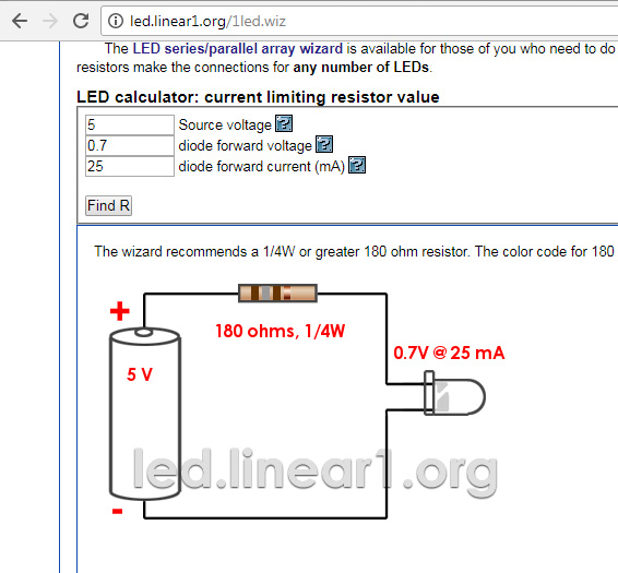
- Now we are able to use fab library layouts to make PCB. Before designing it is better to enlist components we need to make a circuit. Our work is easy the circuit is already made we have to add an LED and a button in it. LED needs a current limiting circuit and we have to make a pull-up circuit for button, these two little parts of circuit need a resistor to limit the current. I selected 10k ohm resistor for button and for limiting the current it is calculated to use 180 ohm rsistor but for safety I am using 499 ohm.
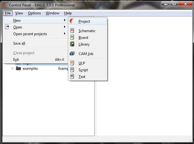
- After getting the list now we can start new project by selecting "New" in "File tab" then select "Project"
- After clicking on Project an "Empty Project" is made in Eagle folder. Rename it and right click to open schematic
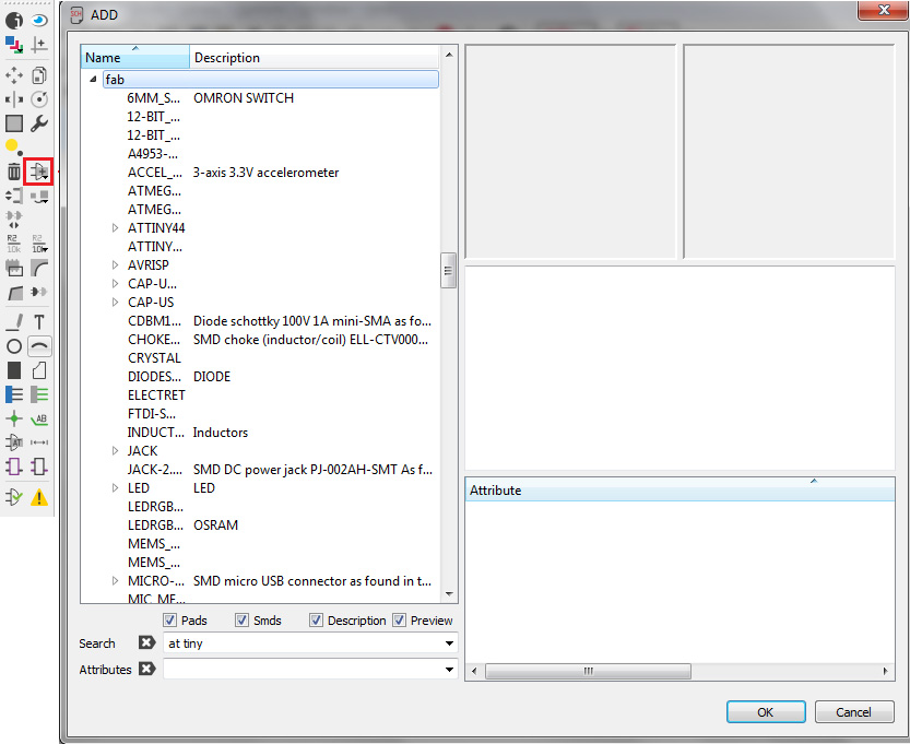
- To make schematic of a circuit we have to add components in it using "Add tool" in left toolbar, it opens the window where we select the components from Fab library
- Adding the components in the list and to join them a schematic is completed and after running ERC (Electrical Rule Check) command it generates no error and 3 warnings which are because of no connection on 2 pins and button value is not set.
- Now to shift the schematic to pcb board view where we are able to make tracks

- after making tracks, we are going to save the file in png format.
- the png file is processed in MS Paint for making traces and outline file then giving to "mods.cba.mit.edu" to generate .RML files (detailed method is described in week-5)for further process in Roland SRM-20 Milling machine

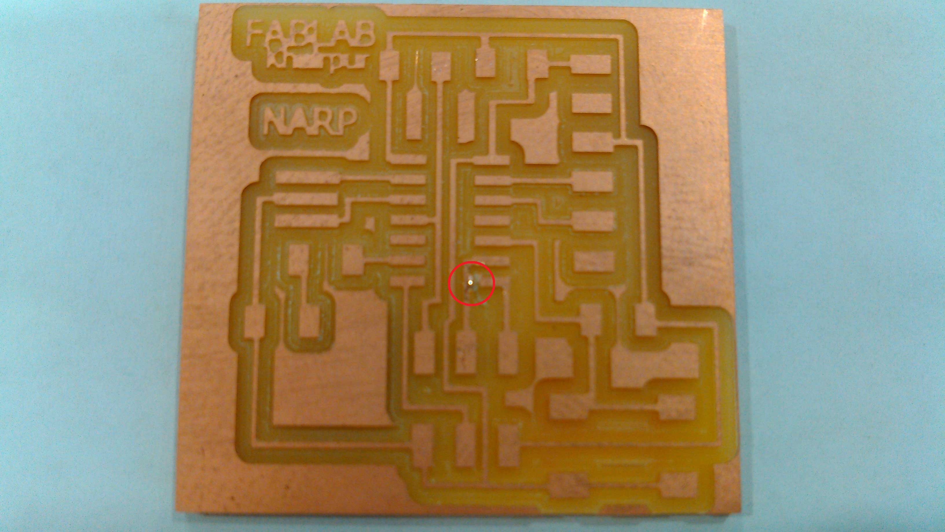
Milling and Soldering
- .rml files are given to Roland SRM-20 Milling Machine. For traces 1/64 drill bit and for outline we are using 1/32 drill bit
- after checking the tracks I found 2 pins are connected, so I disconnect them from each other remaining circuit is looking fine
- arrangement of component for Soldering
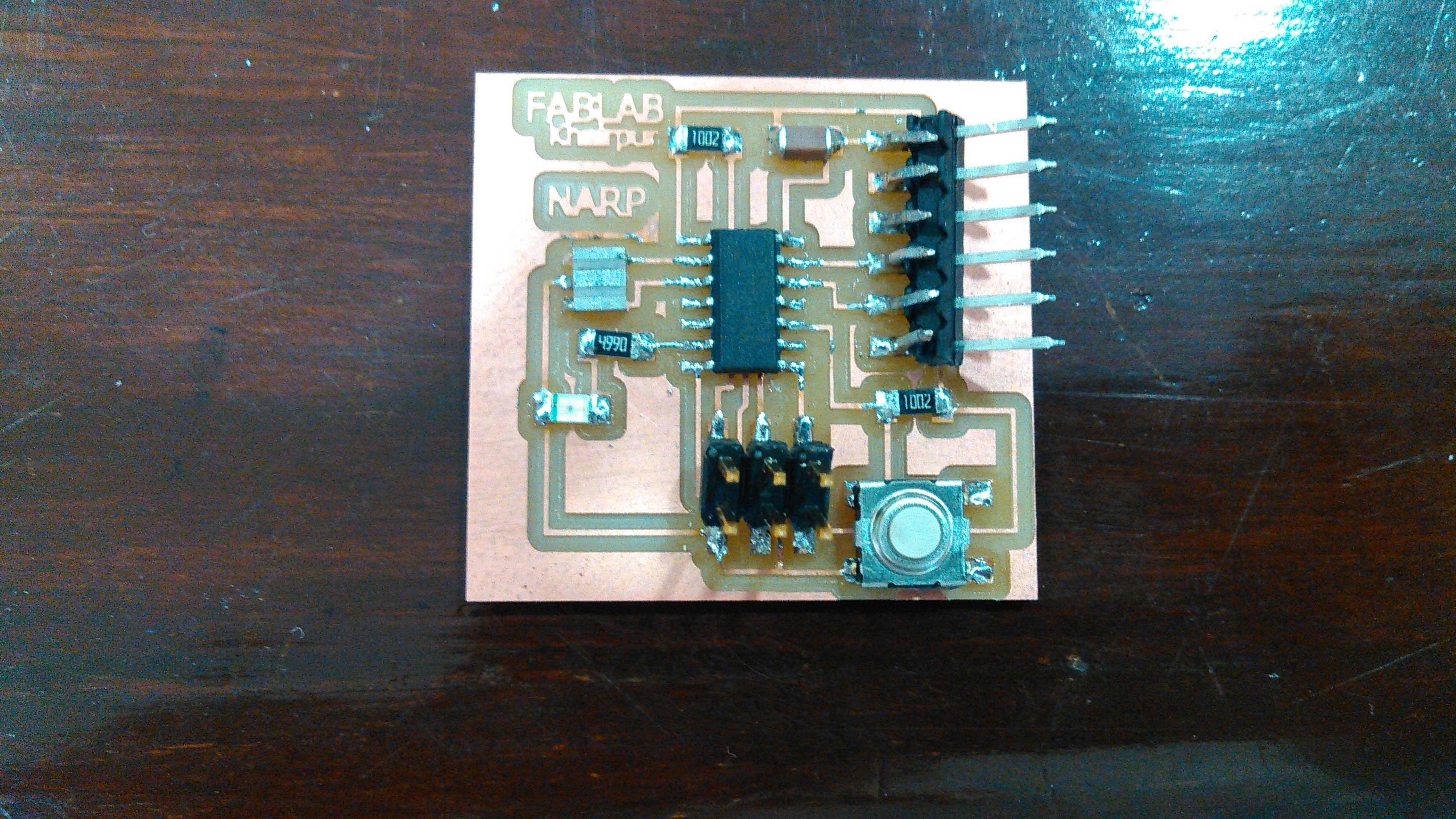
- I soldered all the components included one output (LED) and input (button) in a circuit.
Program Burning and Testing
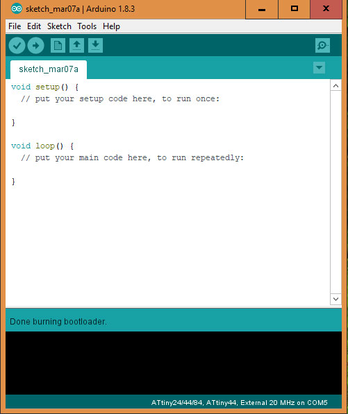
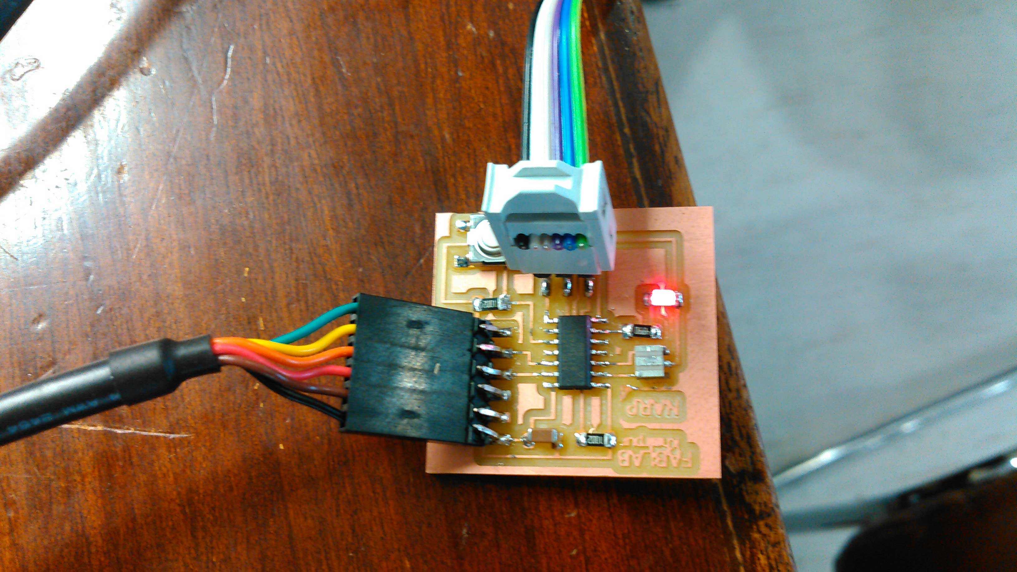
- After complete the soldering the burning and uploading part remains, for this we are using our week 5 development board and FTDI Cable to burn the code in echo hello-world board. I am using Arduino IDE to upload code, first we burn the code,then we upload the blink code in hello-world board.
Done burning bootloader
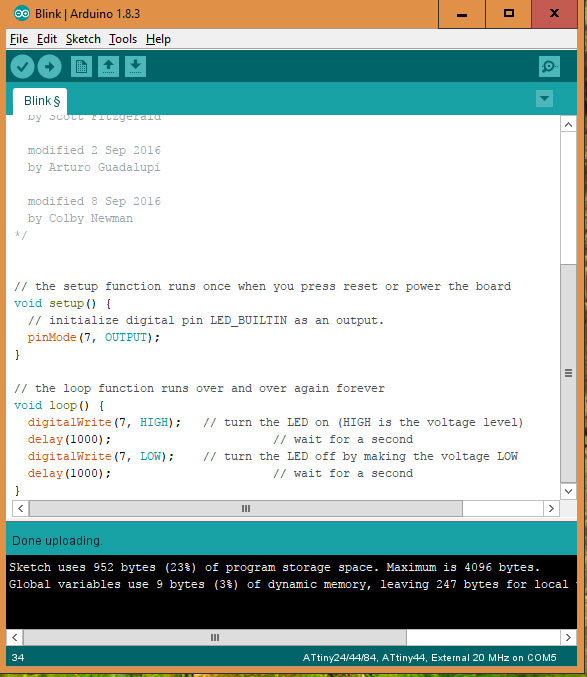
Code Uploading done
Blink code is running in a circuit. LED blinks after every 1 sec
Group Assignment
Multimeter
"A multimeter is for electronic engineer as stethoscope is for doctor". It is most convenient and helpful equipment when we test or measure electronic components. We decided to check component in echo-hello world circuit using multimeter to confirm the values of components and to check either they are in working condition or not.
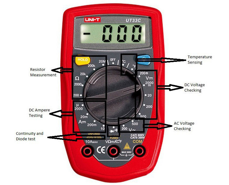
Multimeter function description
Continuity and Diode Testing
To test the continuity and diode first turn the dial of multimeter on continuety testing function which is mentioned in above picture. Continuity test is done by checking circuit tracks with probes, if beep occurs it means that tracks are connected if there is no sound of beep or shown "1" on screen it means that tracks are not connected.
connection testing from attiny 45 ground to FTDI ground
button testing multimeter beeps when button pressed
To check the LED we placed the black probe on cathode side (which is marked green in our LED) and red probe on anode side, if LED glows it means that it is in working condition.
LED testing
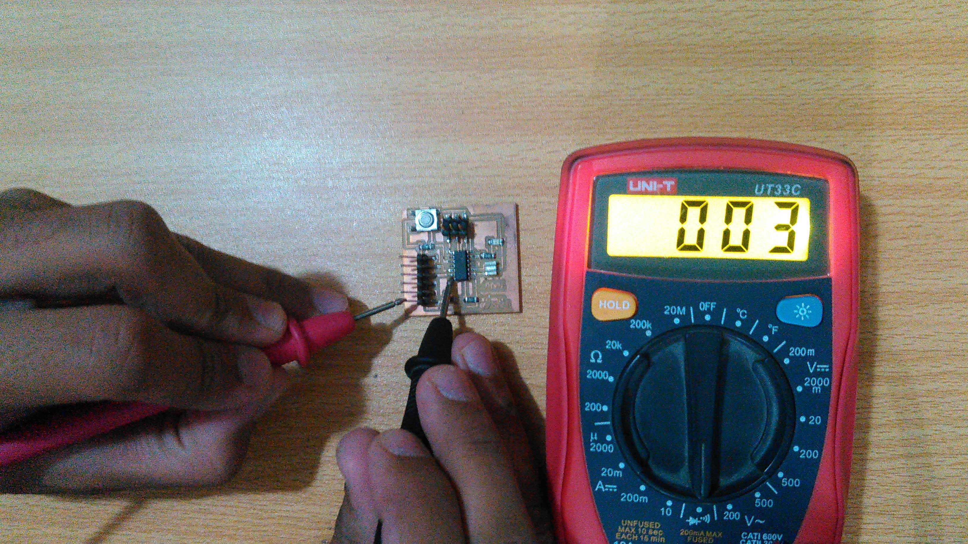
Measuring Resistance
In a echo-hello world circuit we have 3 resistors, 2 are 10k ohm and 1 is 499 ohm resistor with 1 % tolerance. To check their values we moved the dial to "20k" in resistor measuring portion and measured them.
Measuring resistance
Voltage Supplies
A circuit is powered via FTDI cable which has 6 pins in which black one is GND and red is VCC. We checked the potential difference by placing black probe on GND pin and red probe on VCC pin to check the voltage. Then we check voltage in circuit by powered it with FTDI Cable.
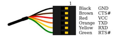
FTDI Cable pinouts
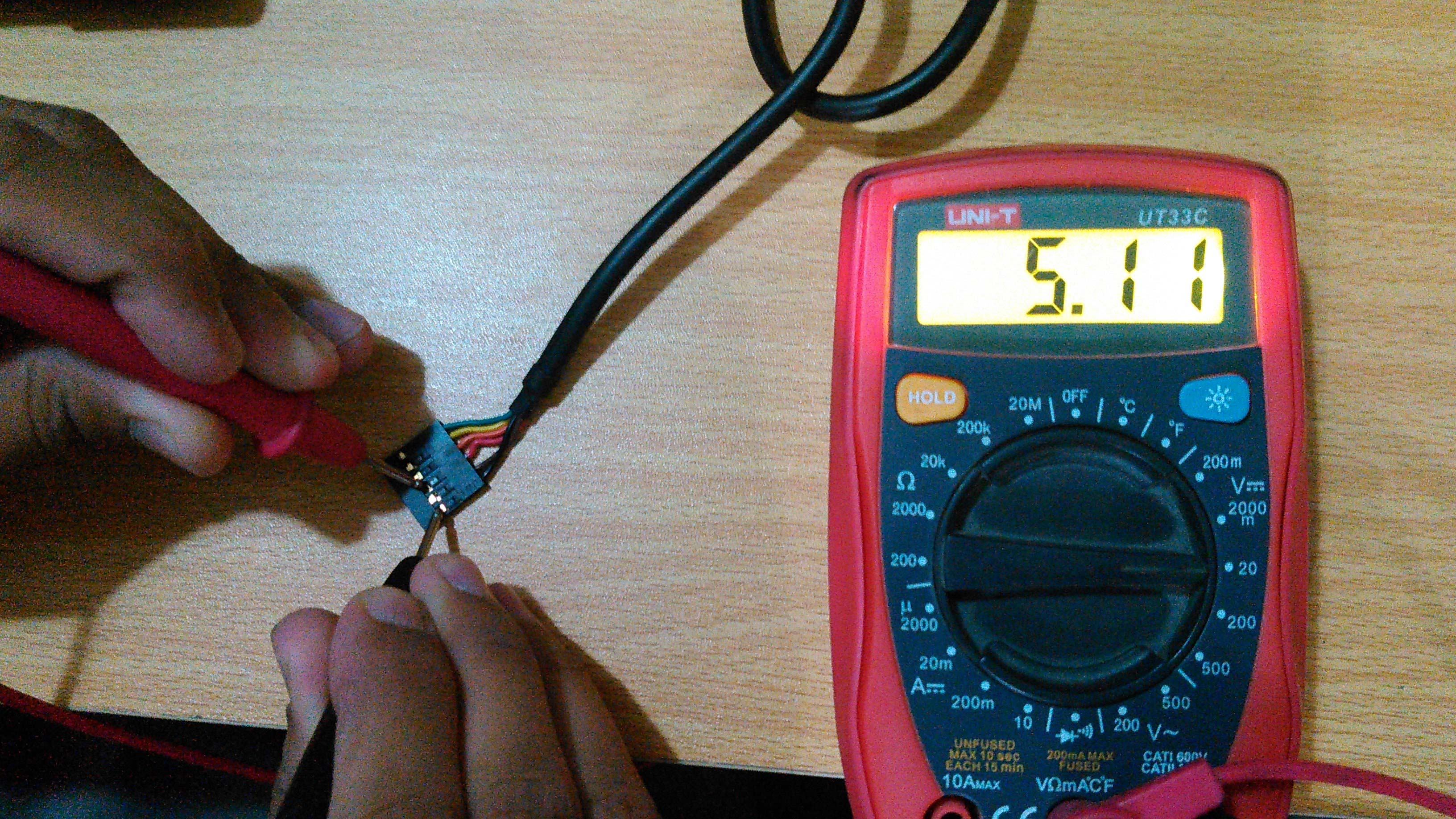
5V from FTDI Cable displays in Multimeter
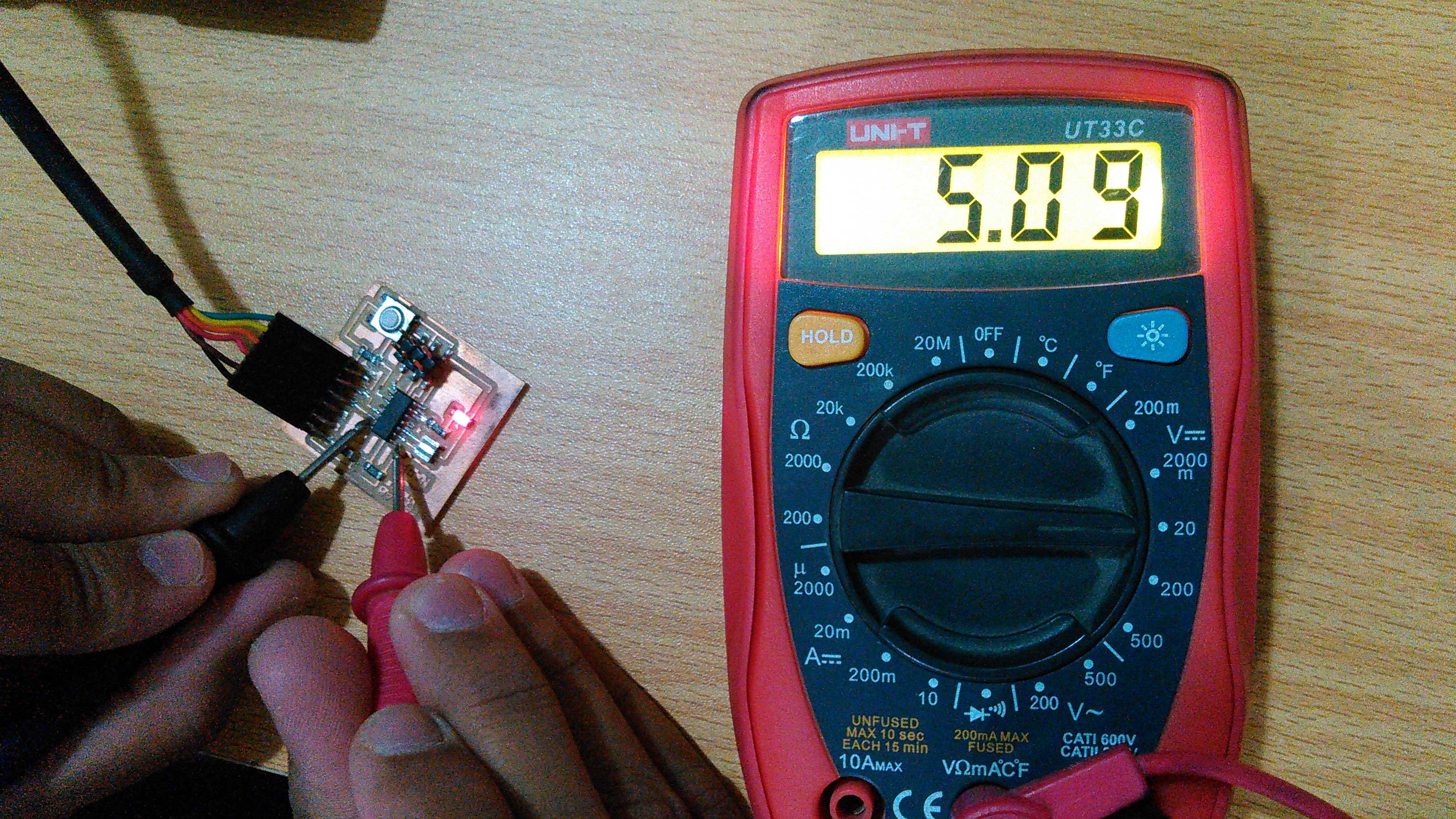
5V Voltage in a circuit
"Click here"to download all files of this week

This work is licensed under a Creative Commons Attribution-NonCommercial 4.0 International License