Assignment 05
- Group assignment: Characterize the specifications of your PCB production process
- Individual assignment: Make an in-circuit programmer by milling the PCB
Group Assignment:
For group assignment, we have to characterize the specifications of PCB production process and for that we are using Roland monoFAB SRM-20 Milling machine. For learning process in both group and individul assignments we are using basic PCB Board which is FR-1. We are fabricating a Traces-width board, which has a traces which is very near in different sizes. For cutting and traces we are using 1/32 and 1/64 drill bit respectively.
Fabricating PCB
We are using these png files for trace and outline
 Group task traces, tool used 1/64
 Group task outline, tool used 1/32
After generating RML we send both files to ROLAND monoFAB SM-20 Machine. following steps below to show how machine works
- Place PCB on board
- Open VPanel for SRM-20 in Desktop
- Change the drill bit
- Select origin to x/y and z axis by changing values of x, y and z axis from where it should be start.
- Adjust drill bit until it touches PCB board
- Change Z-Axis value little bit to dig PCB board slightly, then set new value of Z-Axis as origin.
- Click on "Cut" and locate .rml file which we want to use.
- Click on "Output" to start the process.
 Group PCB Fabrication uisng Roland monoFAB SRM-20 Machine
Individual Assignment:
The Individual assignment was completed in portions and each portion several steps in it. So, I will be explaining these portions below:
1. What is In-Circuit Programmer?
In-Circuit Programmer is a circuit that we connect with our PC and on the other side of this, is our Micro-Controller based circuit. The reason why this circuit is so crucial is it lets us program AVR Micro-Controllers without removing the chip from circuit.
In order to make an ISP, I started with downloading the PNG files of circuit from the class schedule tab, which are shown below:
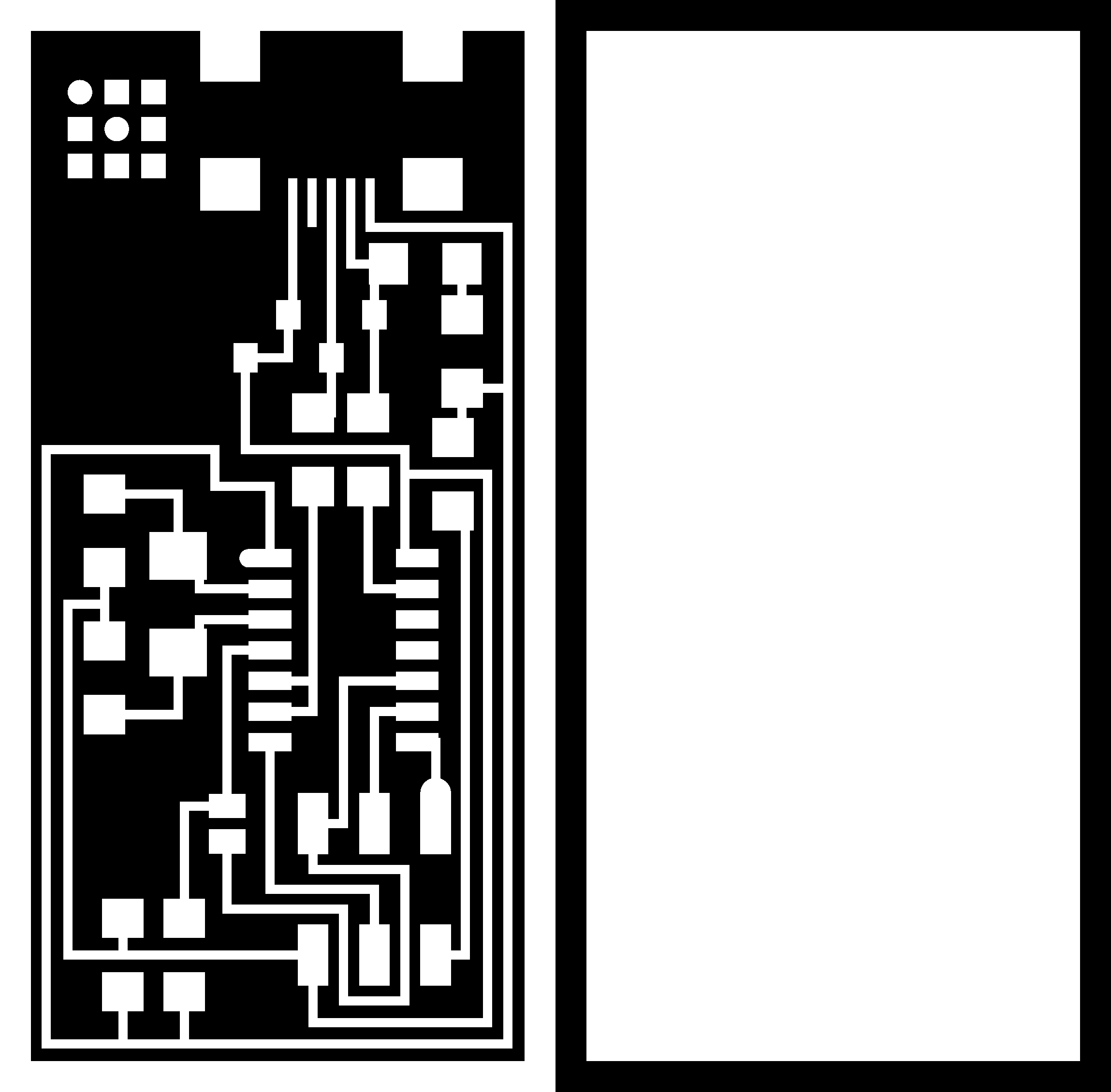 Circuit traces and outline
2. RML Files
In order to Mill the PCB layout given in the pictures, we need to convert them into RML files. These PNG files can be converted into RML files by following steps:
- Go to http://fabmodules.org/
- Select Image(.png) from the "input" dropdown menu, and select the image that you want to convert
- From the next dropdown menu "output format", Select Rolland mill(.rml)
- After that is the "process" dropdown menu, Here we will be selecting the mill size that is PCB traces(1/64) for Schematic design and PCB outline(1/32) for circuit outline.
- Now from right side, we will select the model of machine that we are using for milling purpose. In my case it is SRM-20
- Once the model is selected, then we will clear the values of x0(mm), y0(mm), z0(mm) to zero.
- Finally, click the "calculate" button, and it will start generating the RML file.
- When the process completes, you can see a different picture showing many directional arrows over circular paths. These are the paths that will be followed by the machine while milling the circuit.
 GIF image showing the steps performed for generating RML file of traces
 GIF image showing the steps performed for generating RML file of outline
3. Milling the circuit
We used the
Roland SRM-20 machine for milling, and operated it using the VPanel software. It is connected with the PC through USB cable.
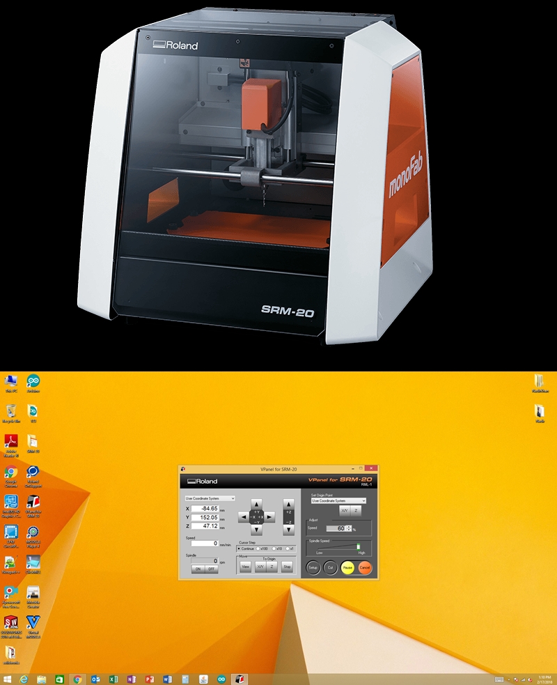 Roland SRM-20 and VPanel
Mentioned below are the steps performed on SRM-20:
Roland SRM-20 and VPanel
Mentioned below are the steps performed on SRM-20:
- Place the PCB carefully, make sure it is positioned in the space between the holes of base plate. These holes define the limit of movement of drill along X-axis.
- Insert tool in the drill, "1/64" and "1/32" for "traces" and "outline" respectively.
- Close the front cover, turn on the machine and open the VPanel software in your PC.
- Using the buttons available in the VPanel software, move the PCB to the desired position. The tools must be placed over the reference value of circuit, that is Bottom-Left.
- Once you set the values of X and Y, click on the "XY" button in the right section of software to save those values as the Origin points.
- After setting XY values, now set the value of Z carefully, otherwise the tool can be damaged.
- When you observe that tool is just touching the PCB, switch on the Spindle and press it down using the Z-axis values unless you see the milling through the copper. Set the Z axis value at that point
- Click the Cut button and load your respective RML file
- Press the Output button and wait for the traces to complete.
- As the machine completes milling the traces, change the tool for outline(1/32) and load the RML file for "Outline"
 Gif showing the steps performed over the VPanel Software
4. Soldering the Components
Soldering was the fun part, as it was the first time i was doing soldering of SMT components.
Finding the components from the inventory becomes easy when you are the one who managed the inventory :D
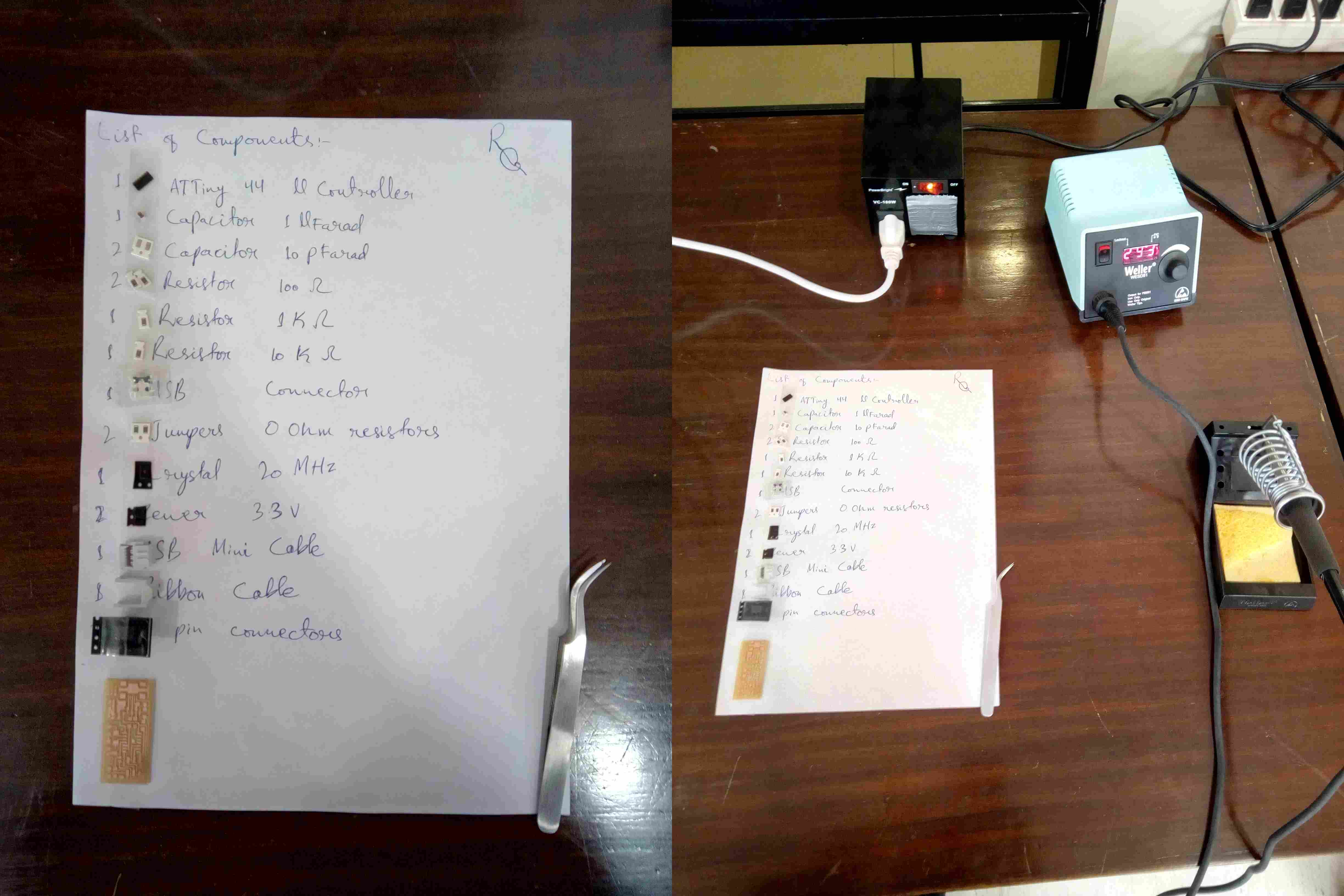 Components list along with components and Soldering Station
These are the tools quite necessary while you are soldering SMD components:
- Soldering wire
- Soldering remover
- Tweezer
- Soldering iron
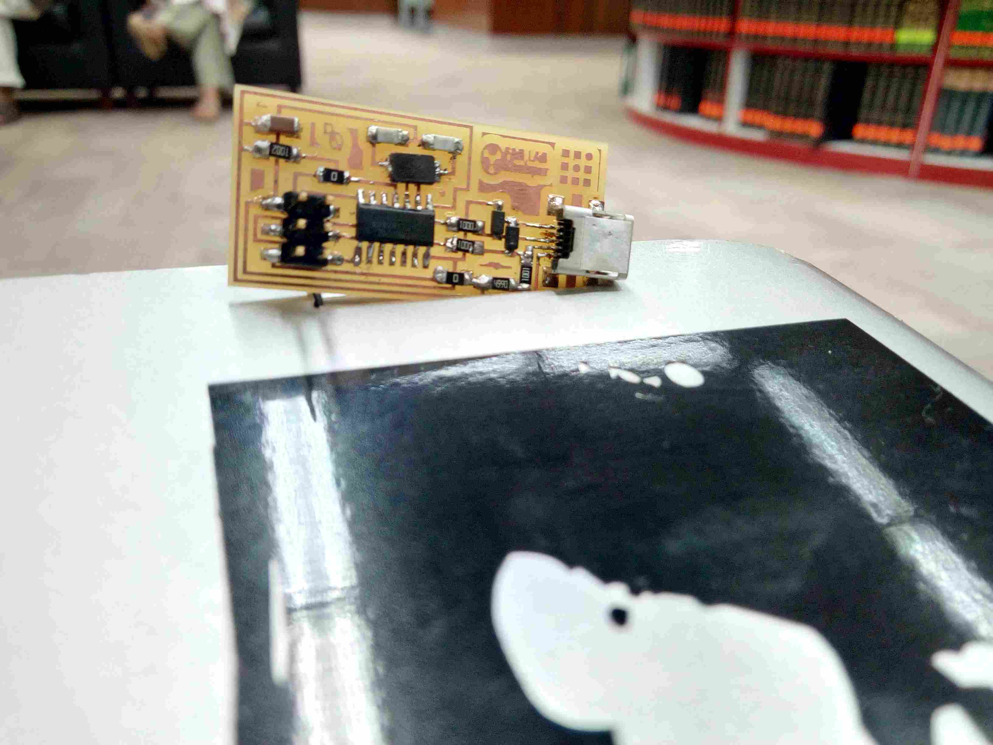 ISP Circuit after soldering
5. Programming ISP
Now comes the most crucial part that is programming, for programming our circuit we had some issues while programming it from Windows operating system. Inorder to come up with this situation, we installed Ubuntu operating system in one of the PCs available in our Lab.
For programming ISP using Ubuntu a brief step-by-step process is explained Here
The Softwares and drivers necessary can be downloaded from below mentioned Links:
After completing above steps correctly, go to Terminal of Ubuntu and Type following commands:
- make clean
- make hex
- make fuse
- make program
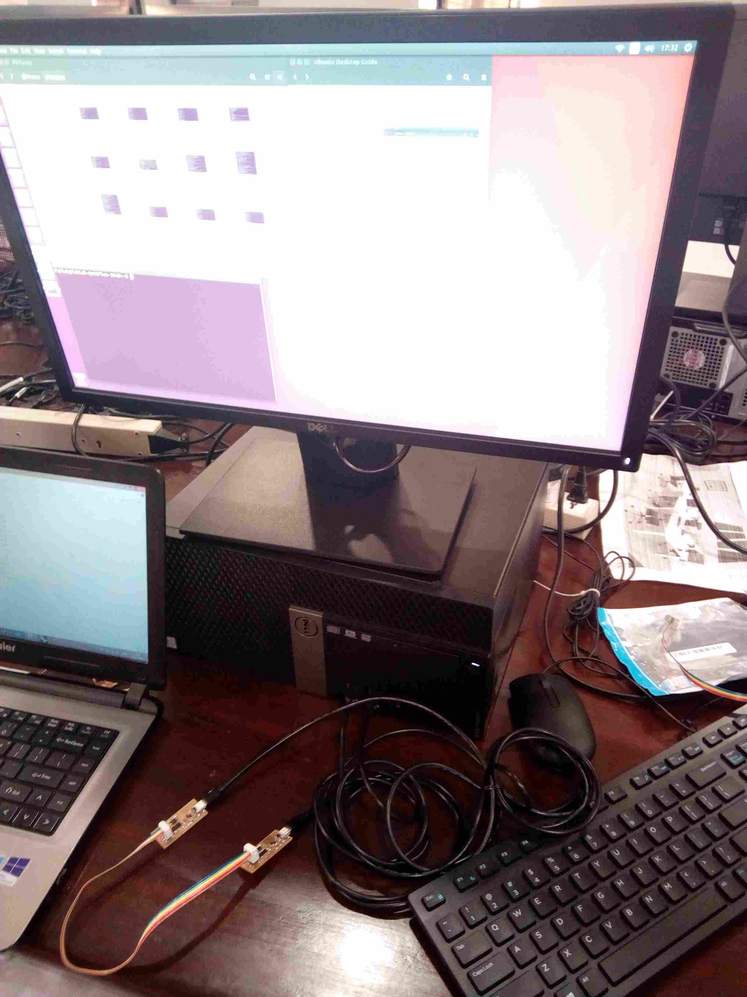 Connection of devices with themselves and with PC, while programming
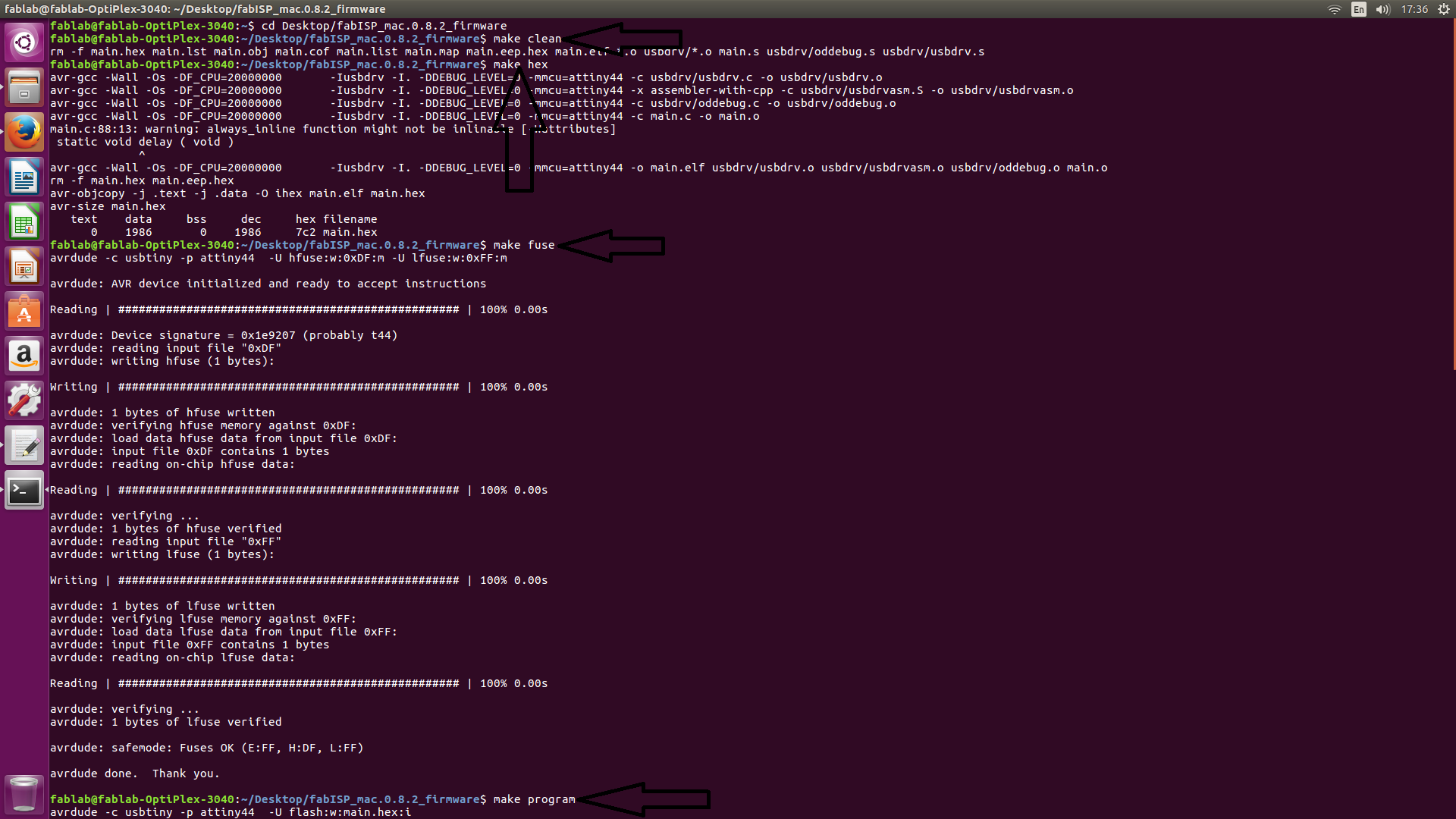 commands and their result in Terminal
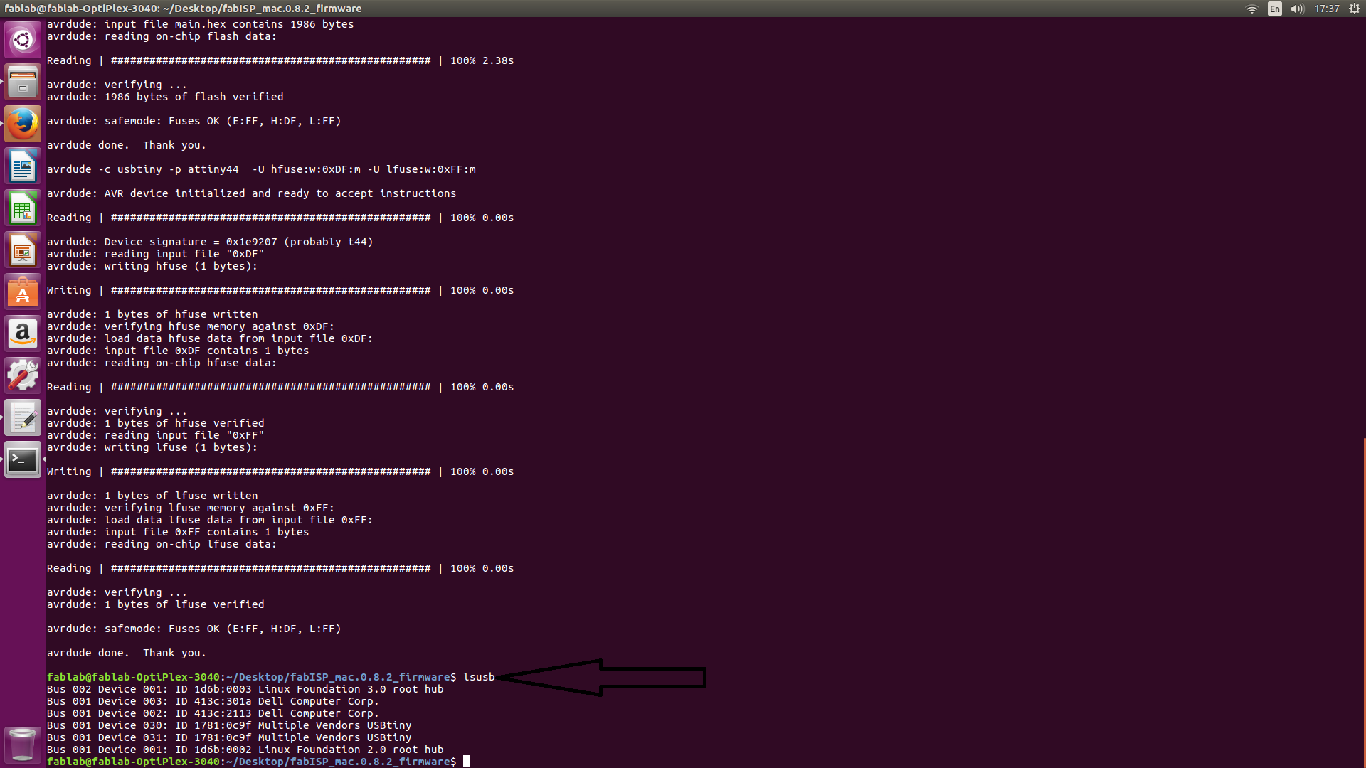 typing "lsusb" shows that both the connected devices
6. Removing Zero Ohm resistors
The last step to make your device an FAB ISP is to simply remove the Zero ohm resistors, then your final circuit will look like this
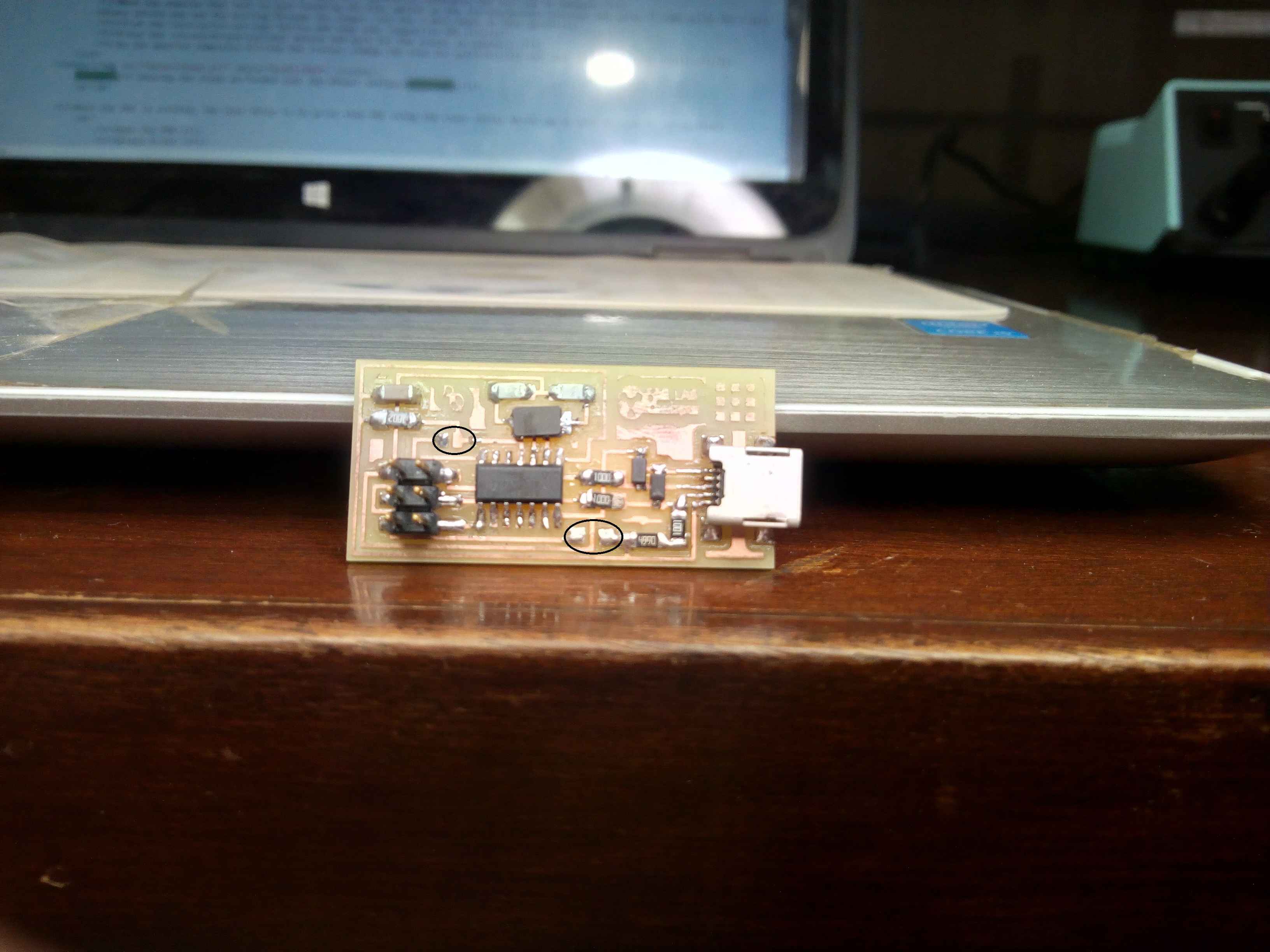 Final Circuit without zero ohm resistors
7. Installing drivers on PC
To operate it from a windows based PC we have to install the drivers for this programmer. Just download this
Adafruit Driver Installer
Once the driver installation is done, you can plug in your device and check it in the "Device Manager" as shown below:
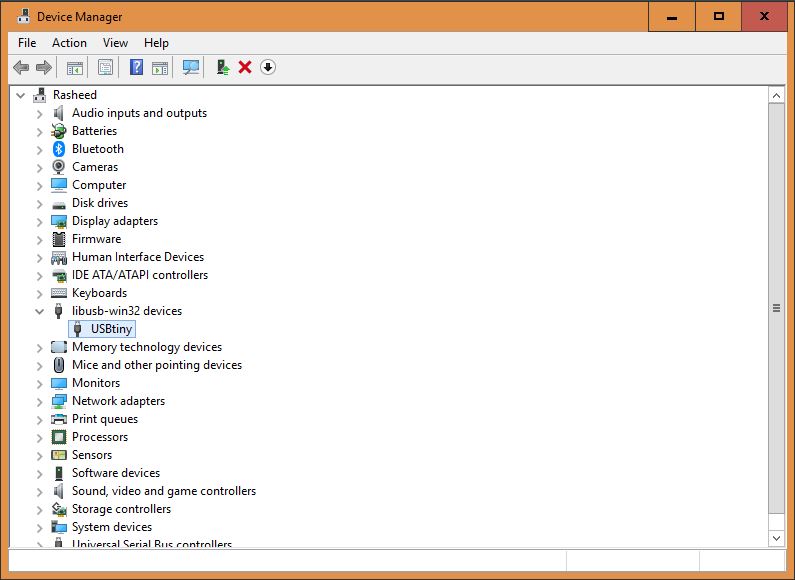 Device manager showing ATTiny
Congratulations! Now your device can be used FAB ISP :)
All the Files of Week 5 can be downloaded from Here.
« Week4
Week6 »
Device manager showing ATTiny
Congratulations! Now your device can be used FAB ISP :)
All the Files of Week 5 can be downloaded from Here.
« Week4
Week6 »