Final Project Presentation

A 3D GIF
3D GIF made on Lixie, showing a running man, Lixies are awesome ;)
Project Proposal
Intorduction to the Lixie Tubes!
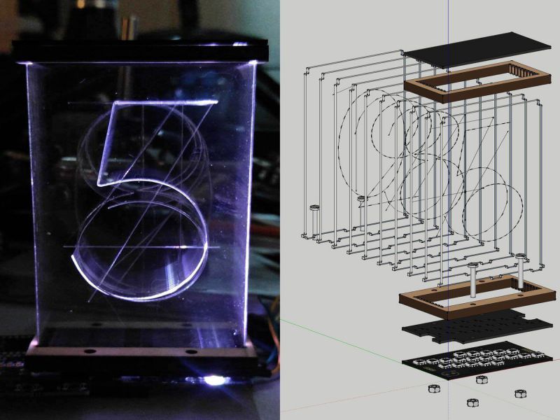
Lixie is an edge-lit acrylic display for any numeric information you can think of! Clocks, temperature displays, hit counters, and more. Always being a fan of the beautiful typography of a Nixie Tube, the Lixie is a modern spin!
The Lixie has extremely simple setup, just connect the 5V, GND, and DIN pads to an Arduino and use the Lixie library to write a digit to the display! That's it! No HV switching, PCB footprint, or worries!
Since the Lixie is just wired like a WS2812B strip, you can connect the DOUT pin of one to the next and show a number as long you'd like!
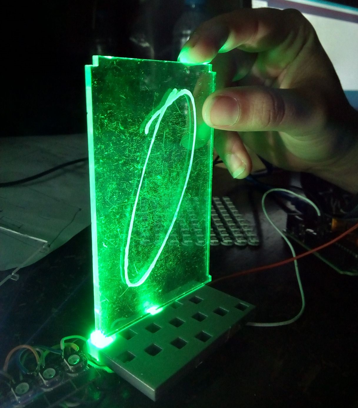
Below is the image showing a Single Number displayed on Lixie, and the internal structure of 10 acrylic sheets stacked together, PCB and footprints.
Why can LIXIE do?
A Modern Spin On A Retro Tech !
- Date / Time
- Temperature / Humidity
- Website Views
- Youtube Views
- Tindie Sales
- Or any number in any Arduino Project!
- They are compatible with ESP8266, Raspberry Pi and the entire family of Arduino Microcontroller
- Operate at low-voltage power
- Lixie is based on WS2812B LEDs, (or "Neopixels" Adafruit calls them), it can be used to make intresting displays just by using the basic digital fabrication ttols : 3D Printing, LAser Cut, Electronics Productoion, Interfacing and Programming.
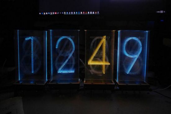
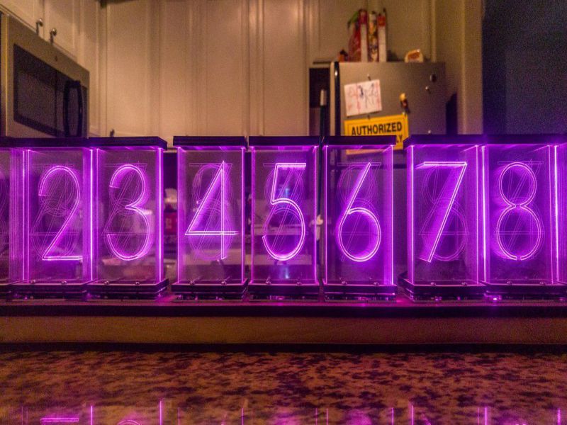
A clock made of Lixie digits.
How does LIXIE work
Unlike the Nixie Tubes the Lixie is based on, setup and use is EXTREMELY easy. Just connect the 5V & GND pins to your Arduino's, and connect the "DIN" pin to any of your digital pins. From there, it's just a matter of including the Lixie library and simple functions!
Lixie is designed as a WS2812B strip, meaning you can chain as many of these together as your power supply can handle! There are 20 LEDS on each board, but when used normally only two will be on at a given time.
The library also does all the work pushing each digit of an integer out to it's own display, so that if you have 4 Lixies, calling lix.write(314) will show " 314" or "0314" on them!
How is LIXIE different
Low Voltage
While traditional Nixie Tube displays took a dangerous 170V power supply, Lixie runs on only 5 volts making it safe for children, pets, and new hobbyists! Connector.
Self Driving
Lixie is based on WS2812B LEDs, which means that they don’t need any specialized drivers – just a microcontroller! Connector.
Chainable
You can simply connect one digit to the next, and drive them all with the Lixie Arduino library!
Let's check out how the Lixie works !
What changes do I want to make in my Lixie Tube
- I want the to make my Lixie with a segmented display rather than engraving the complete numbers on each acrylic. In this way, I can make show numbers and letters as well, making it suitable for Alphanumeric Display.
- To make the Lixie digit more intresting, I will make a cool 3D GIF by engraving something that can be shown as a motion picture and hence glowing them in a way so that it looks like a 3D GIF
- The other main changing in my project is that I will be trying my best to change the structure a bit like instead of using nuts and bolts, I will try to fix the parts using CAD modeling and then 3D prinitng the parts to held the acrylics properly.
The credit goes to Connor Nishijima for the idea of Lixies, he sells Lixie commercially.
Modules Covered in my Final Project
- Computer Aided Design: 3D modeling on Solidworks
- 3D Printing:Base part and Bottom part for Lixie
- Electronics Production:PCB designing of Lixie Controller
- Embedded Programming: Programming of Lixie
- Computer Controlled MachiningDesigning the Casing of Lixie
- Input/Output Devices:Temp sensor, RGB LEDs
- Project Development
- Applications and Implications
Hardware Required
Following is the list of Hardware required for the project!
Laser Cut and 3D Print
| Part | Material | Quantity |
|---|---|---|
| 7 Segments | 3mm clear acrylic | 5 sheets |
| Top Cover | 3D Printed | 3 |
| Bottom Base | 3D Printed | 3 |
| Base for RGB LEDs | 3D Printed | 3 |
Main Boards and component required
| Part | Description | Quantity |
|---|---|---|
| LIXIE PCB | The brains of the operation | 3 |
| WS2812B | Addressable LEDs | 100 |
| Arduino Leonardo | Controling the RGB LEDs | 1 |
The list of the hardware componenets required were taken from Here
3D CAD Design
After finalising the final project idea, the first thing that I decided to complete was the CAD modeling, because I needed the base part to work on the next step for making LIXIE digit. For CAD mmodeling I chose to work on Solidworks, the biggest advantage of using this software is that it's parametric. Well! the other reason is that I feel at ease with Solidworks as compared to other softwares.
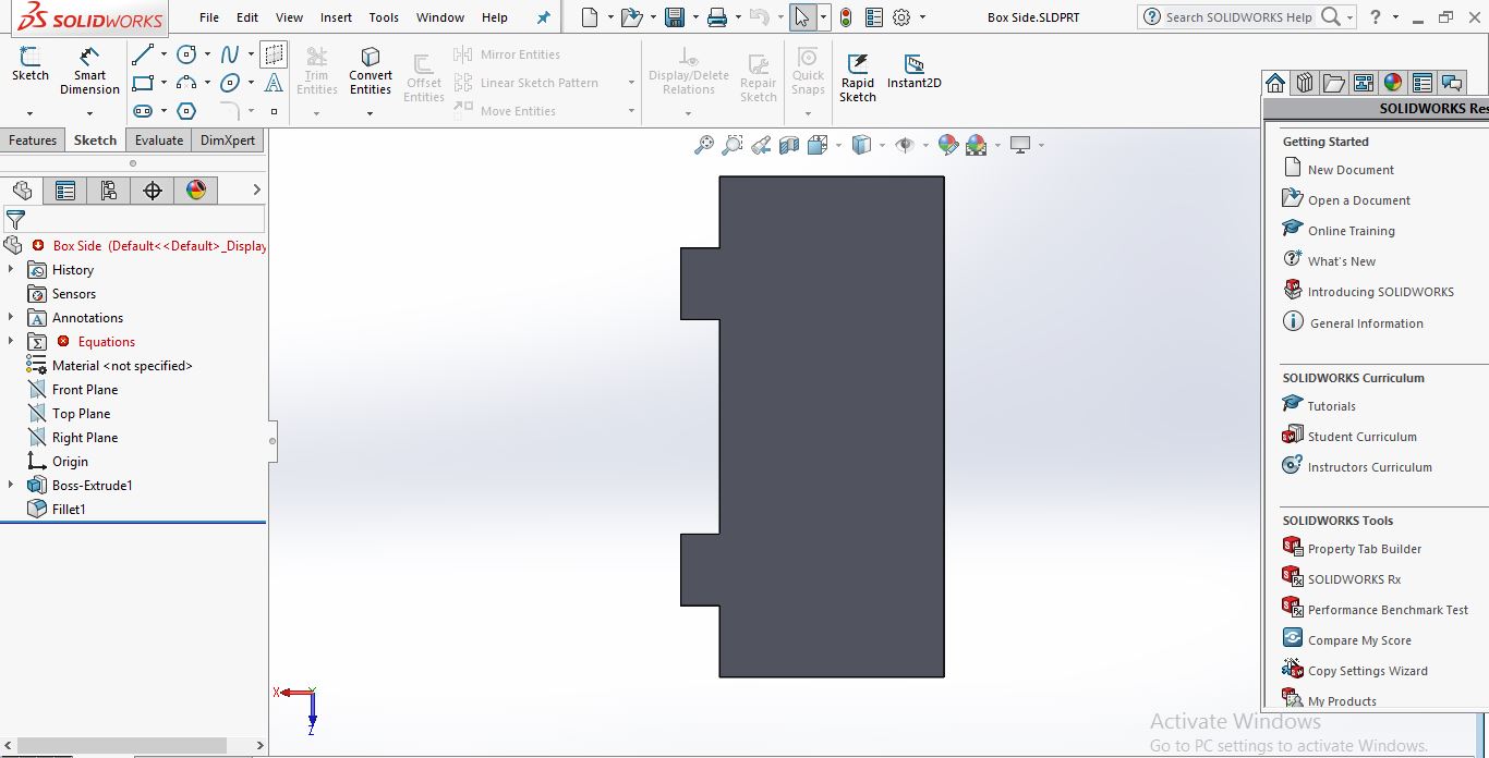
Designing the Base Part 1:
The design needs to be exact anc accurate, so in the starting I spent some time on deciding what the dimensions should be , and the arrangement of the rectangular holes, so that the LEDS can be placed beneath it properly . After making a few designs, I was able to make the complete design. Following are the steps along with illustrations of how I made the base parts.
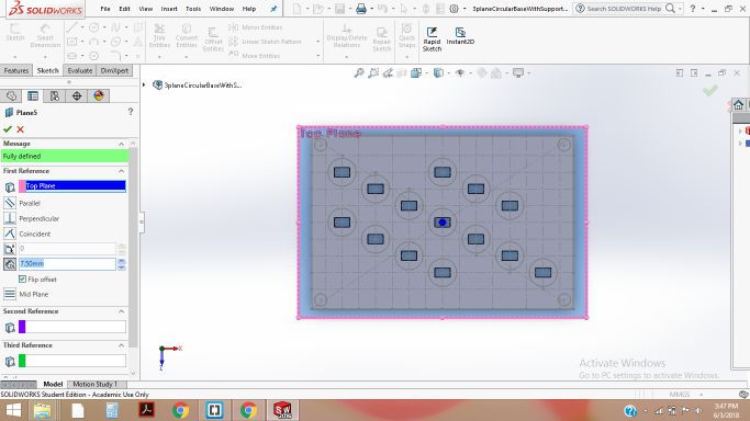
-
I made 3 planes at different heights, and on the first plane I drew the cirlces of 9mm by 9mm as per the footprint of WS2812B leds.
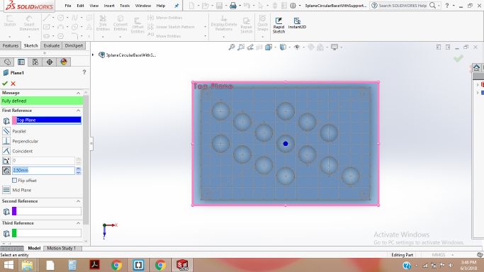
Plane 1 showing the circular arrangement for leds
-
On the second plane, I drew the rectangles of 5mm by 5mm for the square part og RGB leds, having the actual module inside it, thats WS2811 IC.
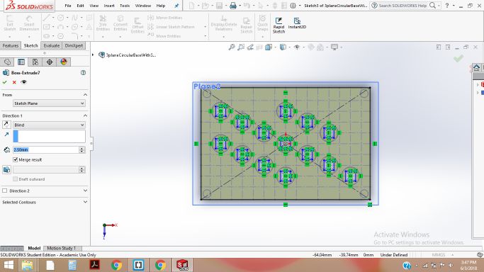
Plane 2 showing the 5mm by 5mm rectangular spaces for leds
-
Using the Cut extrude comand, I made the space for LEDs on the initial plane.

First part of base showing the circular arrangemnt after cut extrude
-
On the third plane, I made the rectangle of 5mm by 3mm , because my acrylic is of 3mm width, and I need to fix the acrlics on this plane.Using Extrude Cut again, I made the cuts.
Arrangmenet for fixing Acrylics right on the top of LEDS placed beneath the base
-
Below is given the arrangement of all the Planes drawn one above the ohter.
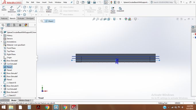
Planes drawn in the solidworks design
-
I needed to draw somwthing which holds the acrylic tight in its place , from the side corners, so for that, I made the following part and made the side slits .
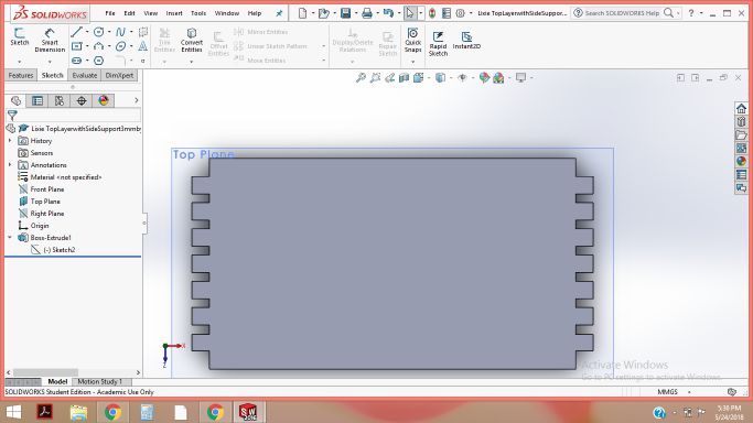
Side slits for holding the acrylic sheets
-
The base design was ready, and it looks pretty good for placing the acrlics on the place and for holding firmly.
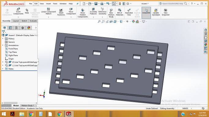
Base is ready for 3D prinitng
-
In the next step, I saved the solidpart file as .STL so that I can generate its GCODE file in cura software for 3D printing.
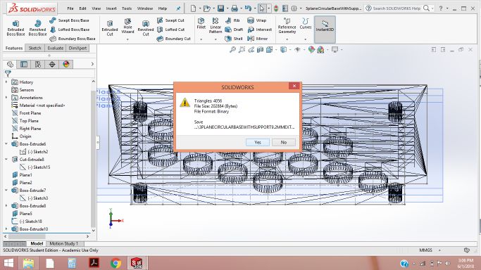
Making the stl file of base
- Then I made the other base part for keeping the main microcontroller board, as discussed in the lectronics part.
- Now, its time to print all the base and top parts , the following files show the GCODE generation in the Cura for 3D printing.
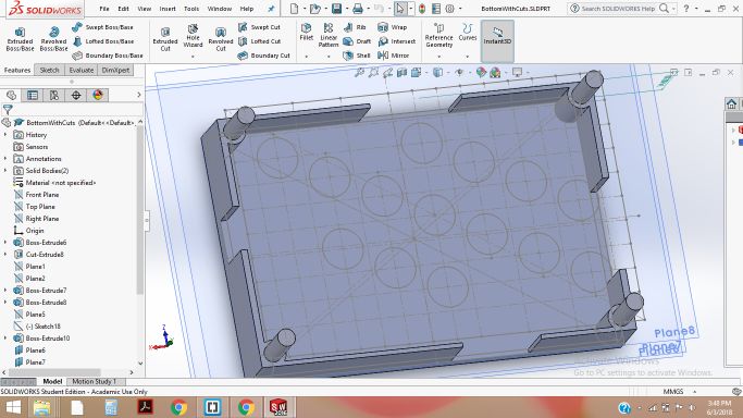
Another part of Base for Lixie digit
.jpg)
Part 1 of base for Prinitng
.jpg)
Part 2 of base for Prinitng
.jpg)
Top of the Lixie Digit for holding the Acrylic and for better glow of leds
3D Printing
The 3D printed parts were not perfect in the first trial, so I tried 2 to 3 times. Each time , a slight modification was done, like making offsets in the slits ,or circle etc/ After the trials , I finally made the perfect 3d printed parts, as shown below:
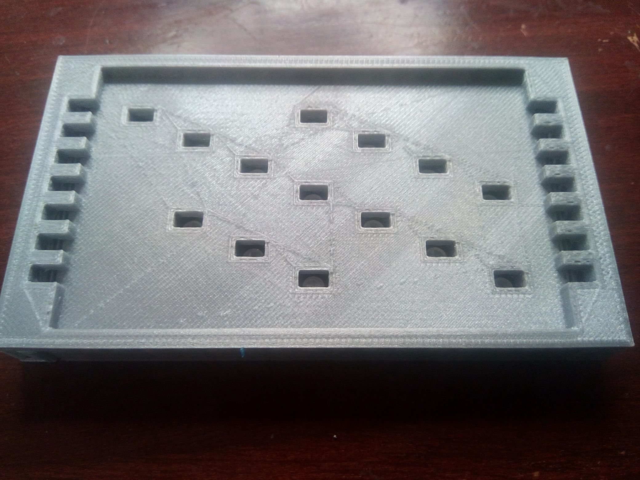
3D printed base part for Lixie digit
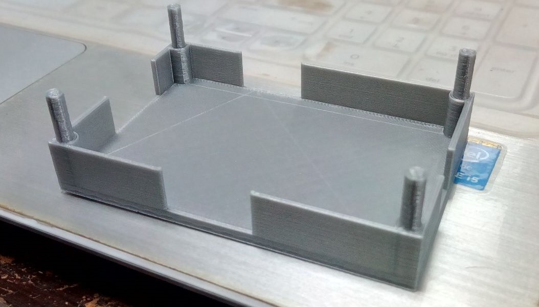
3D printed base part for Lixie digit
Lixie Case Design with Subtractive Manufacturing
Lixies are really intresting and beautiful displays. It, is really necessary to cover them in a proper casing. As part of our final project, one of the important skill to include is Subtractive manufacturing. Initially, I used to think subtractive manufacturing is a process of cutting simply using laser cut or any other cutting machine, but then I get to know more about it , I studied and discussed it with my instructor.
Subtractive machines start with a large block or piece of material, and machine, mill or cut the material until the parts are the size and shape you want. Additive machines start with nothing, and lay down or extrude material to build up the object into the final product. Often, the term Rapid Prototyping is used when describing the technique of building up or adding material to achieve the final “printed” product. The definition is taken from Shopbot

The basic difference between Subtractive and additive technology
Now, I needed to design the case for Lixie, so that it should look simple, but atractive.I also needed to include the subtractive technology in it. I made the following design in solidworks:
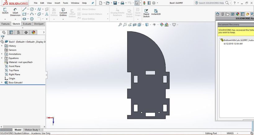
Back part of Lixie Casing
In the bottom part, I drew a pocket as shown below:
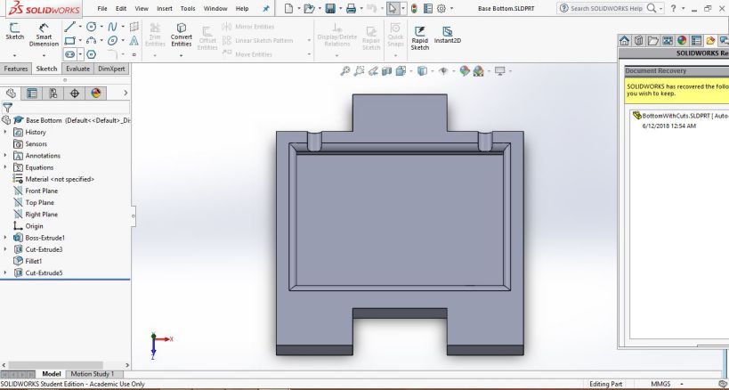
Bottom for Kepping the Base of Lixie
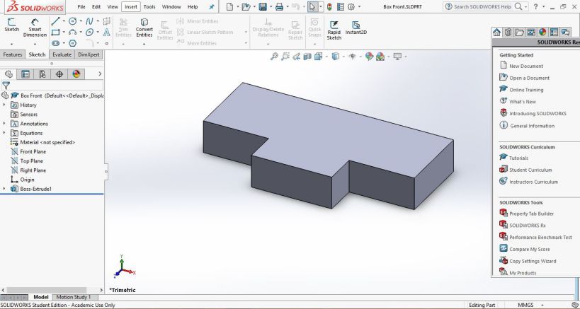
For Covering the Base of Lixie from Front
Side part of Lixie Casing
Assembly of all the parts of Lixie Casing
This CAD modeling is done in solidworks and it is a parametric design , having some basic global variables like Height, width, depth, and material thickness.
Laser Cut
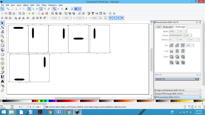
My next task was to cut the Acrylic sheet having segments, and adjusting them into such way so they fit properly in the designed base.For this , I first made the Lixie segments in the inkscape , but then I designed the acrylic in Solid works and saved it as SVG for Laser cut.
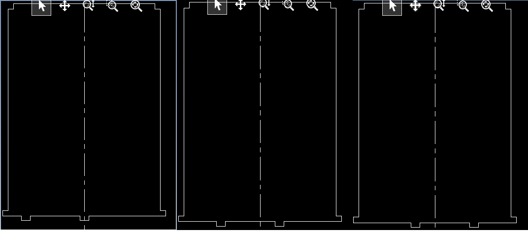
DFX of Lixie segments
3mm transparent Acrylic Laser Cut on Epilog LASER Cut
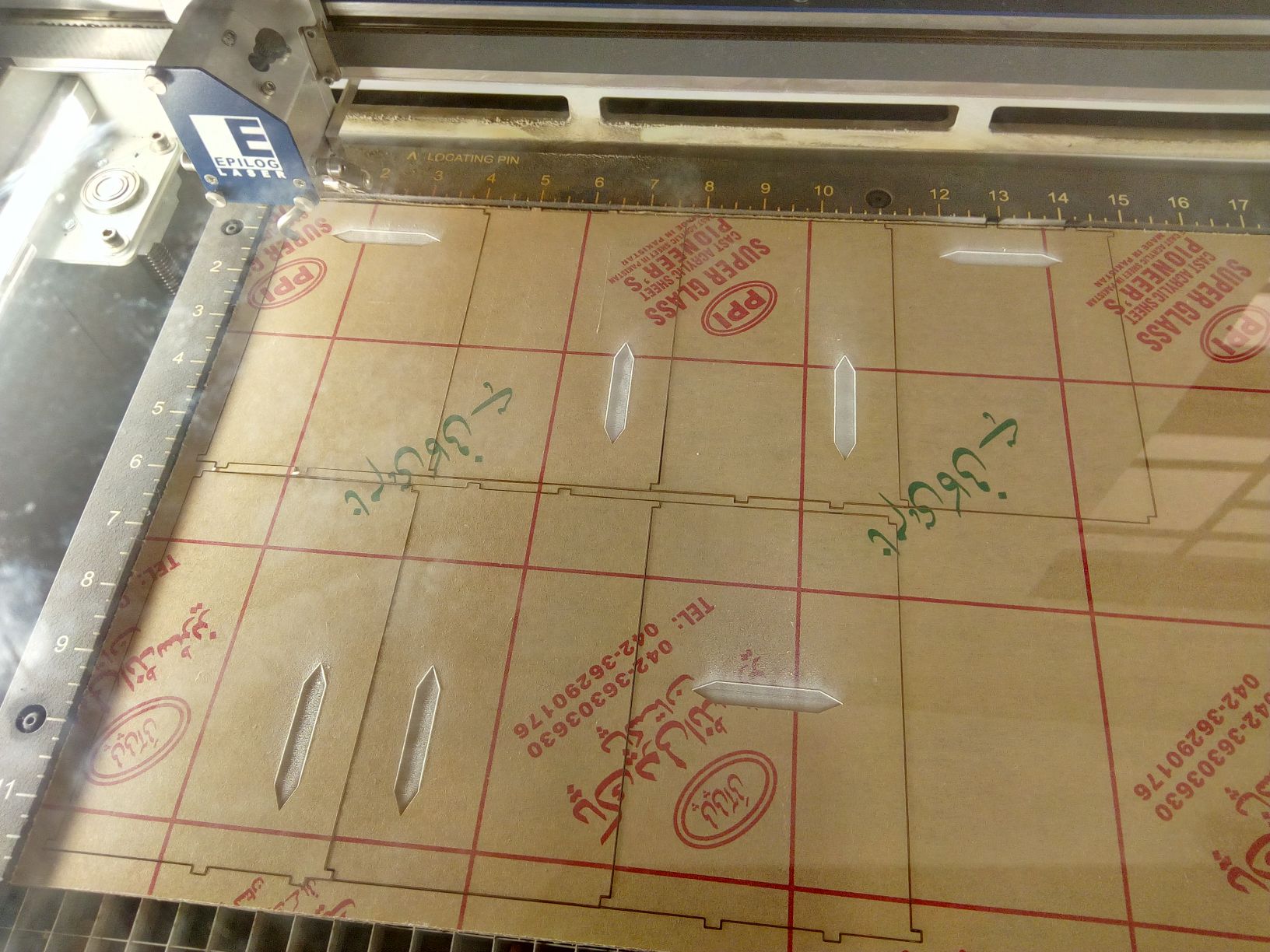
3mm transparent Acrylic Laser Cut on Epilog LASER Cut
Then it was the time to fix the acrylics on base, to see if it fits properly. th laser cut also took 2 trials, and then it was made accurately.
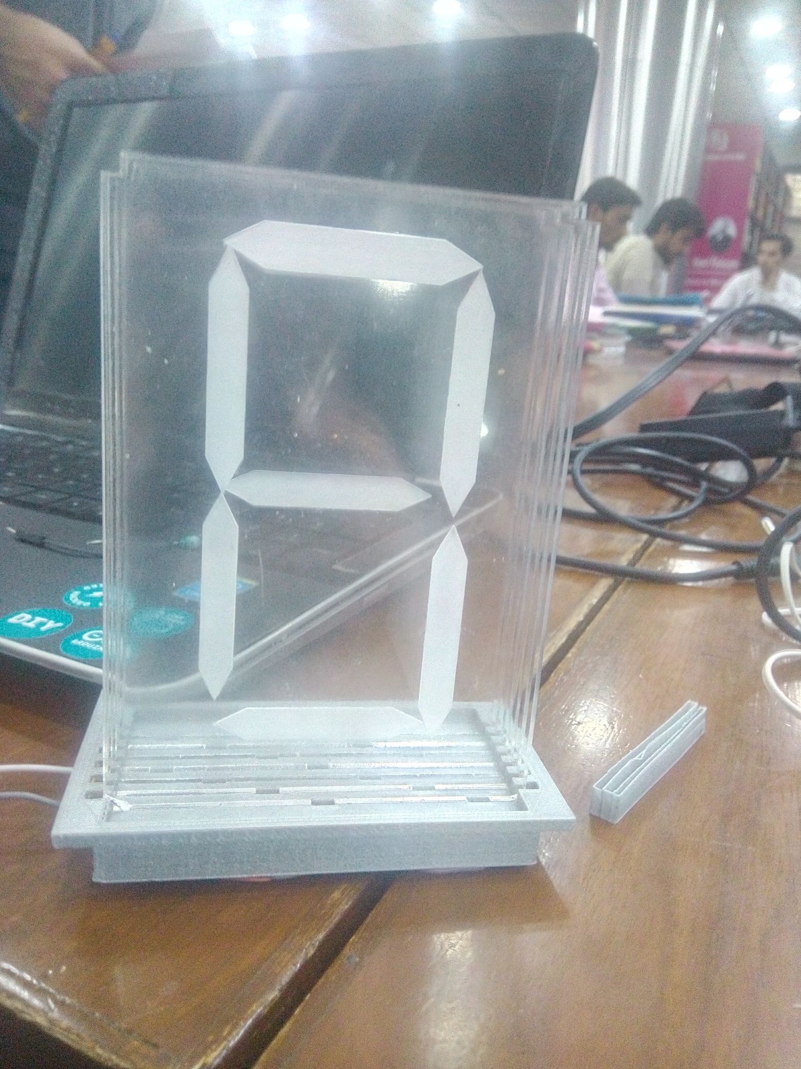
Acrylic sheets fixed in the 3d printed Base
In the same way I made the second Lixie Digit also, as shown below:
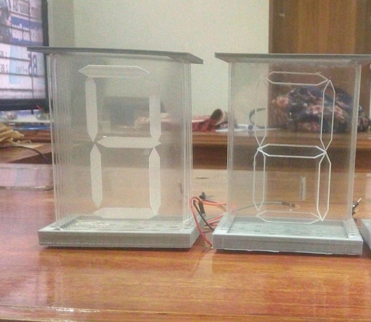
2 Lixie Digits, acrylic cut on Laser Cutter
CNC Lixie Casing
For Cutting the casing for Lixie, I had already made the model in solidworks.The model is based on a modular design, one Lixie can be attached by on the side of 1st Lixie and so on. As described in the case designing part, I need to cut the model on shopbot. We have worked on shopbot during Computer Controlled Cutting. So, the whole process from designing to cutting is described through a video.I had saved the .SLDPRT files of Solidworks as .DXF also, because In Vcarve we import vector files. So, Now the next step is generating toolpaths in Vcarve.
For Cutting the casing for Lixie, I had already made the model in solidworks.The model is based on a modular design, one Lixie can be attached by on the side of 1st Lixie and so on. As described in the case designing part, I need to cut the model on shopbot. We have worked on shopbot during Computer Controlled Cutting. So, the whole process from designing to cutting is described through a video.I had saved the .SLDPRT files of Solidworks as .DXF also, because In Vcarve we import vector files. So, Now the next step is generating toolpaths in Vcarve.
The Following GIF image shows that the toolpath is being gnerated.For further details about generating Vcarve are discussed on my Week08 page.
The GIF image showing Vcarve being generated
Lixie Case Design on Shpbot
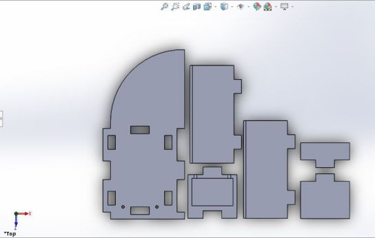
The parts for casign were completed and are shown below, along with the base parts having pockets in it to keep the lixie base.
In the same way I made the second Lixie Digit also, as shown below:

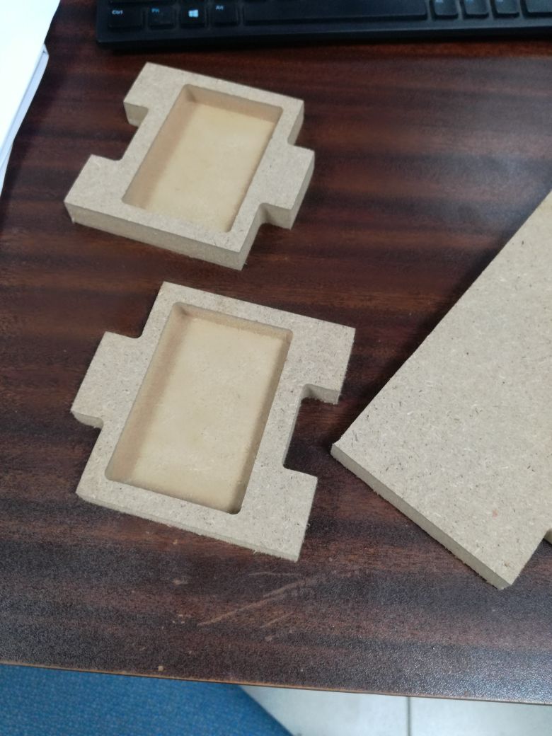
All the parts for casing and Base part
After slight rubbing on each part , I assembled them as shown in the image below:
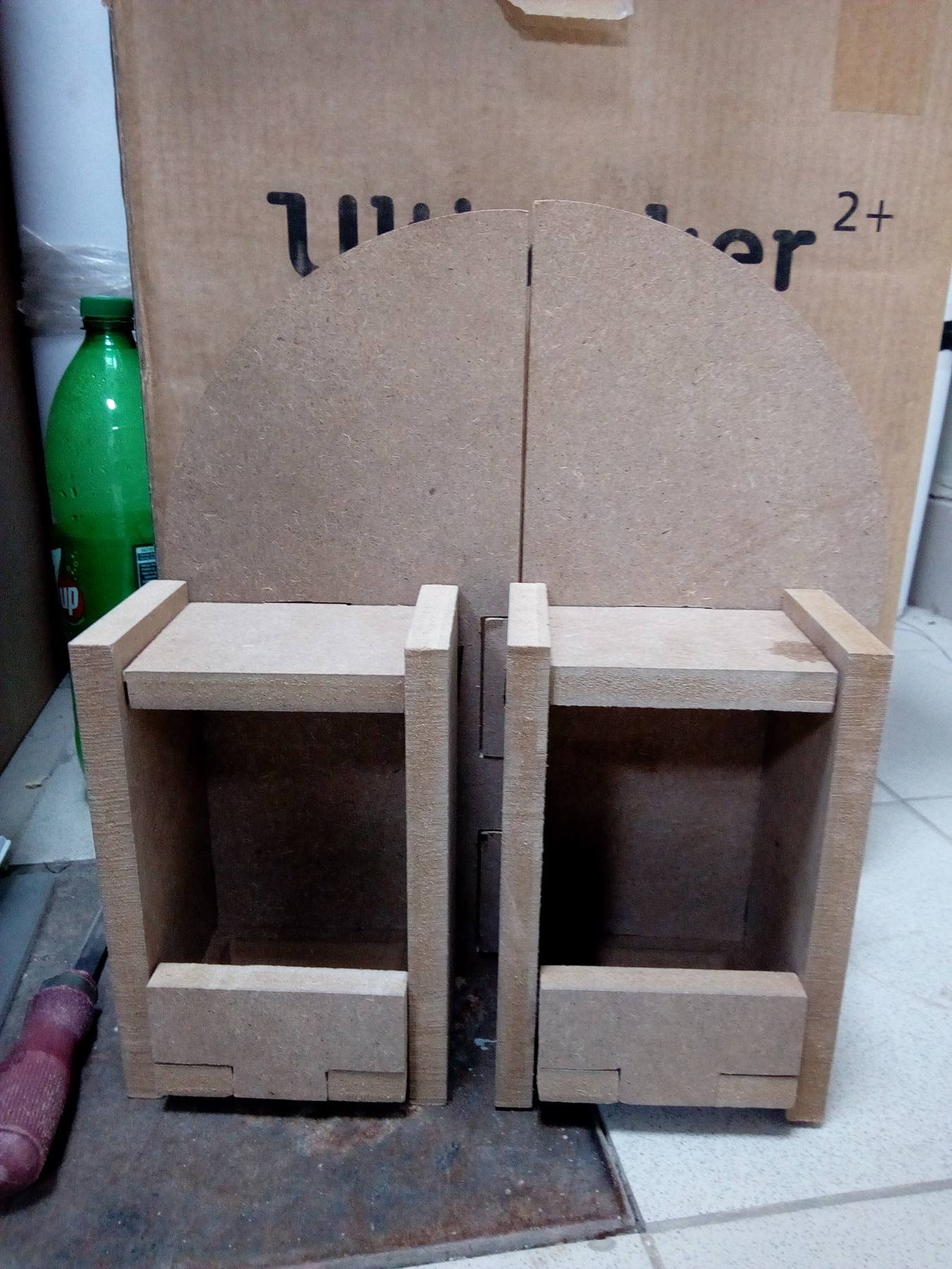
lixie Casing designed in Solidworks and cut by Shopbot
Electronics Production
This part of project took a great time, because the PCB boards that I made using WS2812B LEDs for my Lixie digits were not working properly. Initially I made Lixie PCB for 20 WS2812B RGB Leds having footprint of 5mm by 5mm. All of my trials and experimentation on making the Board are discussed in detail.
Trial 1: Lixie PCB with 20 WS2812B RGB 5mm by 5mm LEDs
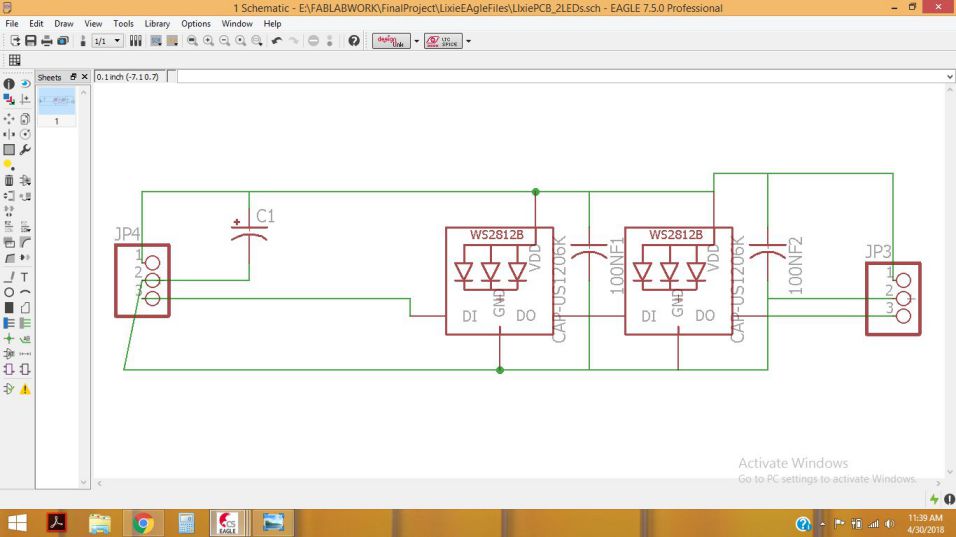
By keeping the Lixie circuit in mind, I made the circuit in Eagle since I have been using this software during the whole fab academy course, and arranged them in a way so that all the acrylic sheets can be placed and stacked together on the top of PCB .
The best thign about WS2812B RGB LEDs is that we can connect as many LEDs as we wish , just by connecting them in a chaqined fashion, The Dout of LED1 --> connect to the Din of LED2 and so on. The chained arrangement is shown clearly in the schematic digram and the board given below:
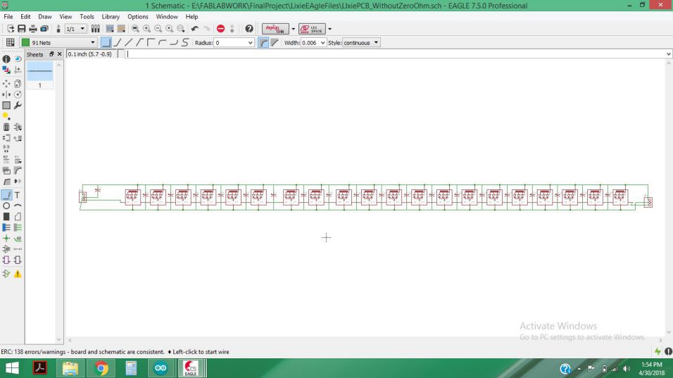
The schematic diagram for LEds connected in chained fashion
After checking the ERC (Error check ) , I performed the routing for my 1st- version of Lixie.
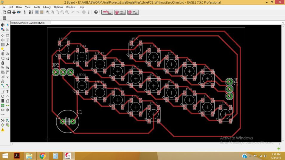
the PCB board is ready for printing
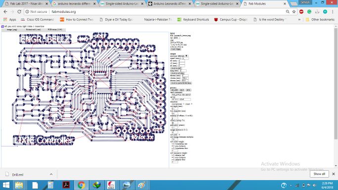
By exporting the Image as .PNG , I made the files for TRaces, Drill and outline, so that I can generate .RML from the .PNG files.
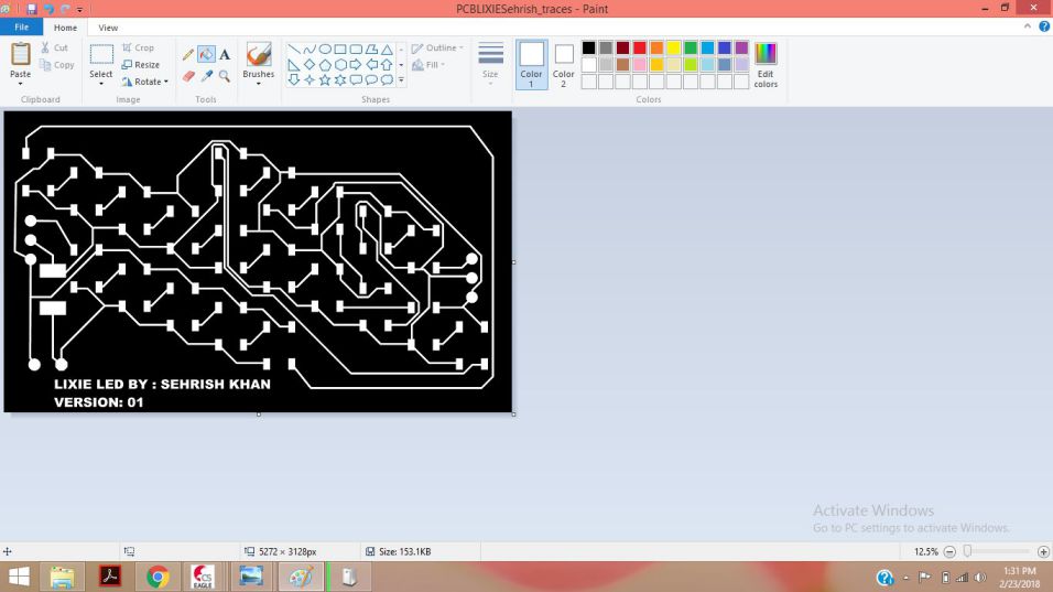
Editing the .PNG of PCB Board in paint
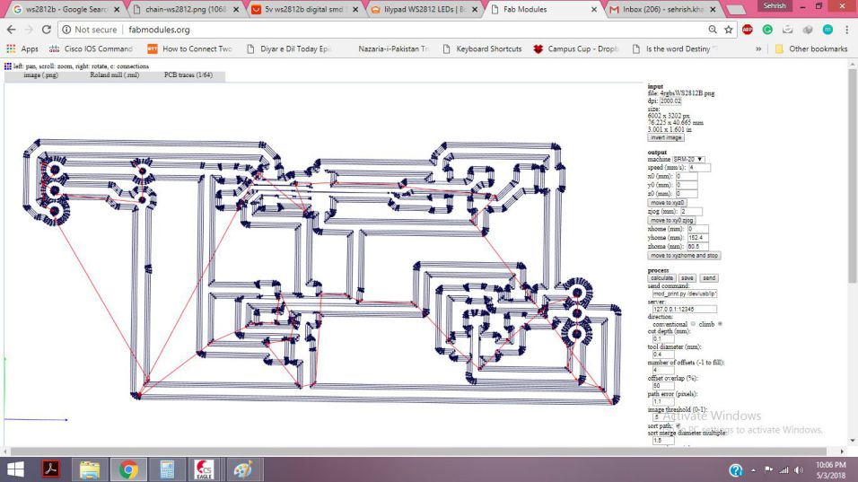
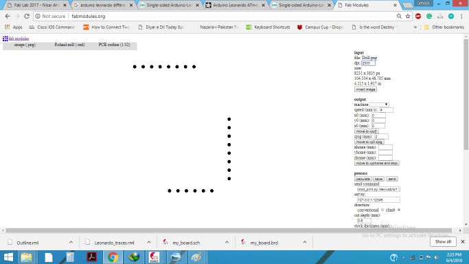
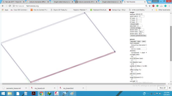
As we know that we need to generate .RML files for milling on Rolland SRM-20. So, I generated the .RML files in fabmodules.org as given below:
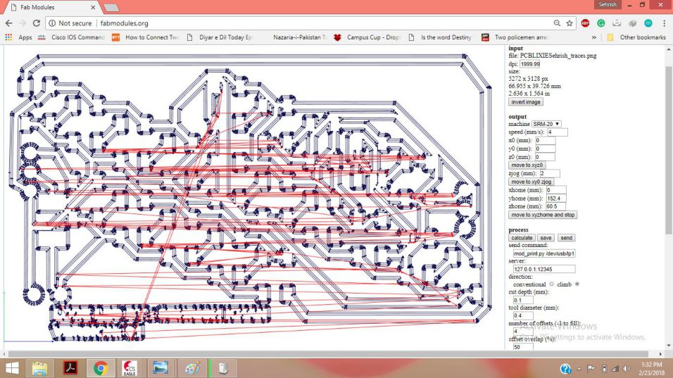
RML for Traces of PCB board is generated
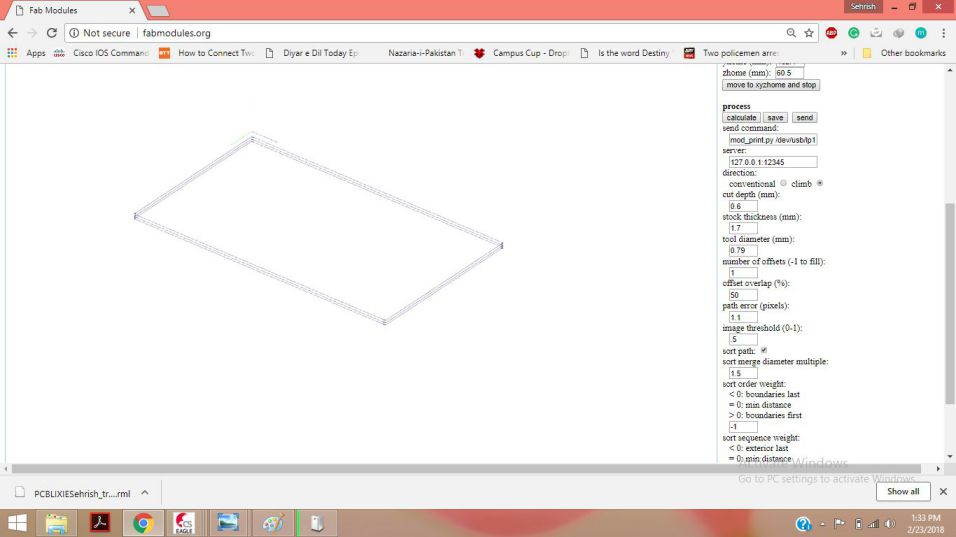
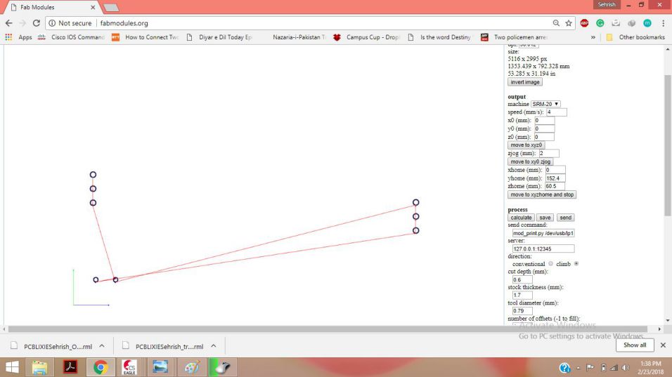
RML for Outline and Drills of PCB board are generated
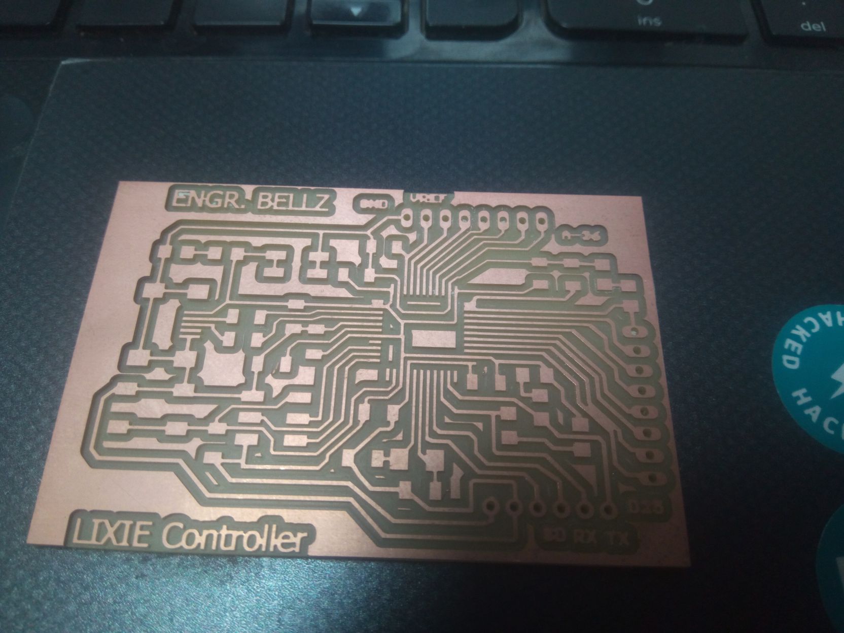
The board was milled successfully as shown below:
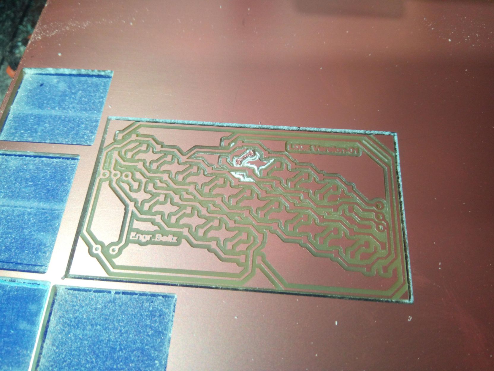
The board After Milling
Soldering the WS2812B was really a challenging task, as the pads for the soldering have very little surface, so initially I tried to solder a few LEDs and then I soldered the LEDs on the board:
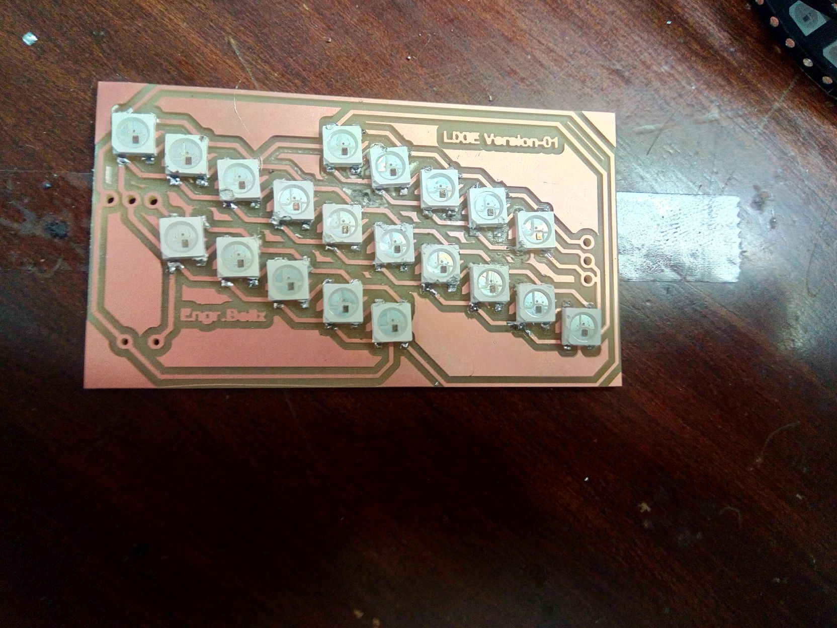
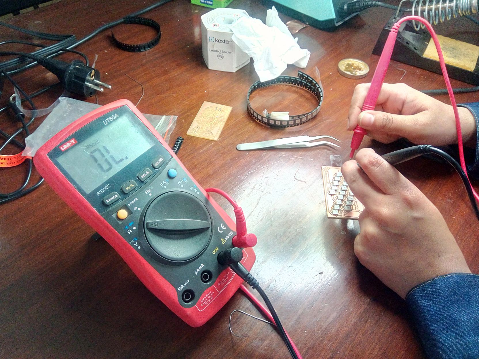
Soldering and Testing the board of Lixie - Version 01
Failure 01:
All was fine, from the circuit designed to the milling and soldering of board, even while testing i was getting output voltage at every led, but when I programmed the LEDs with FastLED.h and then Adafruit Neopixel LibraryI was not getting the desired results.The Leds were not being addressed proeprly, the Data was not being latched fro one LED to the other.
Trial 2: Lixie PCB with 2 WS2812B RGB 5mm by 5mm LEDs
During my global review , I showed the Lixie PCB board to Prof.Niel , and he suggested me to make 2 RGB LEDs PCB board first , and then try for large number of PCBs.He admired me for choosing this final Project and he liked the idea of making the
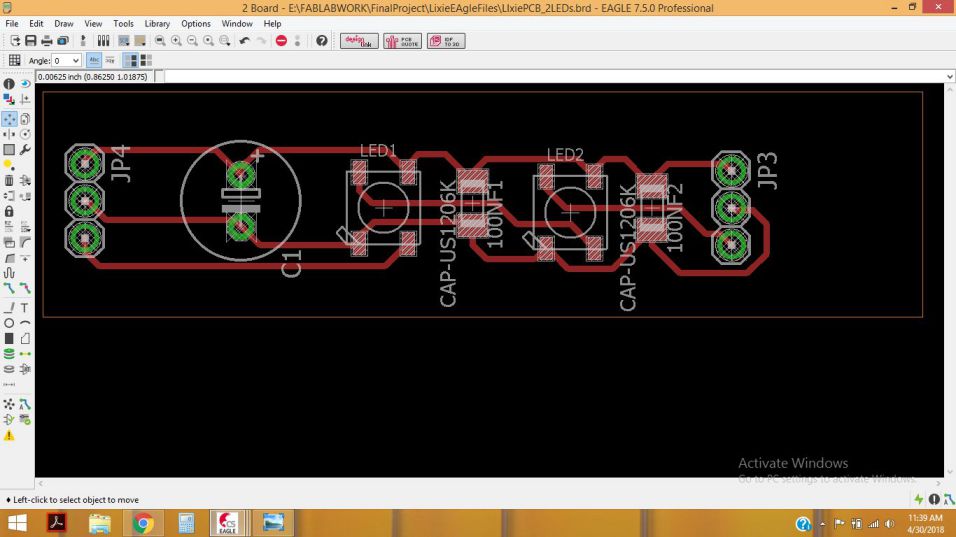
Schematic and board for 2 WS28812B RGB LEDs
After genrating the RML files, I milled the board, and then soldered it. For testing purpose I programmed it with arduino, the code and result is shown below:
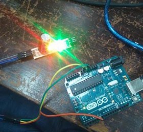
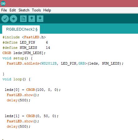
The two WS2812B leds glow with the given code
Trial 3: Lixie PCB with 4 WS2812B RGB 5mm by 5mm LEDs and 100uF Capacitors
After glowing the two LEDs, I researched a lot about the problems in these RGB LEDs, almost on all forums it was written that timing is really critical issue in these LEDs, and the distance from one LED to the other also matters. So, I though to give it another try to check and anykyse the issues closely. The scematic and Board images are given below:
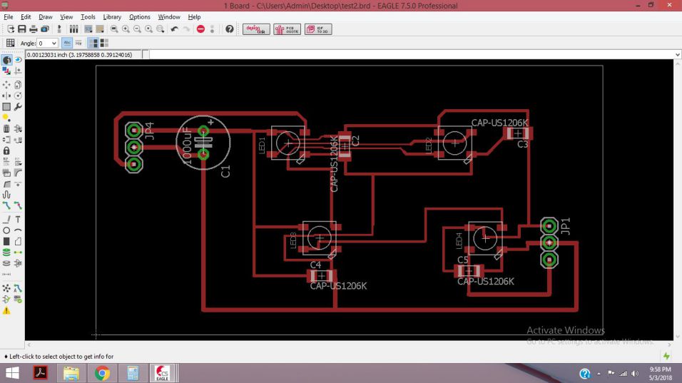
PCB board for 4 WS28812B RGB LEDs in Eagle and its RML being generated in fabmodules
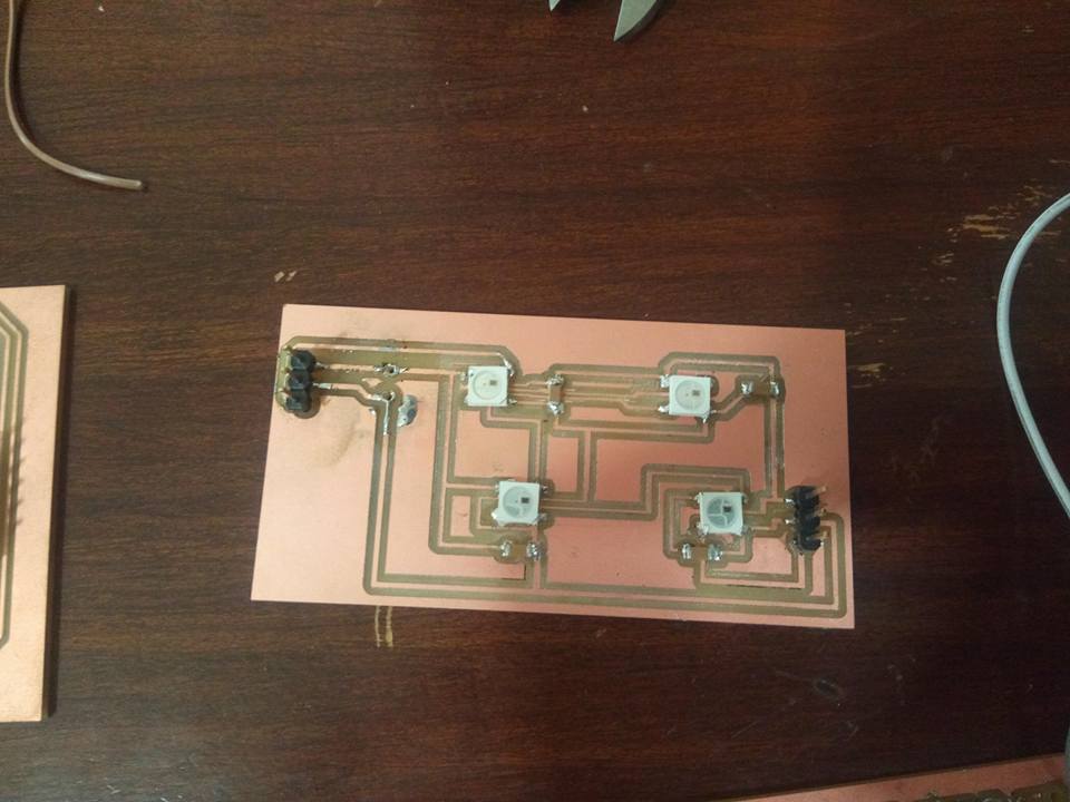
Four WS2812B leds
Due to the large distance between leds, I did not get the desired result, but then I searched more about the possible issues and ways to make LEDs work.
Trial 4: Lixie PCB with 20 WS2812B RGB 5mm by 5mm LEDs and 100uF Capacitors
This time I ws quite sure that if I add a capacitor at the VCC and GND of each led, then it wll work fine, So I interfaced it with Attiny44 microcontroller. I really studied a lot about it , and then made the following design:
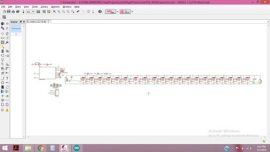
The schematic diagram for WS2812B LEds with ATTiny44 and 100uF Capacitor
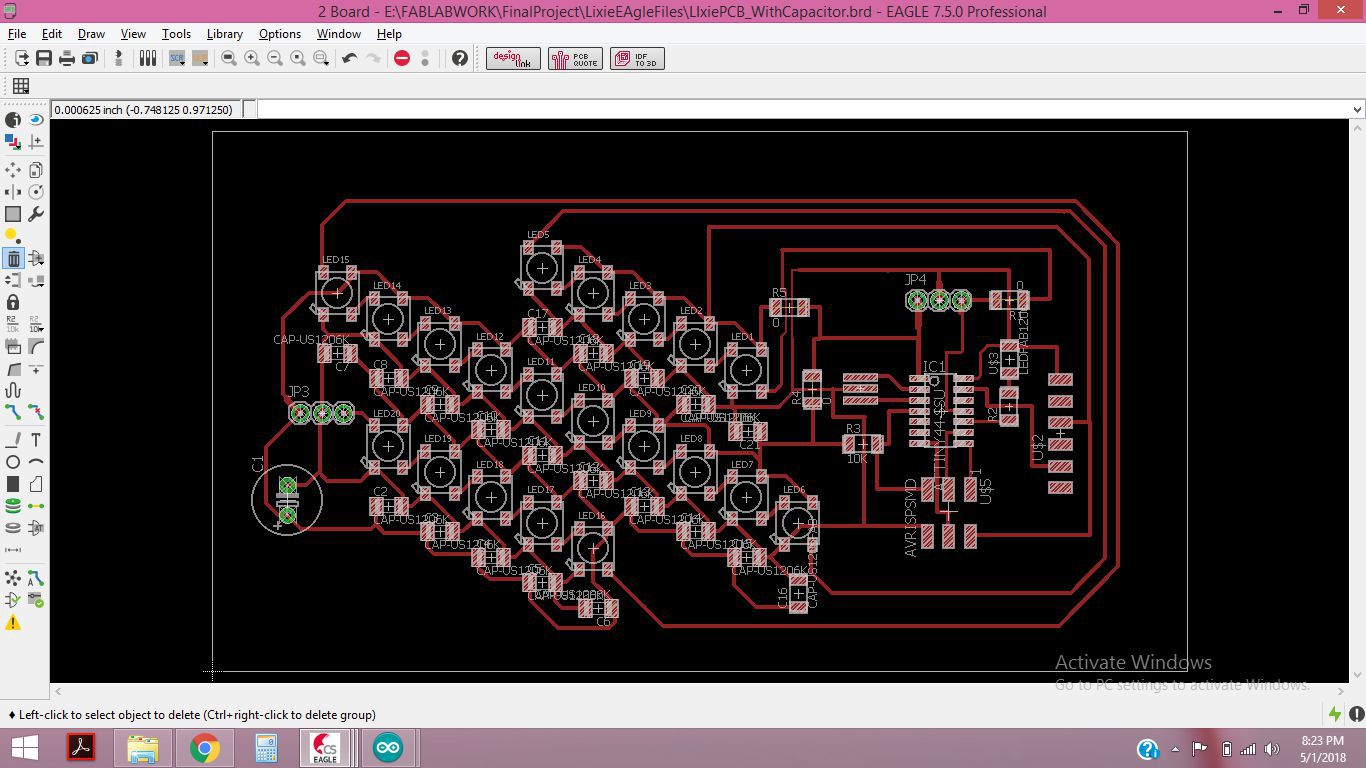
The PCB board for WS2812B LEds with ATTiny44 and 100uF Capacitor
After gnerating the RML files, I milled the board
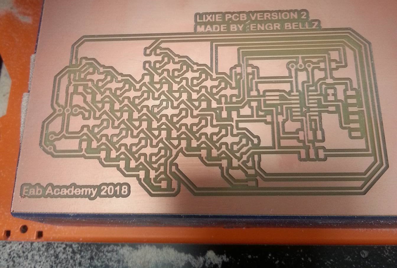
The PCB board for Lixie VErsion 2
This time I wqs quick at soldering, and then I noticed that I had made a mistake and didnot connect the Din to the pin of microcontroller, so for testing purpose I connect it manually.
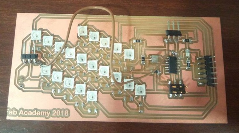
The PCB board of Lixie Version 02 for WS2812B LEds with ATTiny44 and 100uF Capacitor
After finishing the soldering I burnt the Bootloader in ATtiny44 using my FabISP.Then, I tried glowing the 20 leds with FastLEd and Neopixel library.
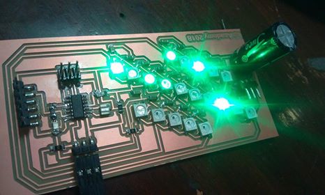
The Output is again disappointing, LEDs are glowing randomly
Miroad 100pcs WS2812B 5050 Addressable SMD Smart rgb led :The solution to my problems of Lixie PCB
After spending a lot of time on trials and experimentation, I needed a quick solution since I was running out of time. I had many modules left to complete, but I was quite sure that I will complete the remaining tasks once I get the WS2812RGB LEDs functioning properly. While searching for this project I found some alternatives to this problem, and the easiest solution to me was using the WS2812B 5050 Addressable SMD Smart rgb led . These are exactly the same RGB leds that I was using, and of the same dimension. The advantage of using these LEDs was that I can connect them with wires to connect one led to other and so on.
Neopixels (WS2812B RGB LEDs)
Testing WS2812B RGB LEDs
I connected 8 LEDs to test, and they were working fine, I was able to address all the leds individually.
Neopixels (WS2812B RGB LEDs) testing
Then, I checked the acrylics with numbers engraved on it, to see how the LEDs glow will appear on the segments that I will be designing later.
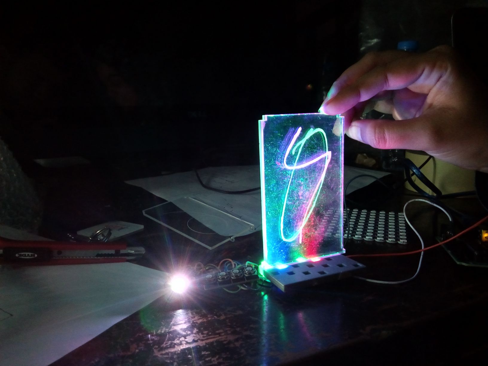
Neopixels (WS2812B RGB LEDs) testing on acrylic
Soldering the LEDs for fixing in base
I had already designed the Base for Lixie digits, now after testing the LEDs, I was able to move further. After 3D printing the Lixie Base, I connected the LEDs with wires and soldered them. Then I fixed the LEds base.
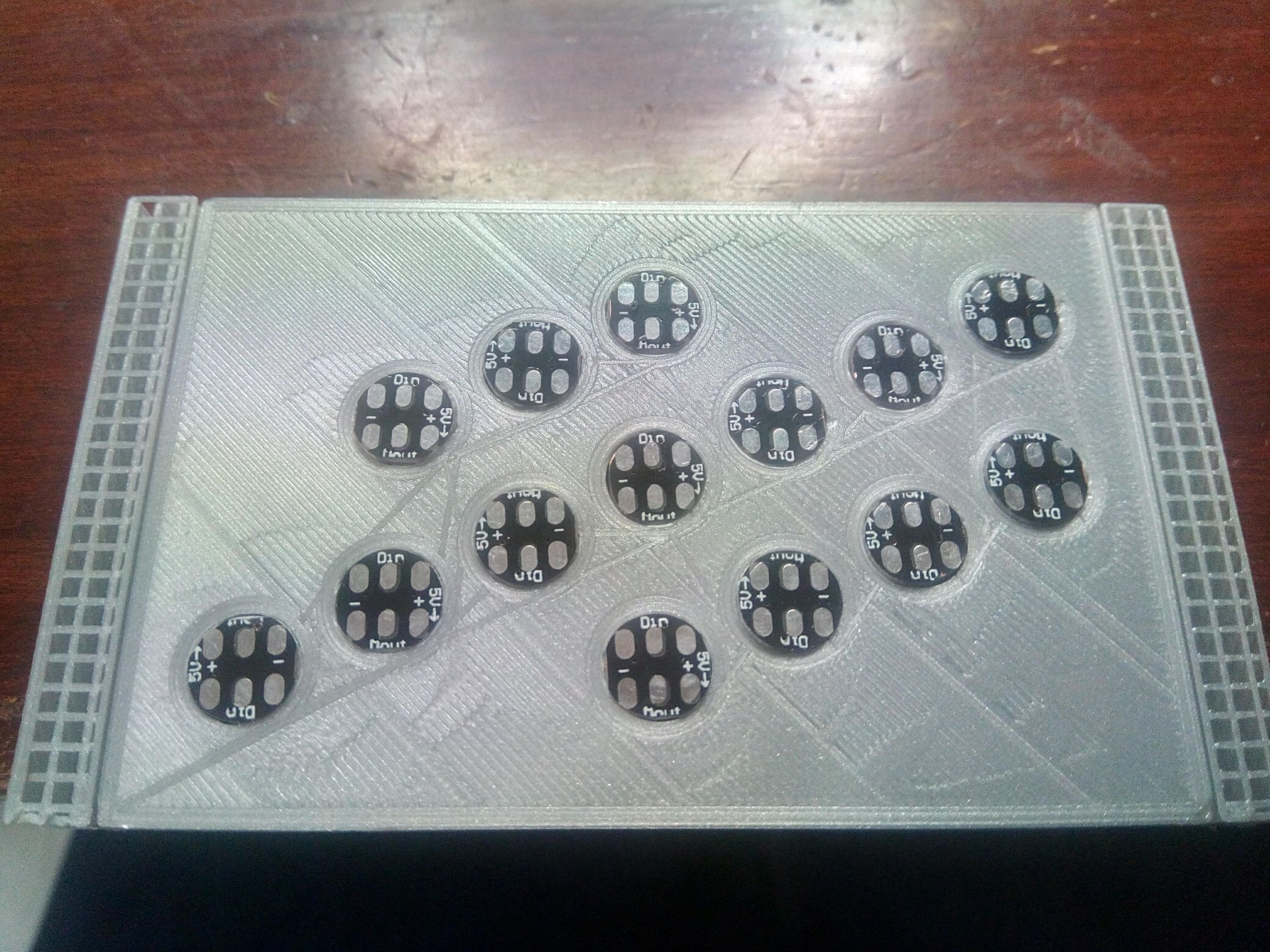
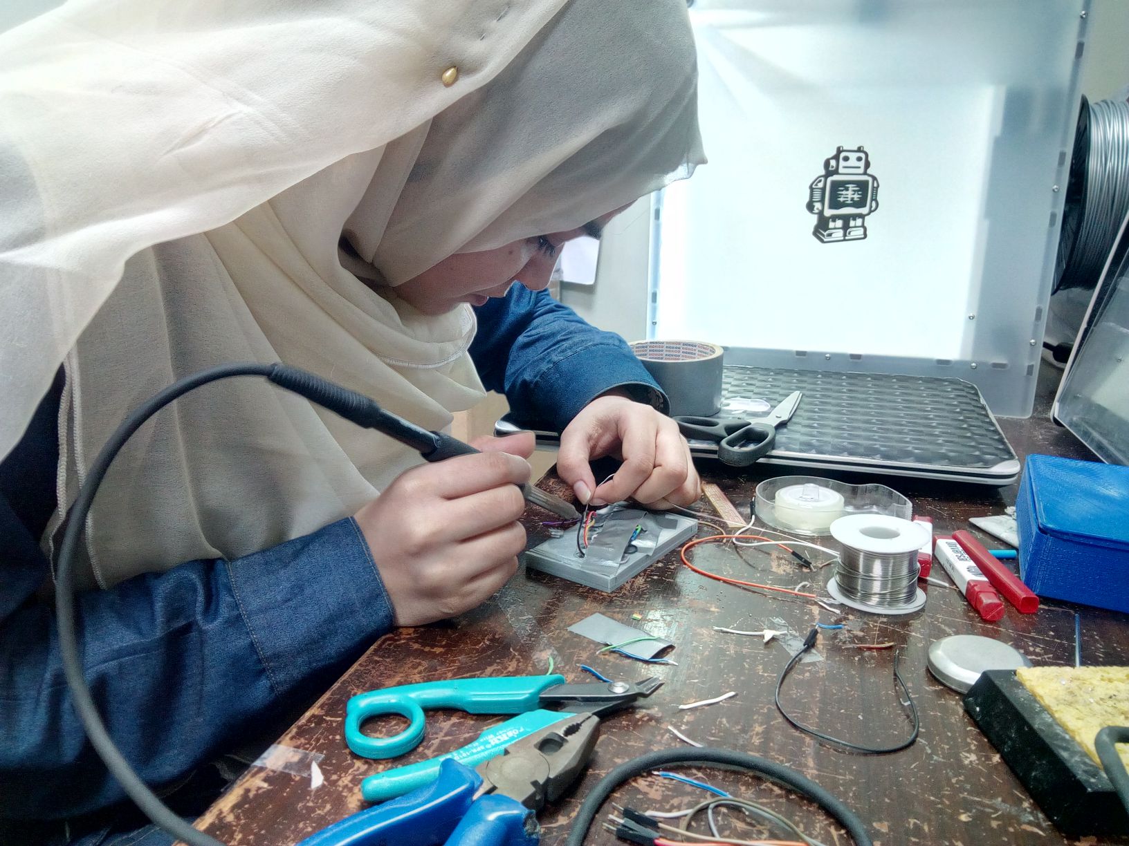
Neopixels (WS2812B RGB LEDs) fixed in the base and while soldering
Afer soldering and connecting the wires, I tested the LEDs on Ardunino, because I had not designed the Arduino Leonardo yet.The LEDS were glowing very well and I was able to check different codes with Fastled.h and Adafruit Neopixelslibraries.
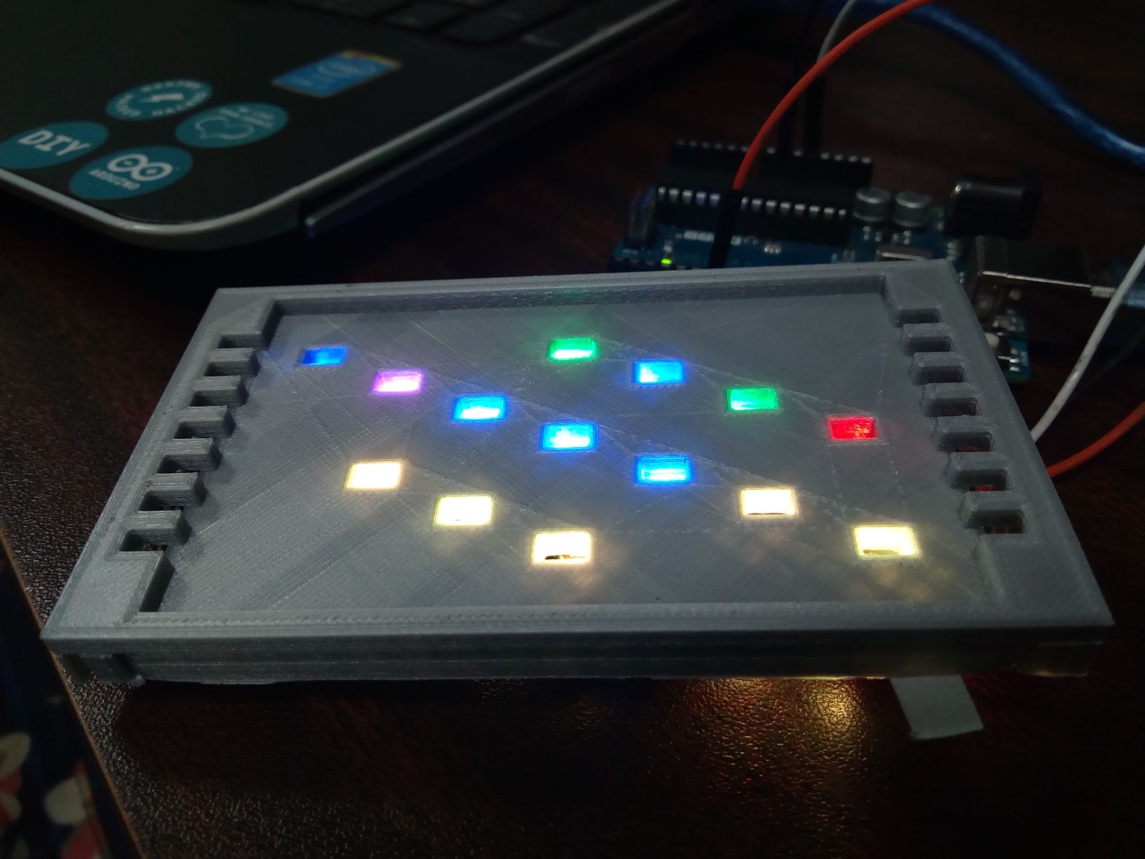
Neopixels (WS2812B RGB LEDs) on the Lixie Base
Making the Arduino Leonardo Board
Now, I moved to the next step of designing the Arduino Leonardo board. Each RGB WS2812B LED requires 60mA of current (20mA for each red,green and blue).The Arduino Leonardo board has ATmega32U4 microcontroller and after reading its (Datasheet) I came to know about important characteristics and things to be considered while desiging.
- It is an 8-bit AVR RISC-based low power microcontroller chip
- It has 32KB self-programming flash program memory
- It has 2.5KB SRAM, 1KB EEPROM
- It is based on USB 2.0 full-speed/low speed device , hence making it suitable for low power
- It has 12-channel 10-bit A/D-converter and JTAG interface for on-chip-debug
- The device achieves up to 16 MIPS throughput at 16 MHz. 2.7 - 5.5 Volt operation.
- Crystal-less operation for Low Speed mode
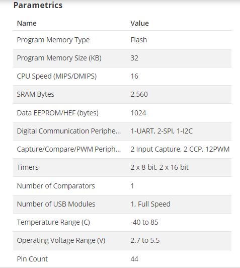
Arduino Leonardo parameters
After searching for some layouts ,and made the schematic and board in Eagle.
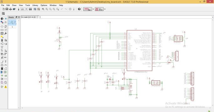
Schematic of Arduino Leonardo board in Arduino
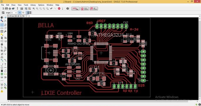
Arduino Leonardo board in Eagle
After completing the Lixie Files, I generated RML from the .PNG images.
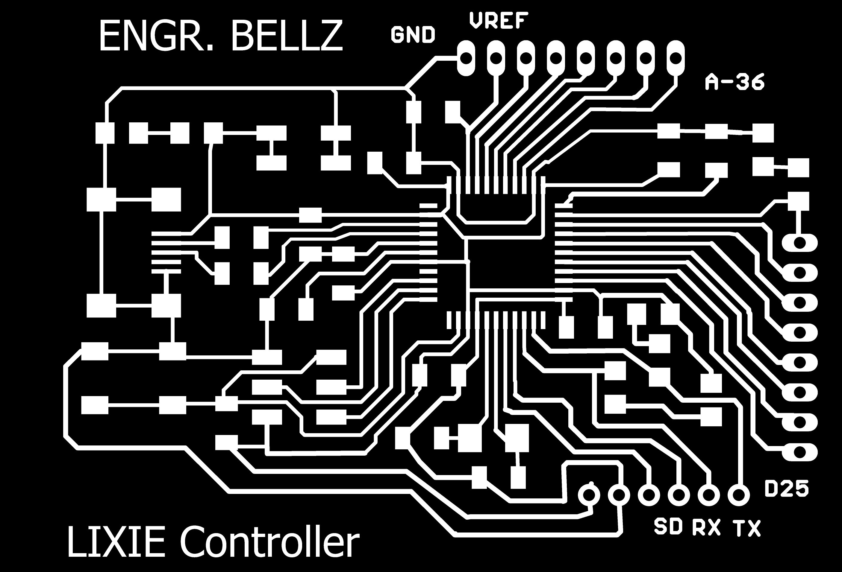
Arduino Leonardo editing in paint


Drill and Outline PNG files
For milling I need .RML files , which we can generate using FabModules
Arduino Leonardo Traces RML
Arduino Leonardo Drill and Outline RML
The next step is milling the board on Rolland SRM-20 milling machine, for traces we use 1/64 tool and for drills and outline, we use 1/32 tool size.
Arduino Leonardo board after Milling
Now, I need to solder the components, and for that first I made the list of required components. Then , while soldering it was really important to solder the ATmega32U4 IC in a proper manner. I have never soldered this IC before , but with care I did the soldering. After soldering I got some issue while burning the bootloader , and as expected it was soldering issue.So, after fixing the soldering issue I burned the bootloader successfull.
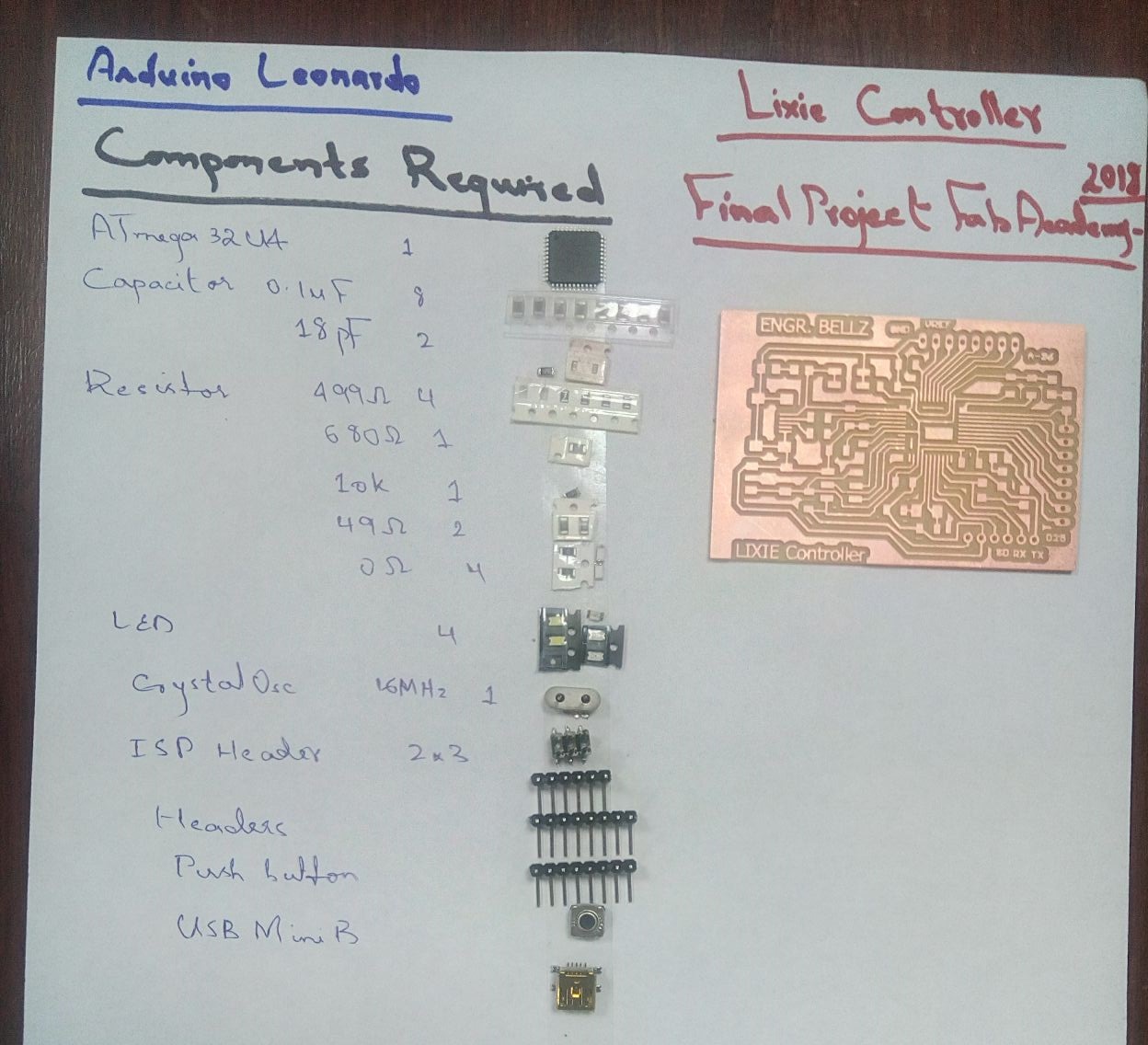
Arduino Leonardo list of components
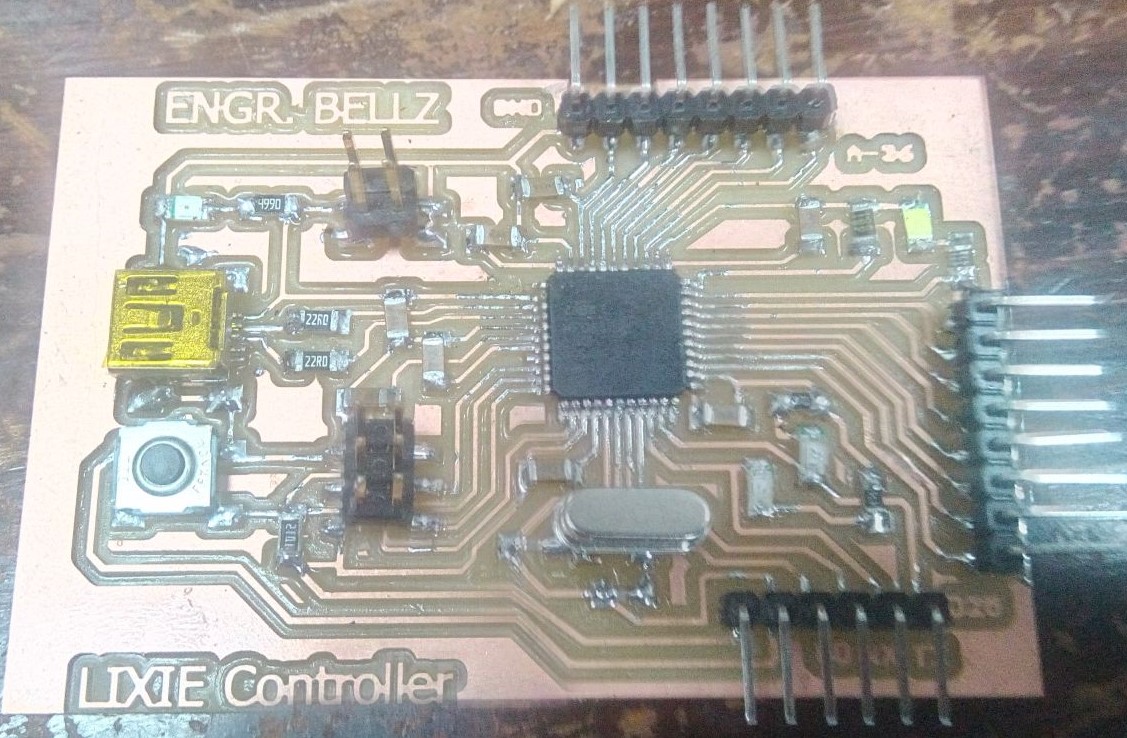
Arduino Leonardo with ATmega32U4
Programming for Lixie
The programming of Lixie is based on Arduino IDE , as it is simple, easy and have multiple libraries. The two libraries that i used for programming the lixie digits are FastLEd.h and Adafruit Neopixel library.
Glowing All LEDs:
All you need to know about using FastLed is avialable here on GitHub There were several test codes available , so First I simply tried to glow all the leds by using the following program.
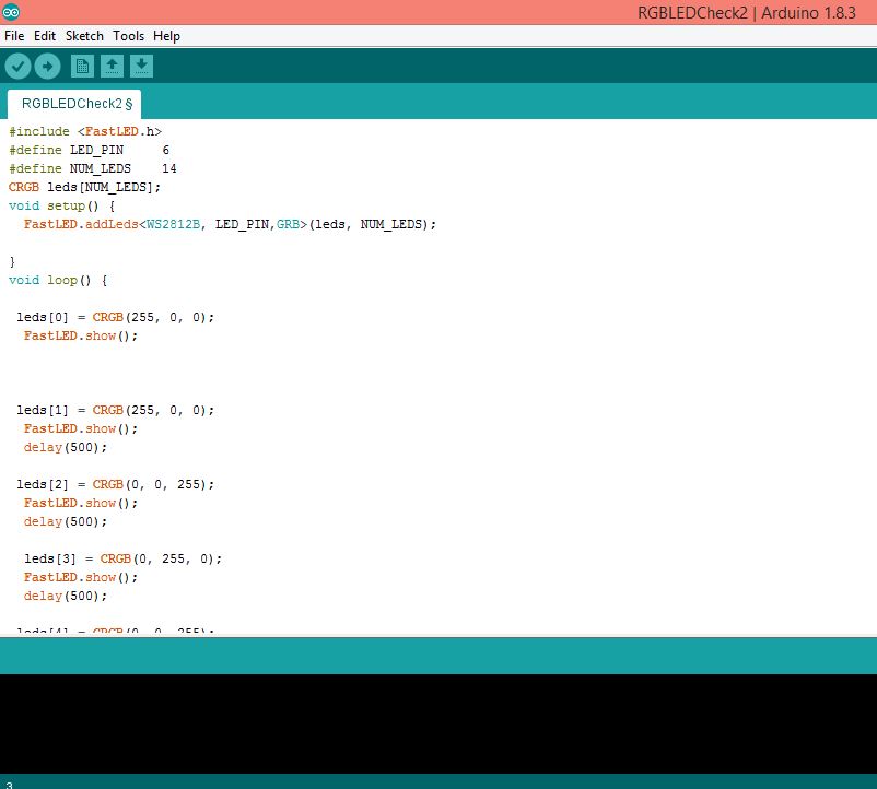
Testing the FastLed on Lixie with WS2812B RGB LEDs
I tested the code on the First Lixie Digit, and it glows like this
Rsult of the FastLed on Lixie with WS2812B RGB LEDs
Lixie displaying Counter from 0 to 9
Then, I made a program to glow the numbers from 0 to 9 on the segments, just like we do with a counter.So, for this I used the same FastLed library , and put the code in a switch case. I made the sequence of Leds needed to be glowed for a partivular number. The full code is attached at the end of documentation.
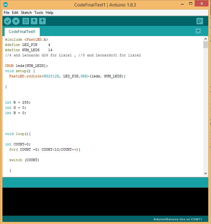
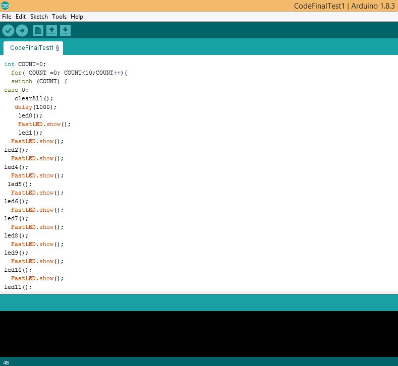
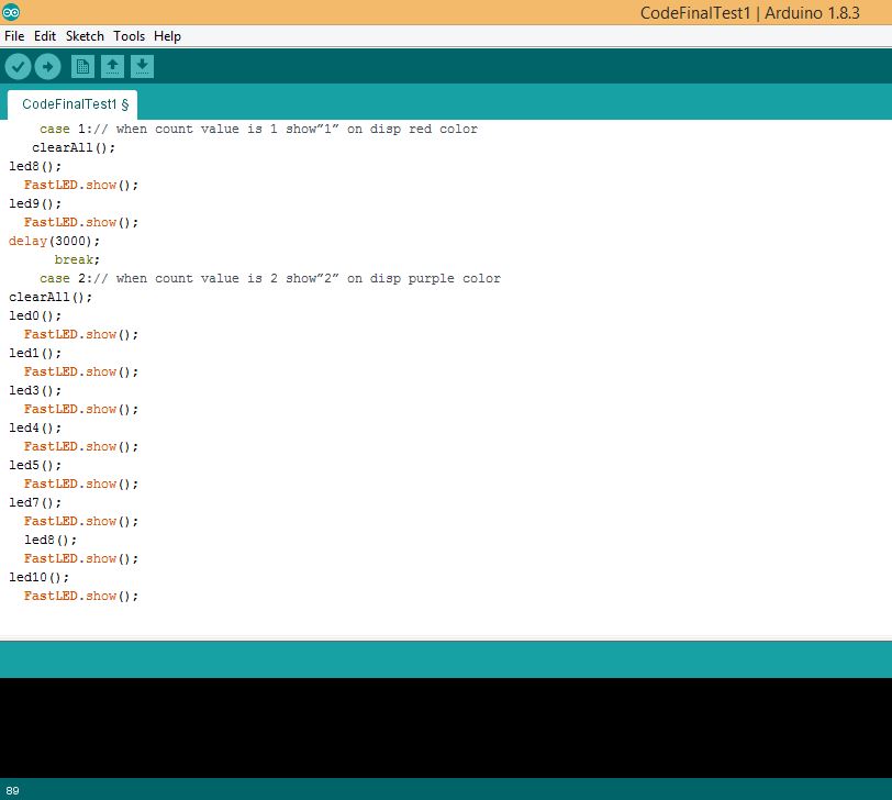
Program for counter using switch case with the FastLed for WS2812B RGB LEDs
Results Obtained
Now, its time to test the codes I have written so far . First, I tested the code I made with switch case and made a sequence for different numbers to be displayed on the digits. The Full codes are attached at the end of documentation.
Lixie Digit 1 Showing the counter from 0 to 9
For the second Lixie, I tried to make segment by outline rather than complete engraving of the segment. I got nice glow this time also.
Lixie Digit 2 Showing the counter from 0 to 9 on the outlined segmented Display
Lixie In Casing
I had made ready the Casing for Lixie , and its design and cutting on shopbot is discussed already. Now, its time to put the Lixies in casing , wire it and then test it.
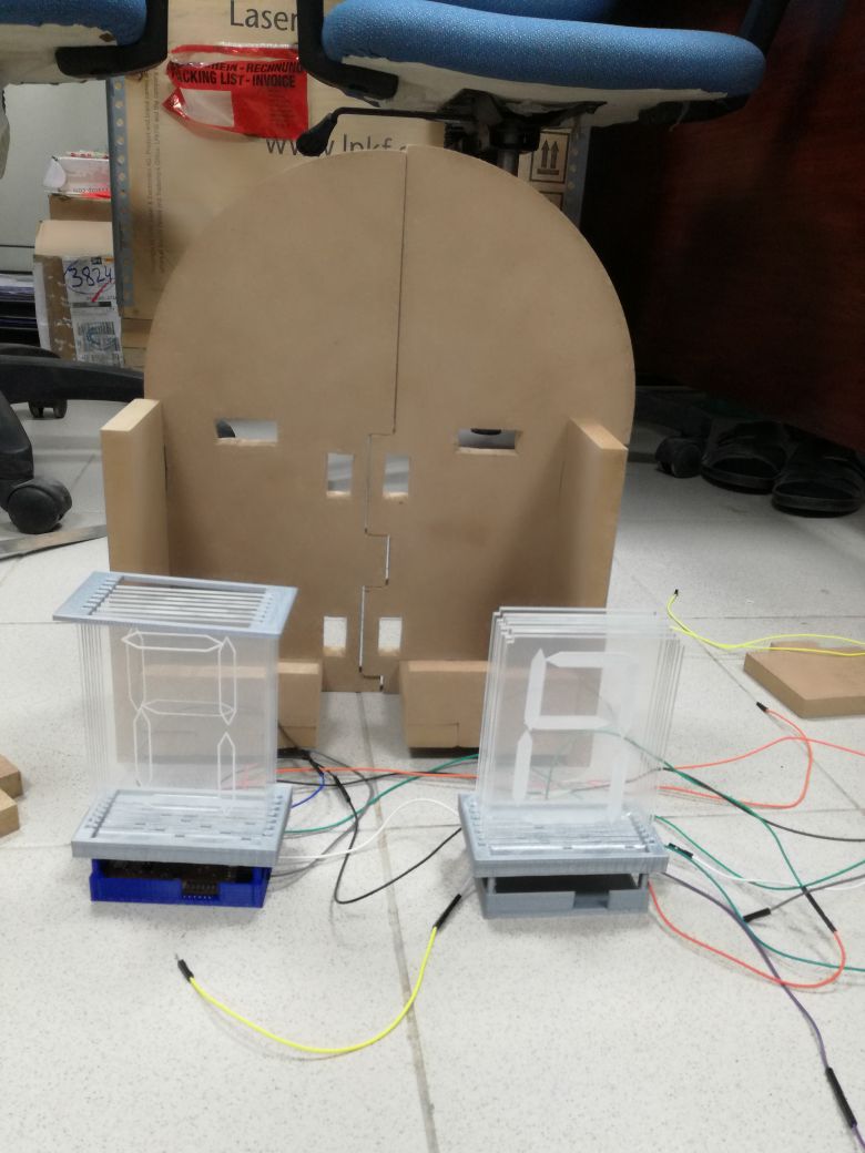
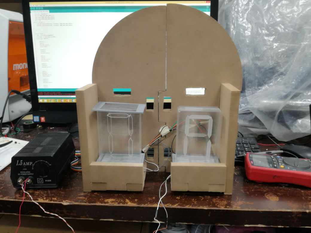
Lixie put in the Casing designed on Solidworks and cut on Shopbot
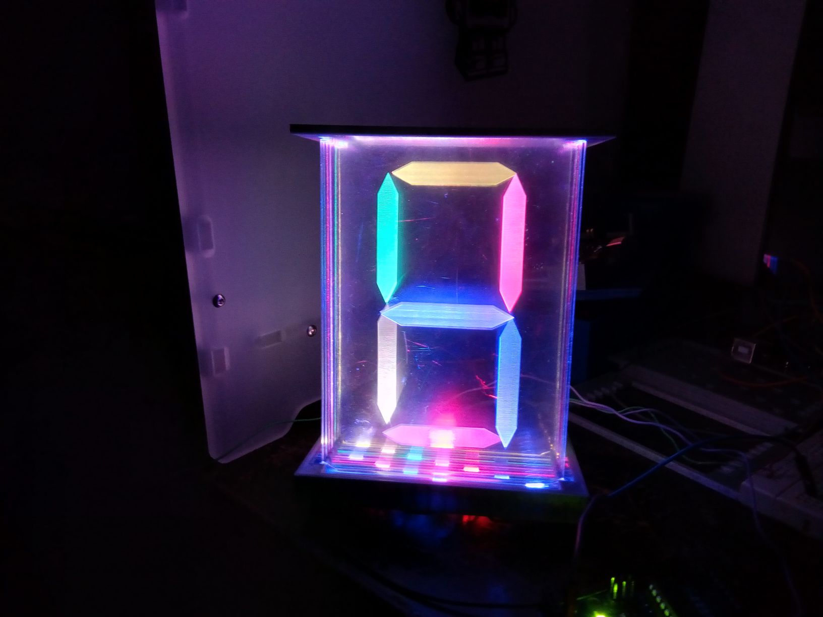
The Final Result is shown below:
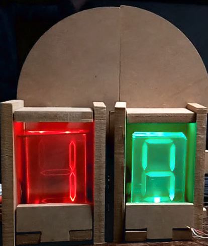
Lixie with Segmented Display with its Casing
The Final video of Demo of my final project is attached at the top of the page, along with the presentation slide.
Further Improvements
I have learned a lot while working on my Final Project . There ia always a room for imprvement, and there are many features that still need to be explored. More such Lixie Digits can be joined together to make an army of Lixies. Lixies design can be improved and some other cool features like 3D GIF can be made.
All the files for the Final Projectare attached HERE

This work is licensed under a
Creative Commons Attribution-NonCommercial 4.0 International License
.