

Success is a journey, not a destination
Group Assignment:
- test runout, alignment, speeds, feeds, and toolpaths for your machine
Individual Assignment:
- Make Something BIG!
Group Assignment
We are unable to do this week task on time because our ShopBot iss not in operational condition, so we will complete the designing part and leave this week's task until Mr. Francisco Sanchez who is in contact with our instructors comes to fix the machine. He showed up in Week-12 and he taught us to run the ShopBot, and about making Composites too.
In group assignment we have done two things, as our machine is working for the first time, we need a flat surface platform for it. Second, we made a test part which helped us to set the size of slits in our Individual Assignments.
Flattening the Platform
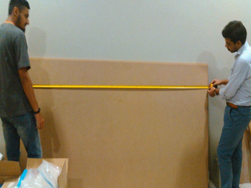
Taking Measurements
We are provided 8x4 ft 17mm MDF Wood boards for working on this week task,we use MDF board as platform for our Shopbot, but after checking the thickness we found that the board was not 17mm thick on each side.
We also measured height and width of the board because while creating toolpath we need to feed these input also
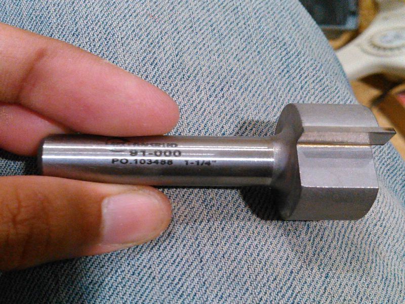
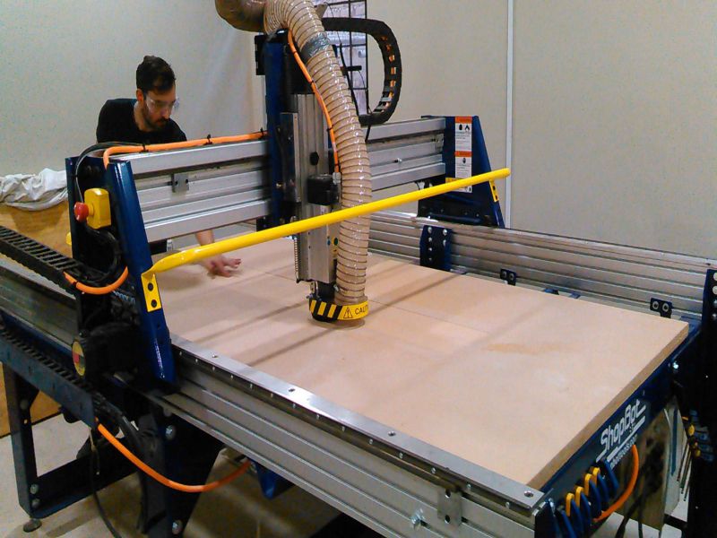
To make the surface flat we are using spoiler board cutter which shaves board to same thickness.
Generating Toolpath:
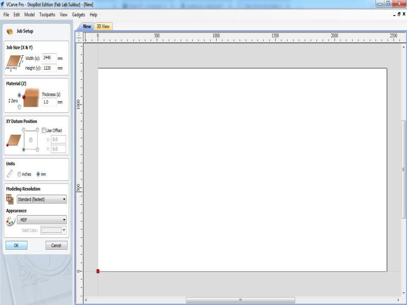
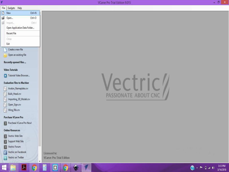
We are using VCarve Pro Software to generate the G-Code for ShopBot, below we described each step for this process:
- Double click on VCarve to open it
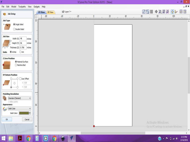
- Fill the job setup menu by entering board dimensions (width, height and thickness), set the XY Datum Position by clicking on bottom left corner, set units (our dxf files are in millimeter so we select "mm" in this column) and in last for appearence we select MDF because we are using MDF, then click "OK" for file operations.
- To generate a toolpath a vector is required, so we draw rectangle on whole board.
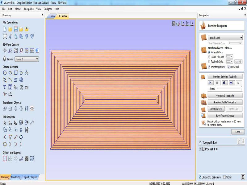
- after making vector now we are setting up the toolpath. Click on "Pocket toolpath" option in toolpath tab, then set the cut depth to "1mm" this shaves the whole board over 1mm, then select the "tool", in our case we select 1/4" Spoil-board cutter (the picture of the tool is mentioned above). Now select the vector, name the toolpath and click on "Calculate"
- After calculate the toolpath it is good practice to check the Preview of toolpath, if something is not shown right then change the settings and again generate toolpath.
- If everything is correct in preview save the toolpath by checking post processor and set it to the dimensions we use to make the file. and then click on "Save Toolpath(s) to File", this can generate .sbp file which is used by ShopBot as instruction to work on job.
- Generated .sbp file is given to shopbot, after setting x,y and z coordinates, we click on "Cut" in Shopbot panel to start the job
Making Test Part for Press-Fit
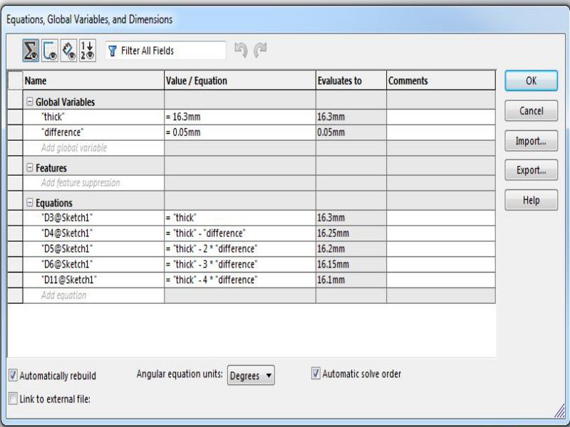
Most of our assignments are press fit so we made a test part with different thickness slots to check in which slot the wood is better press fit. The design is made in SolidWorks while using two parameters, one is average thickness of material and other is the "difference" which is used to set the slot sizes.
Using "Line" tool and "smart dimensions" we made this little piece of 60x150mm.
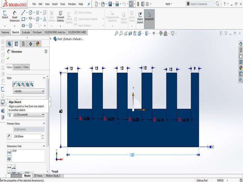
For VCarve we need a file in .dxf format and to make a dxf in Solidworks first we need to open the file in "drawing" window then save it as .dxf
After making test part design we are instructed to prepare our week assignments and set them along with test part in VCarve for job.
Making Something BIG !
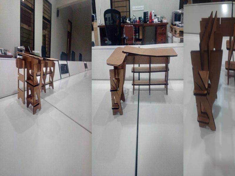
This week's assignment is to make any furniture model, with the capability of press fit construction. I searched throught internet and I found very cool designs to make one. Initially, I tried to design a simple Press-fit Desk as shown below.

The design was quite simple, but the model didn't look catchy. So, I found some other deesigns on Thingiverse.com I found the design of a corner table I decided to change a few things in the design , according to the spatial requirements of our lab. I reduced the dimensions also , so that I can use the available resources without getting into trouble.
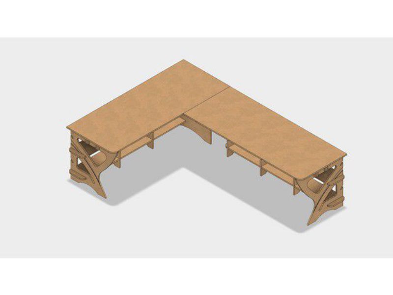
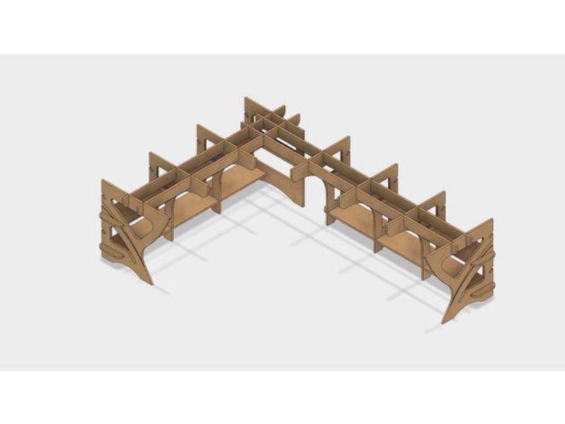
The design is simpe, but needed a lot of work done with accuracy!. I modified a few things in the design according to bed-size of shopbot, and kept the dimensions according to a normal chair in our lab.
Step-01
CAD Design of the furniture
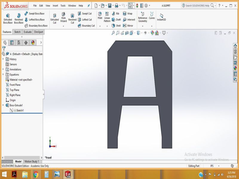
I used solidworks to make the CAD design of my model.I have been using Solidworks since weeks , so I found it comparatively easy. Being a parametric software ,it allows us to make the changes in design. Thw whole proceess of making the individual parts, and
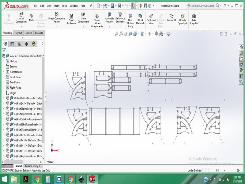
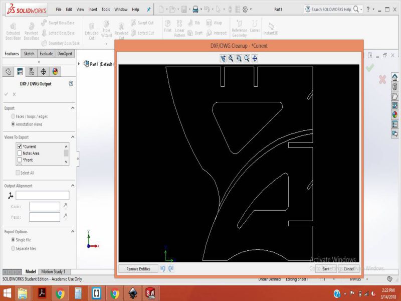
The .SLDPRT files of individual parts built in SolidWorks are provided at end of this page. The design is made according to the specific parameters required for shopbot. So, in order to reduce the scaling and make the file suitable for laser cut. I saved the files as .DXF and exported to svg.
Step-02
Exporting the .DXF files to SVG for Laser cut
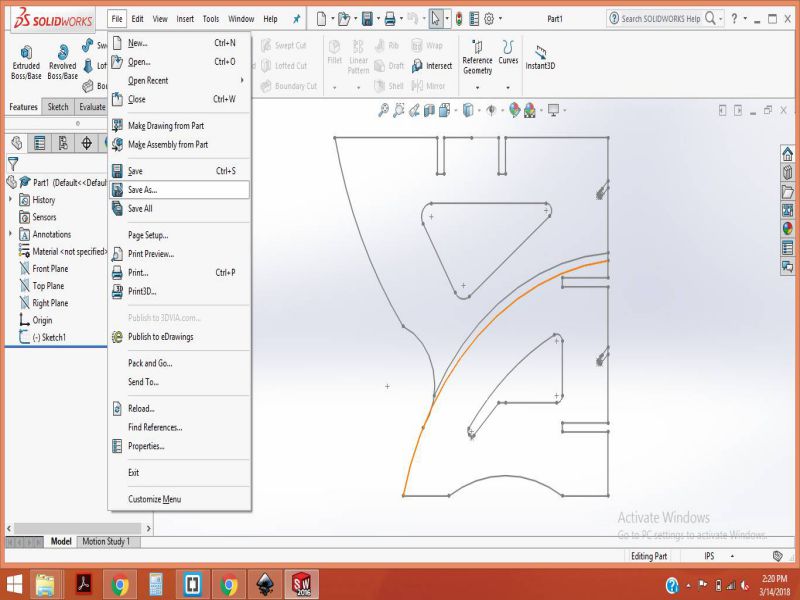
Follwoing are the steps required for exporting the .sldprt file into .dxf format and then into .svg file for laser cut.
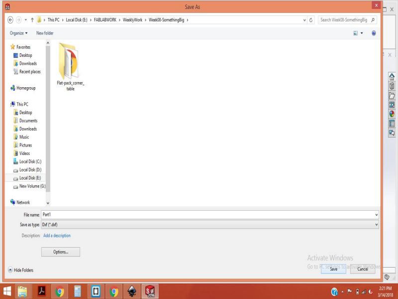
- Open the required solid part file , then click on "Save As"
- Now select the ".DXF" extension
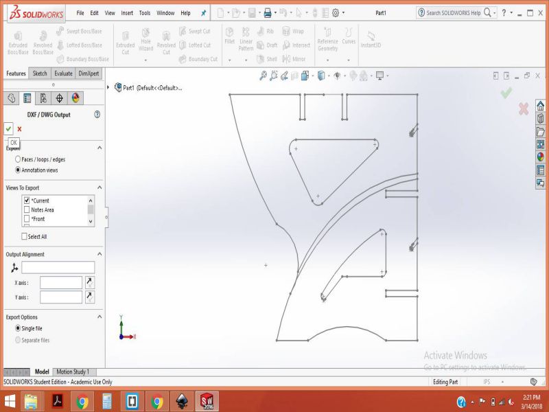
- Now click on the "green check sign" to save the changes.
- The .dxf file will open, save this file.
Now, simply import the .dxf files into the Inkscape and set the "stroke style" equal to "0.001 inches" for Laser cut. I also made some changes to the width of each slits designed for making the model as press-fit . The width of each slit is set equal to 4mm , because the material is cardboard for test purpose.
Import the .dxf file to SVG and make the required changes , set the stroke style to "0.001 inches" and set the slit dimension to "4mm".
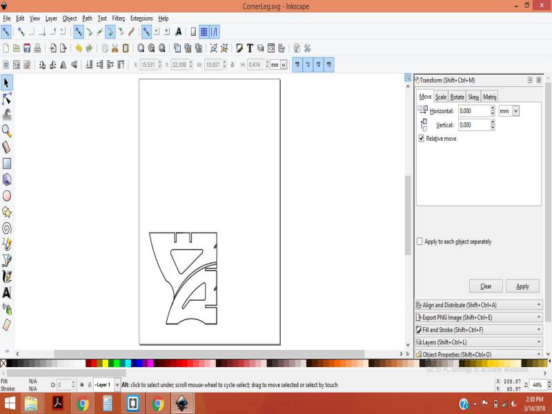
All the parts are show in the svg file below
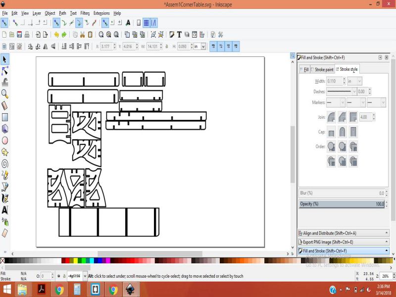
In the same manner, I made the changes in all parts and finally , the file is ready for laser cut.
Step-03
Laser cut
The .svg file is saved as pdf. The pdf file is opened in Epilog JOB Manager. Following image shows LASER at work.
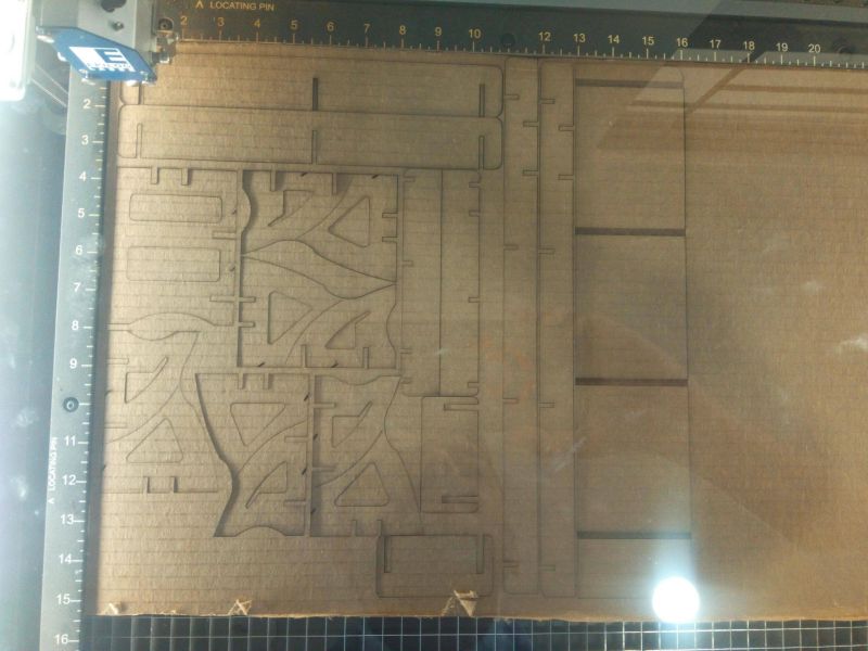
My model is Ready , and the images are shown below.
Genereating Tool Path on VCARVE Pro
The software can be downloaded from HERE , for now I'm using the Trial version of the software.
Follwoing steps are needed to generate toolpath for the shopbot machine.
- Open the Vcarve software, and create a New File
- Set the width and Height of the bed size from the Job size Tab.Click the Zero position set for Material.
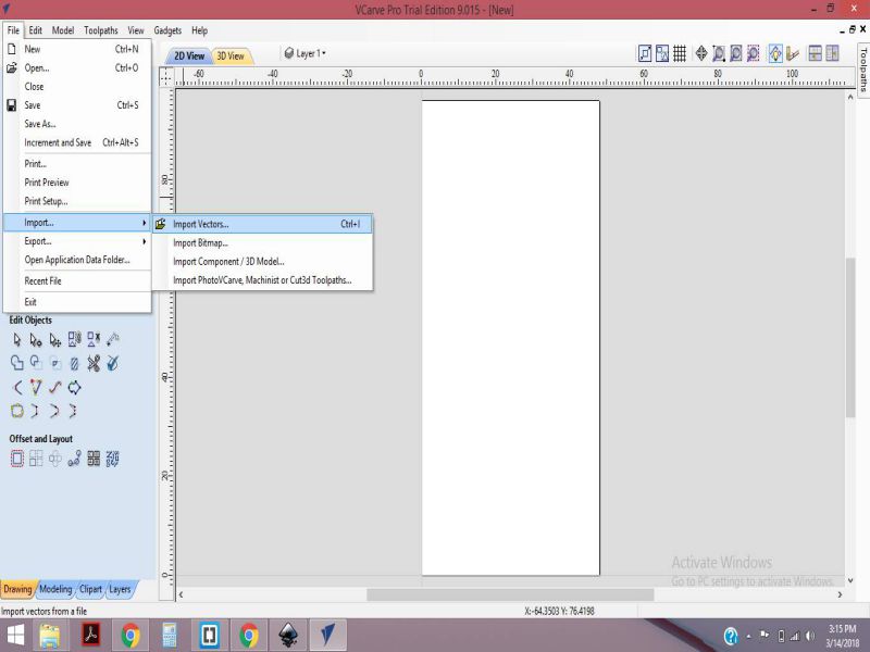
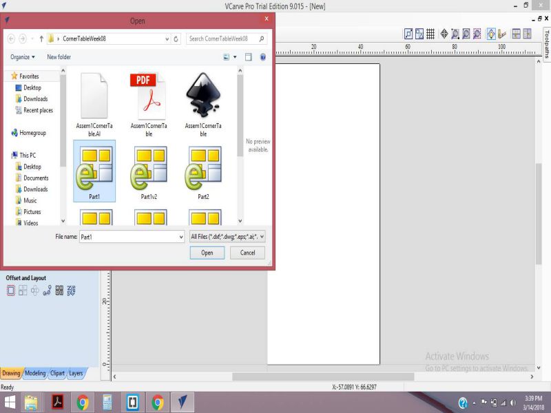
- Click on File > Import Vectors
- Click on the required File and Open it
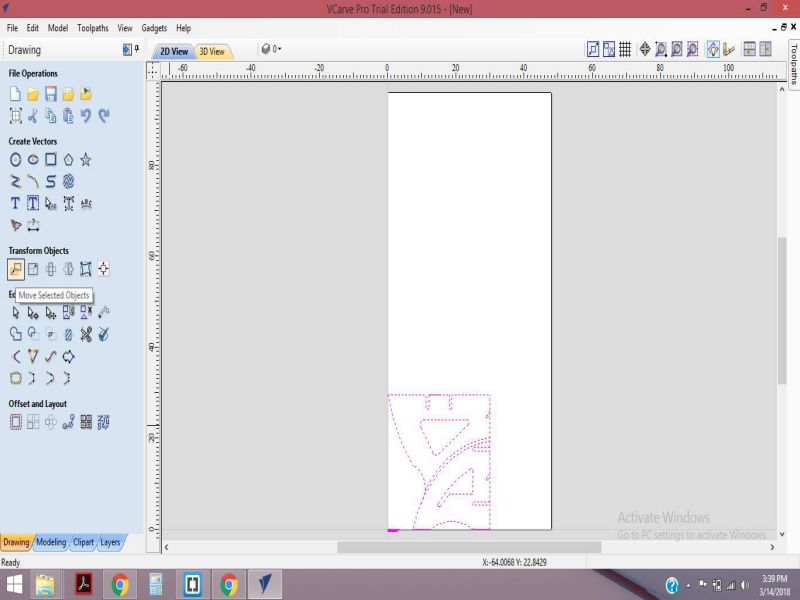
- From the Transform Objects tab, click on Move selected object
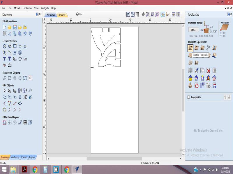
- Now, select the show toolpath Tab from toolpaths
- Select the Profile Toolpath
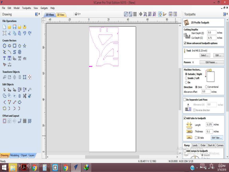
- Set the cut Depth equals to 0.71 inches. Click on Outside/Right for Machine Vectors. Set the Direction as Climb.
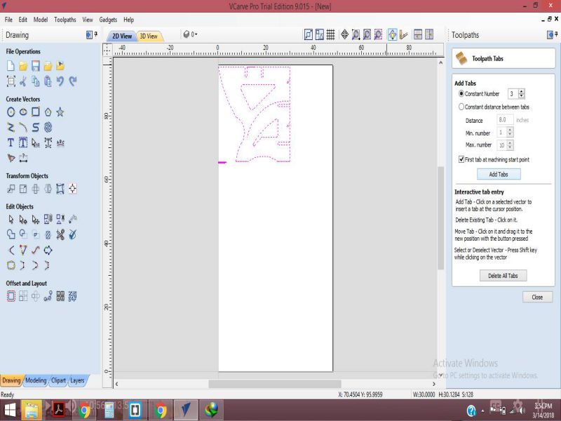
- Click on Edit Tabs, and make the settings as shown in the Figure below.
- Set the Contact Number to 3 and click on Add Tabs.
- The next step is to calculate the Toolpath and saving it as a .sbp file for shopbot Machine.
- To save it, click on Save toolpath, and then select the toolpaths generated by you.Then by clicking on Play button check the preview of working of machin.
- the following GIF file shows the toolpath generation
Unfortunately , our shopbot waasn't functional this week, so I couldn't complete my assignment this week. There were also some faults in my design , that I cut on the laser cutter also. I planned to change the design , so that I can complete my assignment without difficulty.
Make Something BIG IDEA 2 !
As I was left with short time, becuase Mr. Francisco Sanchez Arroyo arrived during our Week 12. He has to make our shopbot functional and teach us the all the required steps. He also taught us about the safety measures. In addition to it, he also made us learn to make a composite. It was a great time with such a nice person , and an skilled Engineer , It was my pleasure to be part of the team.
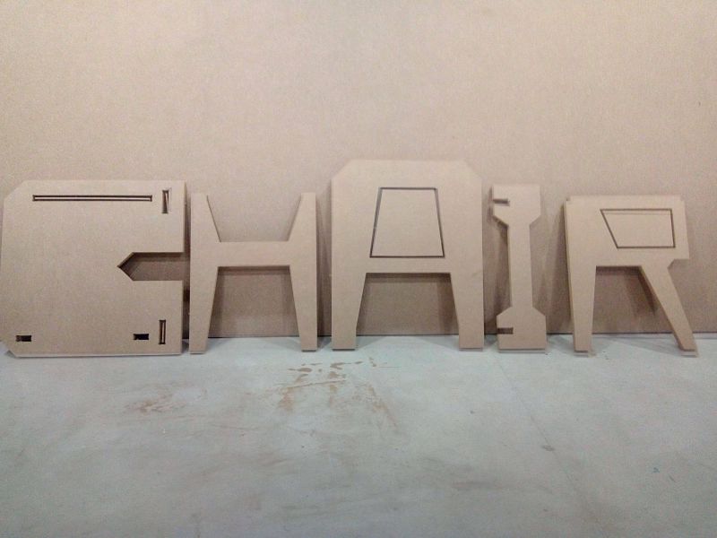
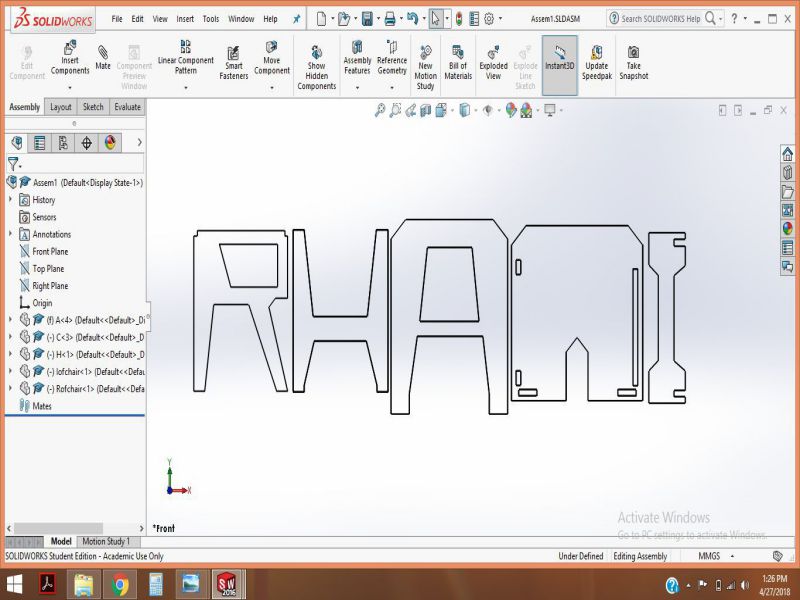
Coming to my Assignmet! I decided to make a CHAIR . The cool thing about this design is that it looks cool, and requires less time to make tha CAD model. It also needed less resources, and I made the dimensions according to a normal chair that we use in our lab.Below is the chair that I made and the model I found on internet.
.jpg)
.jpg)
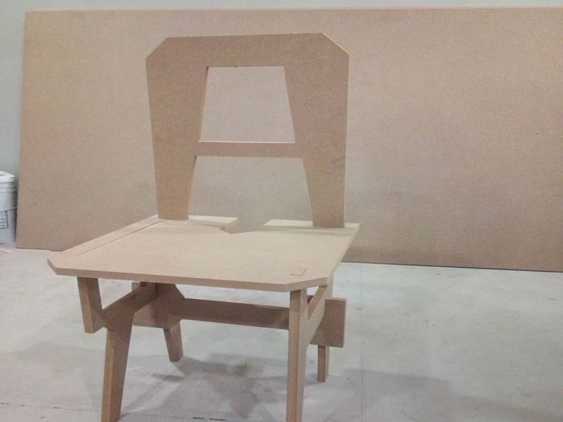
In order to make this chair, I had followed the steps given below:
Step1: Making the CAD model
To make the CAD model , I used SolidWorks. I have worked on SolidWorks since past few weeks, so I found it easy ad effective design software to make a parametric design.I made the Individual letters as shown in the pictures below!
Open SolidWorks> Select Part > Set the dimesnions to Inch Pound System > Click on the plane on which you want to make the Sketch.
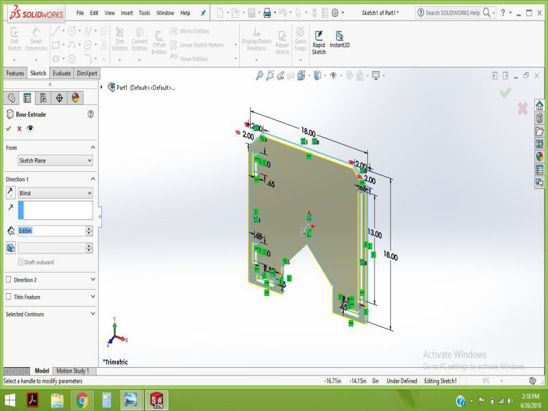
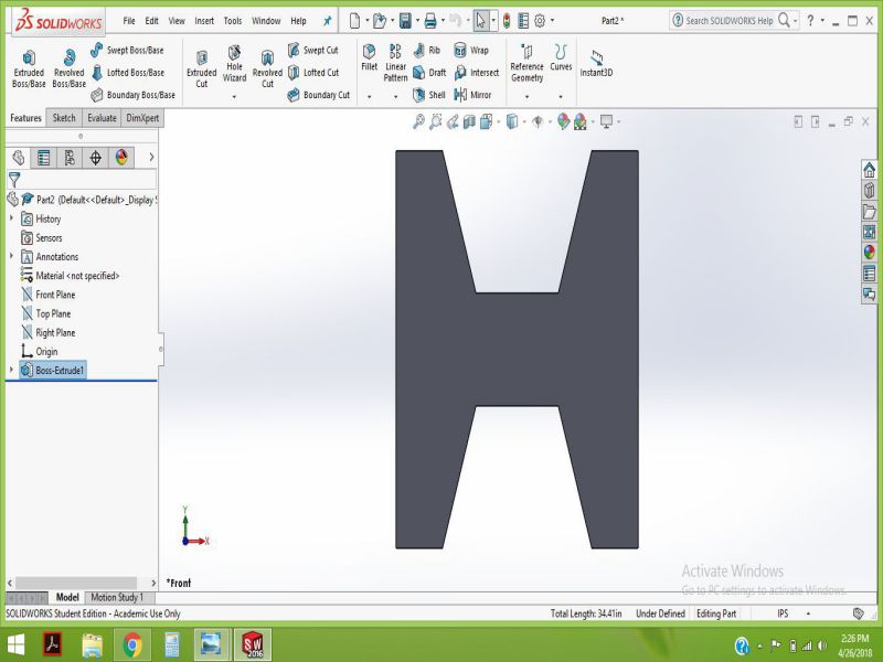
In the Same Way , I made all parts and extruded each part using Bose Extrude just to check it in Assembly.
Step2: Exporting the solid parts Files as .DXF
All the steps for generating a DXF file from .sldprt are already mentioned above in the previous design attempt.
I opened the .DXF files in Inkspace and saved the .SVG file as .PDF
Step3: Genreating the .sbp File for Shopbot
- Step 01: Setting the border, and Origin on the bed of shopbot
- Open the Vcarve Shopbot Pro Software
- Open a new File
- Set the dimensions, as shown in the GIF
- Create the border, and guide Layers, and set the Origin as shown in the GIf
- Step 02:Dogbone Generation, and Arranging the individual parts to save the space
- Click on Import Vectors and select your File
- Click on the option of Join Open curves and click on join to close any open curve
- Select all the boundaries or edges and right clik, then select move layer to Outside
- Now , select the inside edges and right clik, then select move layer to Inside
- Click on Gadgets> Dogbone filter > Dogbone detect , and then Create Dogbone, do select the Dogbone fillets.
- Rotate and move each part to the desired position , for amking the proper arrangement.
- Step 03: Generating toolpath and Saving the .sbp file
- Click on the Toolpaths tab, and click on show Toolpath tabs.
- Click on the Profile Toolpath cut
- Set the cutting depth to 17mm
- Select the tool from Toolset, here we select 1/4'' downcut (57-910)
- From the Machine Vectors option, select "ON" , as we wish that the tool should cut directly on the set toolpath.
- Now, click on Edit Tabs, and Add tabs.
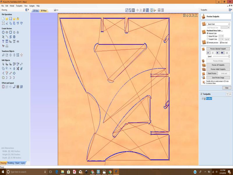
- Now, click on "Calculate" and check the "Preview" of the generated toolpath
- SAve the Generated Toolpath
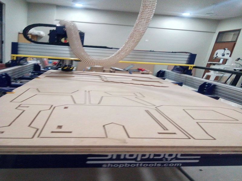
I am using VCarve Shopbot Pro Edition 8.0 for generating .sbp File for shopbot. As explained earlier in the group assignment, I am using approximately 17mm MDF wood. All the necessary steps for setting the bed-size, border, origin, dogbone-filter generation , and toolpath are shown in the below GIF files.
Now, Its time to do some work on Shopbot, and before doing that, I checked some good tutorials present on Official Website the video below discusses the important things to get started with Shopbot.
My Job took around 20 minutes, and It's ready to be displayed to everybody.
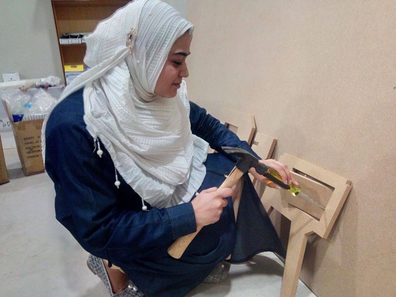
In the Final Step, I removed the Tabs and Joined the individual parts, and the job was done very well.
Conclusion
This week's task was challenging, but full of learning. Everything was very new to me , but with thesupport of instructors and Mr.Francisco Arroyo I learned to operate shopbot. I still need to do a bit more practice on it, that I will be doing for sure in my free time. The most important thing while working on shopbot are the safety measures and using the Emergency stop button to avoid any unwanted situation.
All the Files of Week8 are attached below!
Week 8 Files!

This work is licensed under a Creative Commons Attribution-NonCommercial 4.0 International License.