
An output device refers to user-computer communication devices and devices used for communication between computers, devices and other peripherals, which may be used for input/output (I/O) purposes, like network interface cards (NIC), modems, IR ports, RFID systems and wireless networking devices, as well as mechanical output devices, like solenoids, motors and other electromechanical devices.
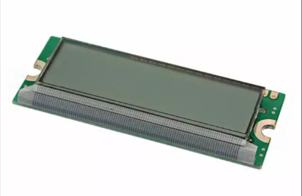
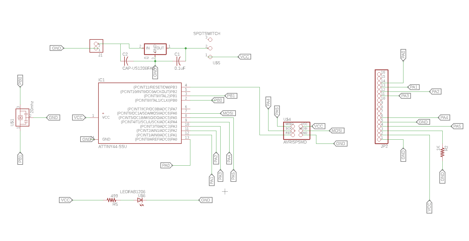
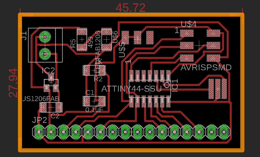
This week I decided to use LCD system as the output device. The board could be prpogrammed to display different texts according to the program. I designed the board using Eagle. I milled and cut out the board using Roland Modella. All components were soldered. I used ATtiny44 for the board. I used tinyISP to program the board.
An LCD (Liquid Crystal Display) is a standard display device for hand-held embedded systems. Today, color TFT (Thin-Film Transistor) LCDs are common even in cost-effective equipments. An LCD display system is composed of an LCD panel, a frame buffer memory, an LCD and frame buffer controller, and a backlight inverter and lamp. All of them are heavy power consumers, and their portion becomes much more dominant when running interactive applications. This is because interactive applications are often triggered by human inputs and thus result in a lot of slack time in the CPU and memory system, which can be effectively used for dynamic power management. In this paper, we introduce low-power LCD display schemes as a system-level approach. We accurately characterize the energy consumption at the component level and minimize energy consumption of each component without appreciable display quality degradation. We develop several techniques such as variable-duty-ratio refresh, dynamic-color-depth control and backlight luminance dimming with brightness compensation or contrast enhancement.
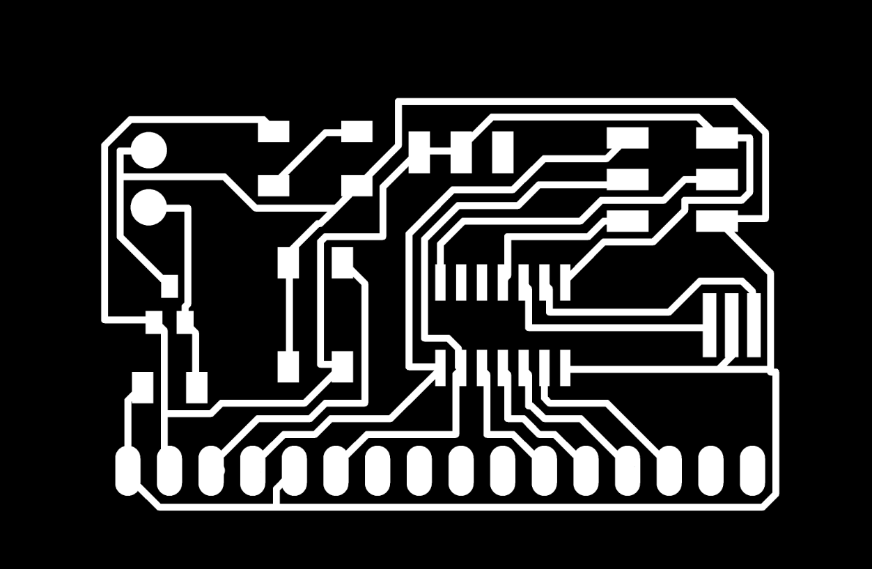
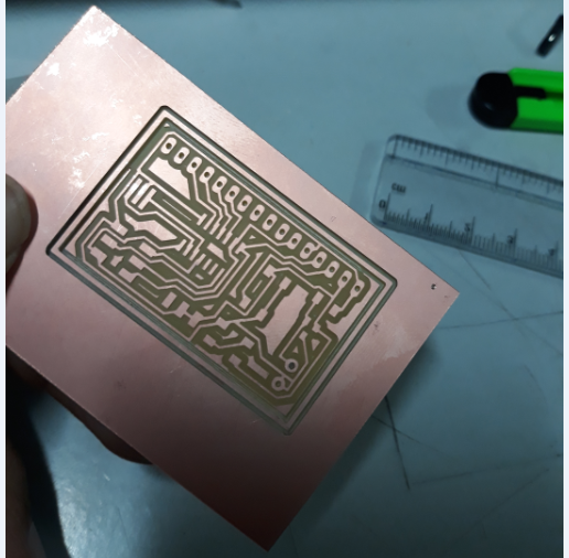
I used Neil's LCD system Circuit design available in the FAB archive as reference to design my board. I made slight modifications in the design.
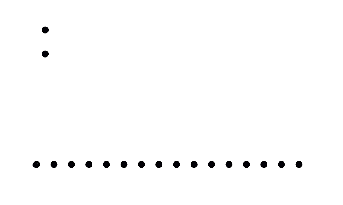
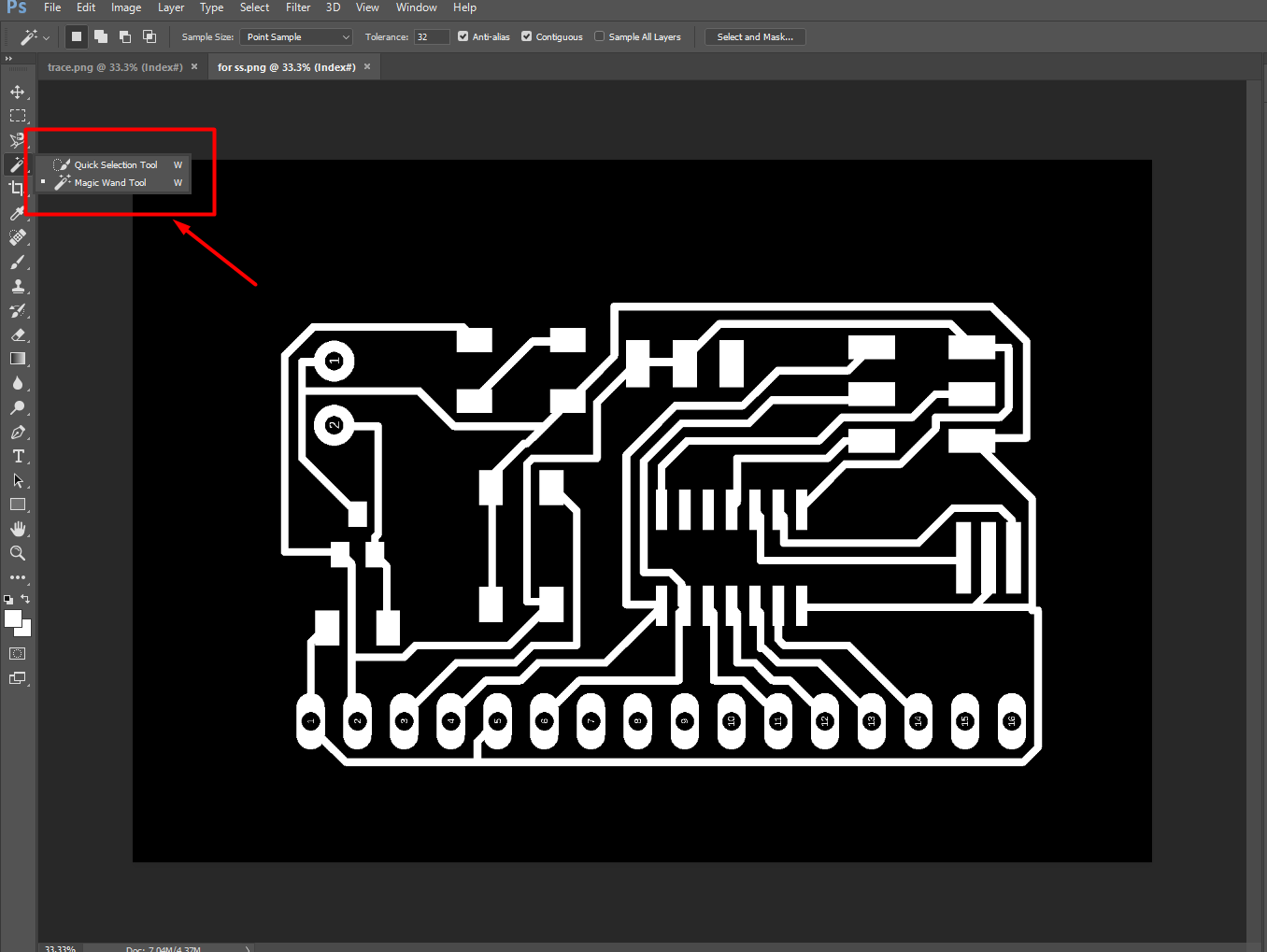
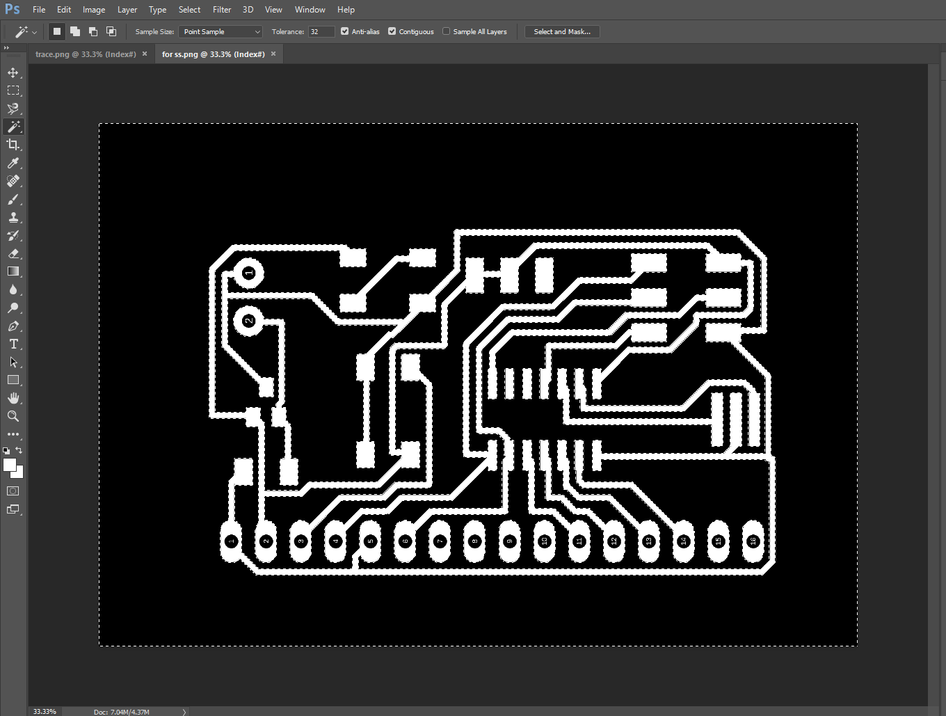
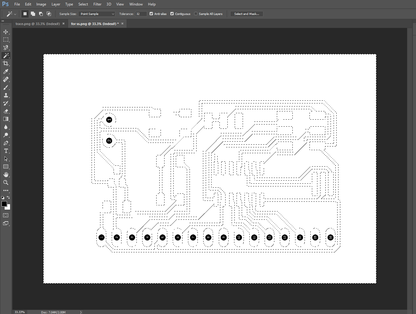
In this board the pads for the 16 pin header and the pads for the 2 pin header is shown in green. These pads are to be drilled. So a separate PNG image needs to be made to drill the pads.
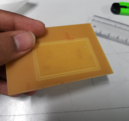
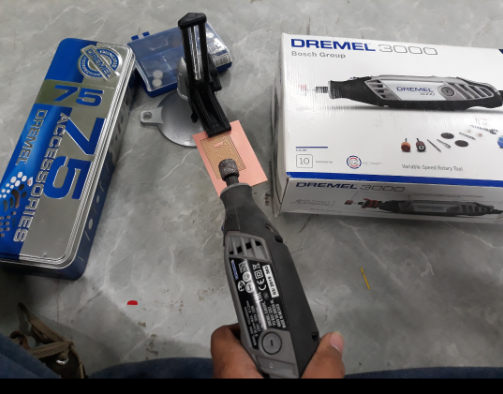
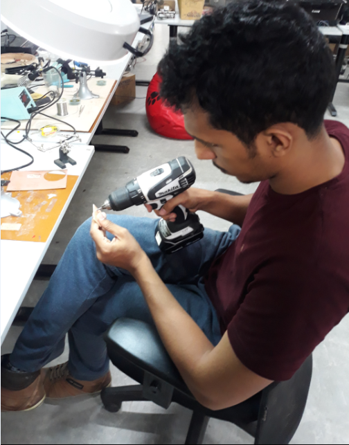
While setting the modella, I set the drill by keeping the chuck at the lowest position. This caused the machine to perform an incomplete cut. The machine only made a groove and the drill was also not complete. I then had to manually cut out the board and manually drill the holes. I lost a lot of time here.
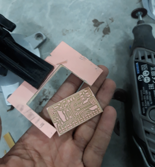

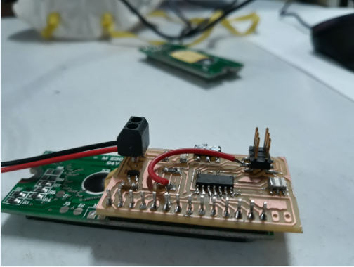
All the components were soldered. However during the soldering one of the path was cut off . I then had to use a jumper wire to complete the circuit
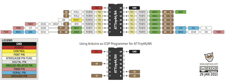
The bootloading was successful. The pins were set using the data sheet for the LCD available in the internet. You can find the data here Data sheet. The pins the LCD was compared with the data sheet of ATtiny44.
    #include <LiquidCrystal.h>

    const int rs=5, en=4, d4=3, d5=2, d6=1, d7=0;
    LiquidCrystal lcd(rs, en, d4, d5, d6, d7);

    void setup()  {
      //set up the LCD's number of columns and rows:
      lcd.begin(16,2);
      //Print the message to the LCD.
      lcd.print("YES!! I did it");
    }

    void loop() {
      //set the cursor to column 0, line 1
      //(note: line 1 is the second row, since the counting begins with 0):
      lcd.setCursor (0,1);
      //print the number of seconds since reset:
      lcd.print(millis() / 1000);
    }
Here is the video.
    #include <LiquidCrystal.h>

    const int rs = 5, en = 4, d4 = 3, d5 = 2, d6 = 1, d7 = 0;
    LiquidCrystal lcd(rs, en, d4, d5, d6, d7);

    // make some custom characters:
    byte heart[8] = {
      0b00000,
      0b01010,
      0b11111,
      0b11111,
      0b11111,
      0b01110,
      0b00100,
      0b00000
    };

    byte smiley[8] = {
      0b00000,
      0b00000,
      0b01010,
      0b00000,
      0b00000,
      0b10001,
      0b01110,
      0b00000
    };

    byte frownie[8] = {
      0b00000,
      0b00000,
      0b01010,
      0b00000,
      0b00000,
      0b00000,
      0b01110,
      0b10001
    };

    byte armsDown[8] = {
      0b00100,
      0b01010,
      0b00100,
      0b00100,
      0b01110,
      0b10101,
      0b00100,
      0b01010
    };

    byte armsUp[8] = {
      0b00100,
      0b01010,
      0b00100,
      0b10101,
      0b01110,
      0b00100,
      0b00100,
      0b01010
    };

    void setup() {
      // initialize LCD and set up the number of columns and rows:
      lcd.begin(16, 2);

      // create a new character
      lcd.createChar(0, heart);
      // create a new character
      lcd.createChar(1, smiley);
      // create a new character
      lcd.createChar(2, frownie);
      // create a new character
      lcd.createChar(3, armsDown);
      // create a new character
      lcd.createChar(4, armsUp);

      // set the cursor to the top left
      lcd.setCursor(0, 0);

      // Print a message to the lcd.
      lcd.print("I ");
      lcd.write(byte(0)); // when calling lcd.write() '0' must be cast as a byte
      lcd.print(" Arduino! ");
      lcd.write((byte)1);

    }

    void loop() {
      // read the potentiometer on A0:
      int sensorReading = analogRead(A0);
      // map the result to 200 - 1000:
      int delayTime = map(sensorReading, 0, 1023, 200, 1000);
      // set the cursor to the bottom row, 5th position:
      lcd.setCursor(4, 1);
      // draw the little man, arms down:
      lcd.write(3);
      delay(delayTime);
      lcd.setCursor(4, 1);
      // draw him arms up:
      lcd.write(4);
      delay(delayTime);
    }
This code is based on an animation which can be done using the LCD. The video is below.
Click here to download the design file.