The fourth week is where the design tools are going to become handy. Prof Neil explained about various
cutting tools available , various types of Laser etc.
The precautions needed to be taken before operating the Laser machines were also explained. It is
mandatory that the operator stays with the machine throughout the operation.
This is because since the machine cuts by focusing a large amount of energy at a particular point, there
are chances that the work may catch fire.
The machine cuts various material however metals cannot be cut using Laser. The reflecting surface
will reflect the light back into the laser causing severe damage to the machine.
Also random plastics cannot be used as work material. All laser cutting machines are equipped with an
exhaust system that draws out the poisonous gases emitted during the cutting operation.
The operator should wait for a minute or two before opening the lid of the machine to remove the work
after the cutting is done.
Assignment
Vinyl cutter
Cut something using the vinyl cutter
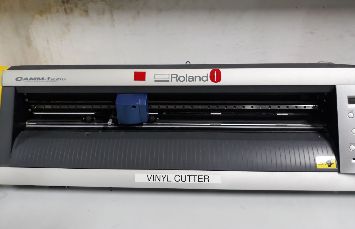
Roland MDX camm-f SERVO
A vinyl cutter is a machine that cut the vinyl according to the design
fed into the computer. A computer Controlled blade cut out the shape precisely
using fab module.
Setting the machine
Release the pressure by operating the pressure handle on the left side of
the machine. Insert the sheet from behind.
There are rollers in the machine that keeps the sheet in place. These rollers are to be
positioned exactly under the white lines seen on the machine. Otherwise the
machine will display the message "BAD POSITION".
When the machine is turned on the tool head moves to the home position.
Now select the type of piece. Whether sheet or piece.
Now the machine will automatically roll the sheet forward and measure the length
and breadth of the sheet fed.
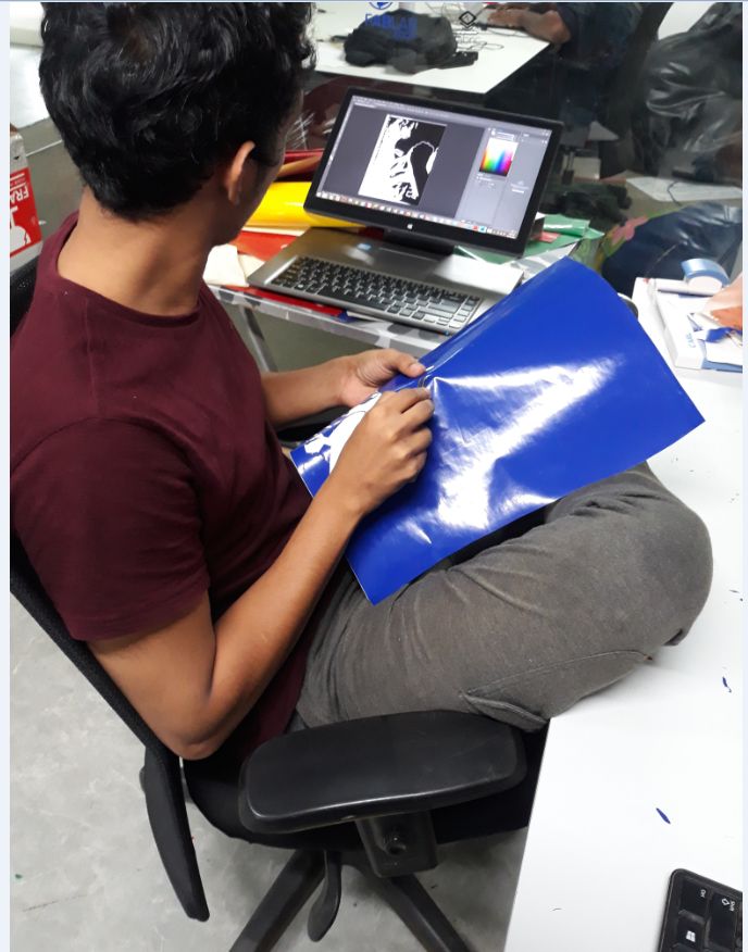
Cutting
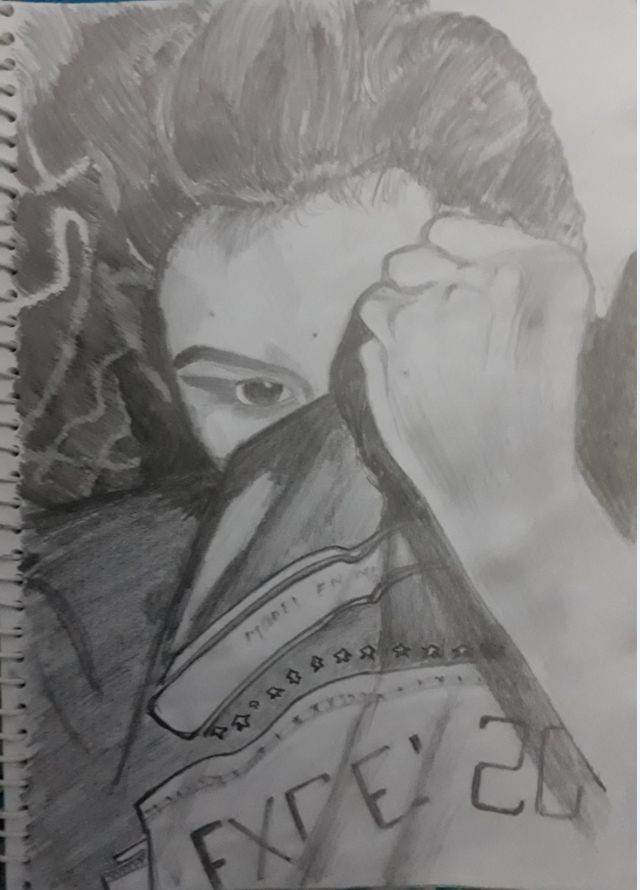
For cutting the vinyl i was thinking of converting a picture i drew by hand into a
digital file.
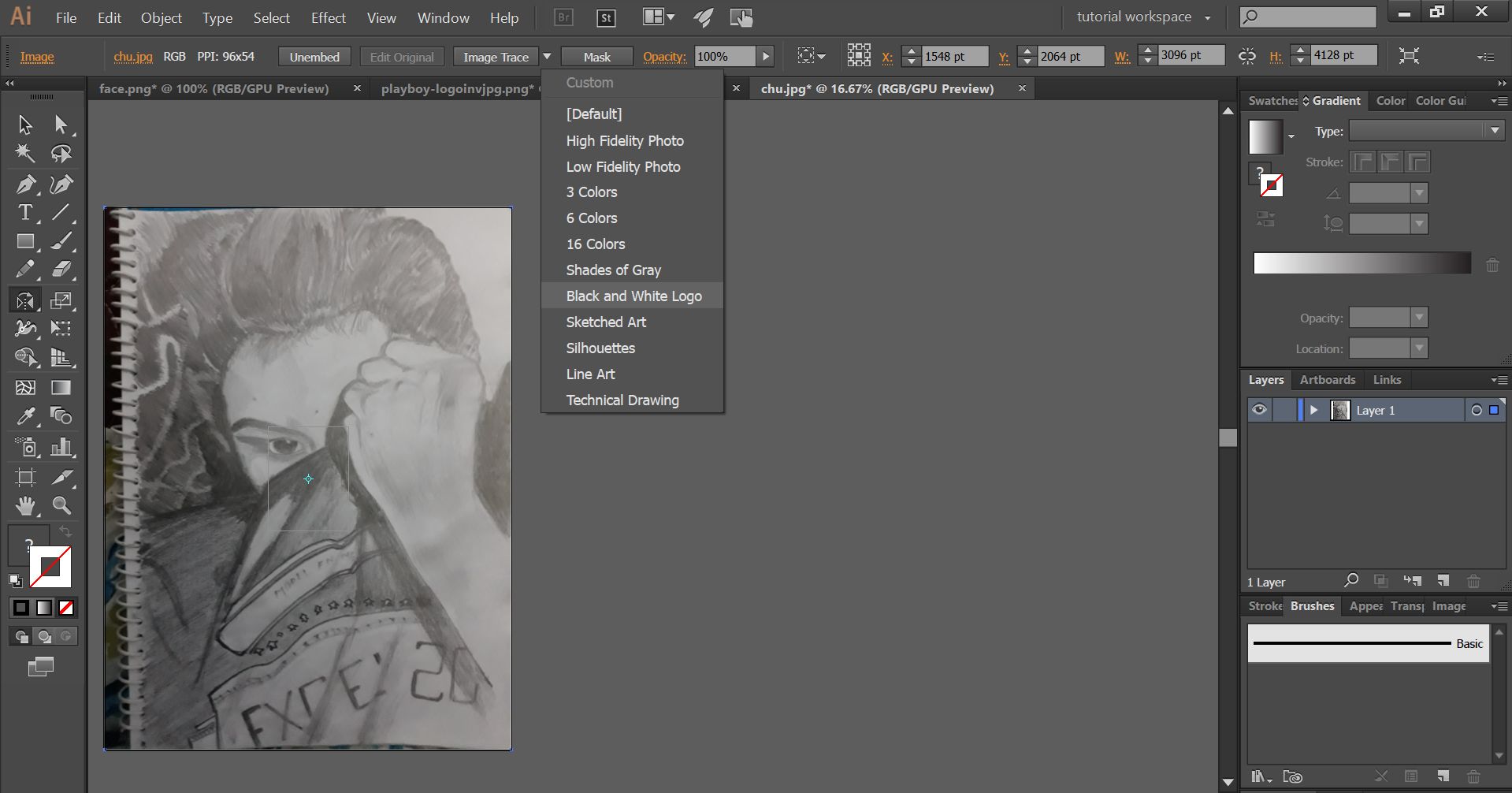
For this I took a picture of the drawing and imported the file into Adobe Illustrator
Once the image is loaded it is converted to monochrome image by taking
the trace of the image.
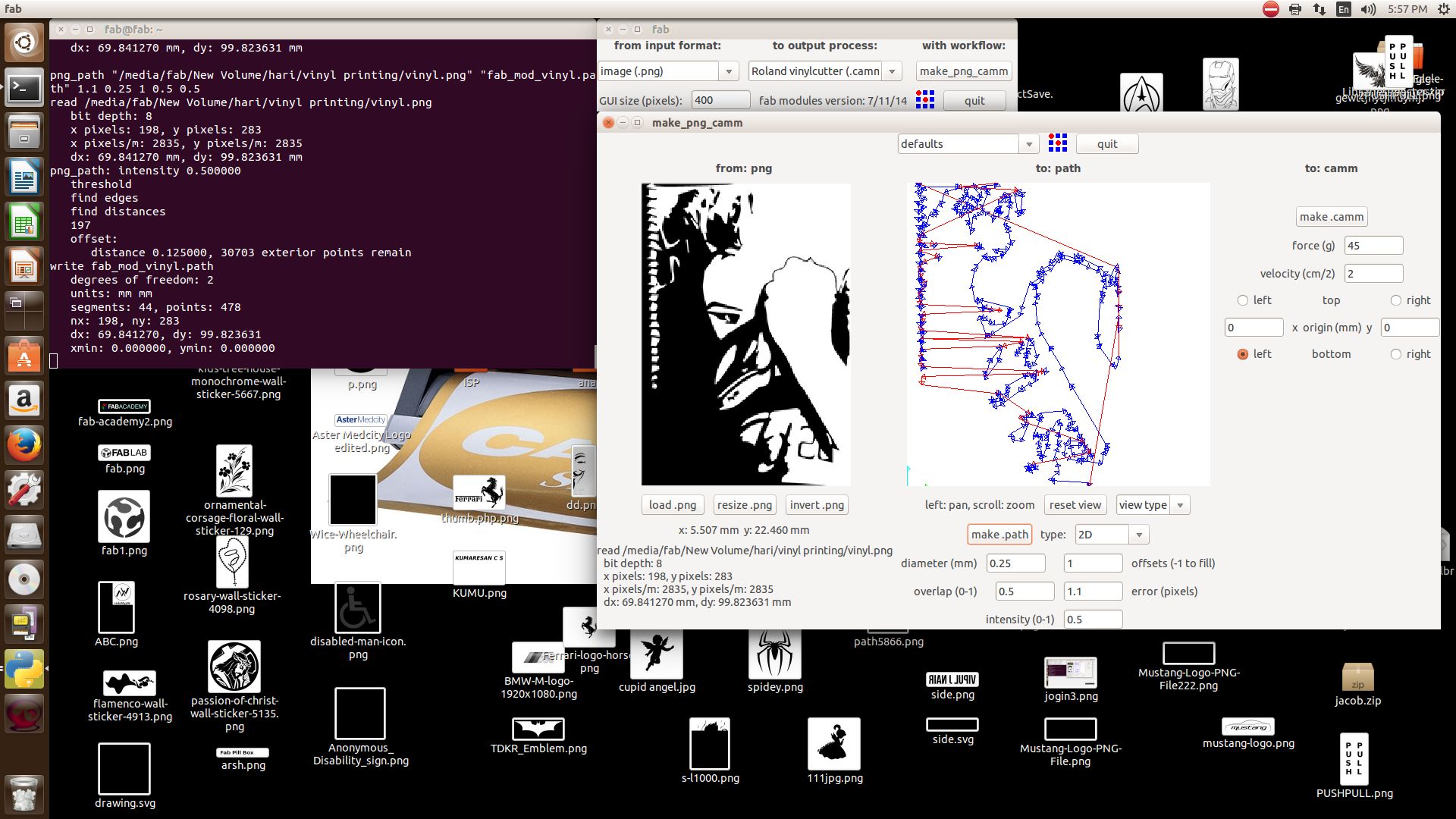
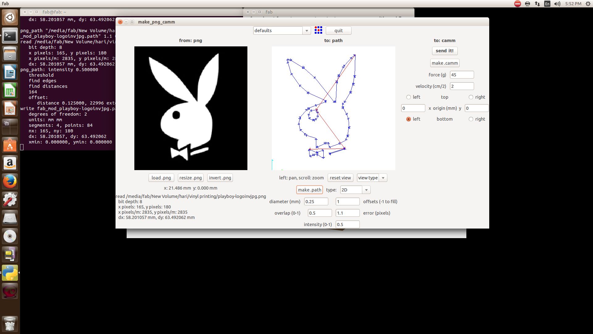
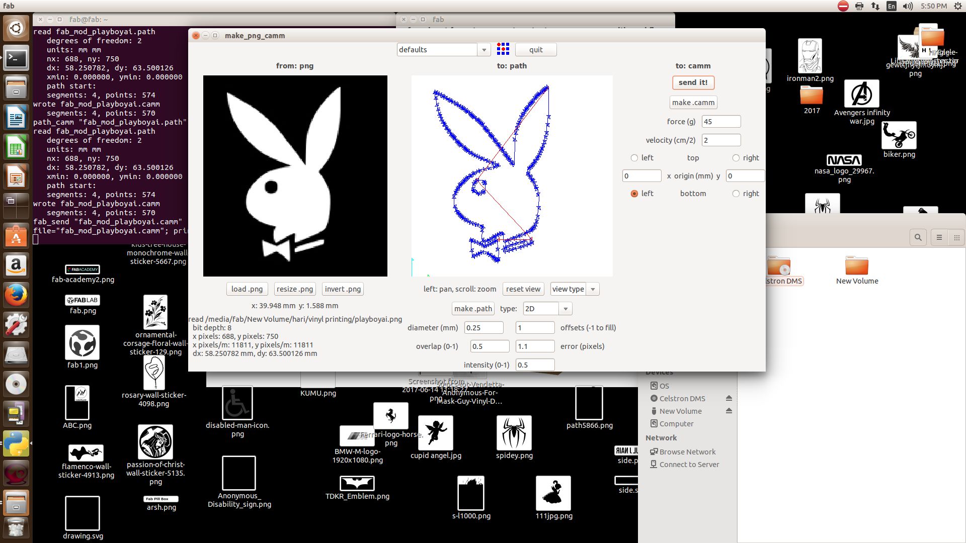
Load the png file into fab module. Make path and make .camm. Then click on
send it.
The machine now cuts the image on to the sheet. Once the sheet is cut remove
all the small parts of the image that you dont want using forceps.
Remove the cut out from the sheet using a masking tape and stick in on the desired surface.
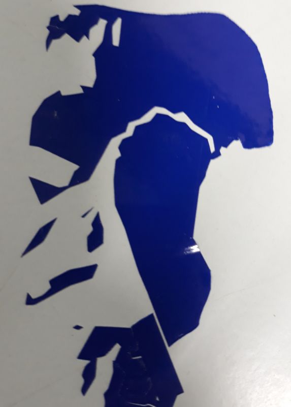
The final look
Since the image was complex the ouput was not good enough to understand the image.
Trying to understand the difference between images loaded in Raster and vector
To understand the difference between the images loaded into fab module I generated
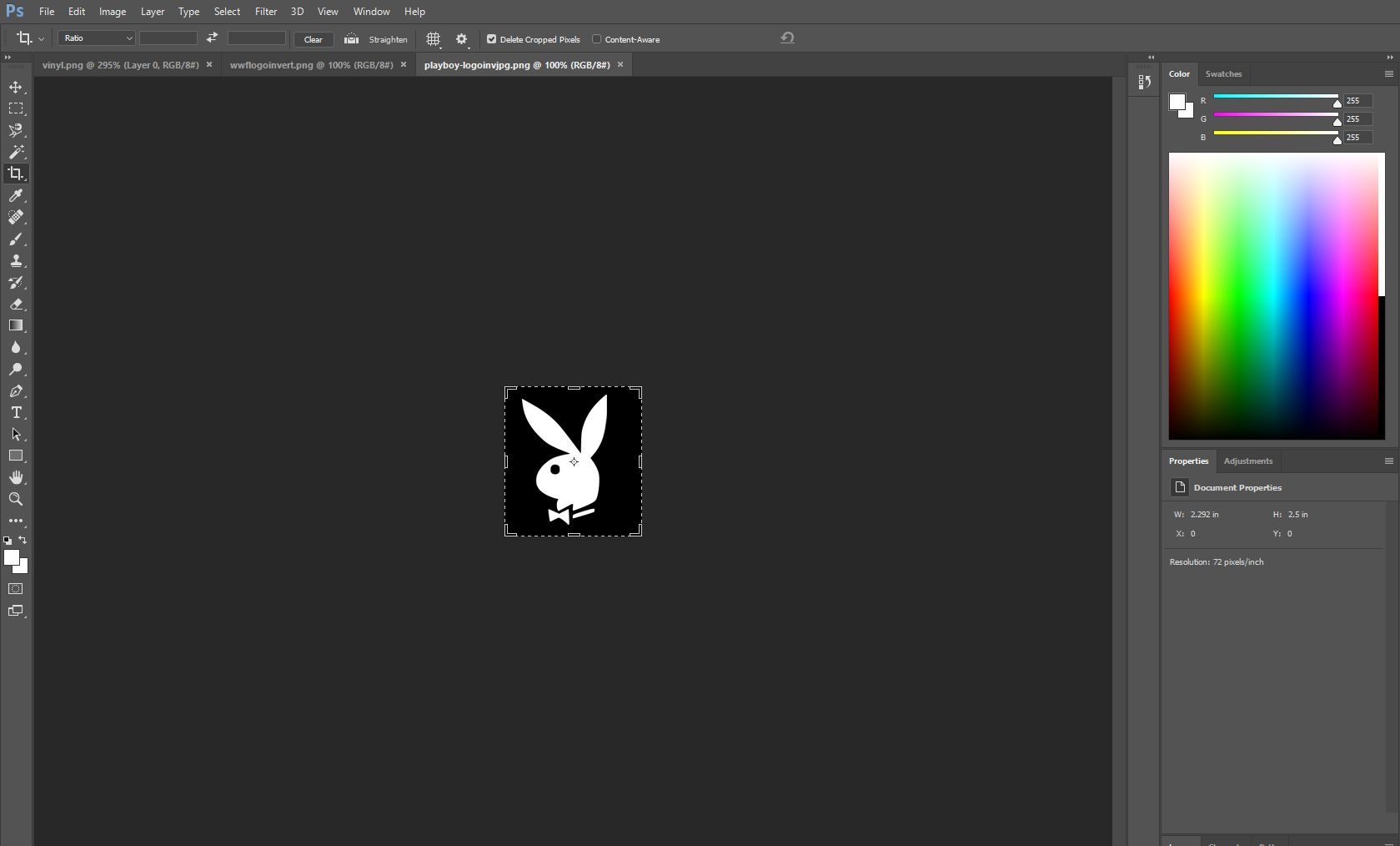
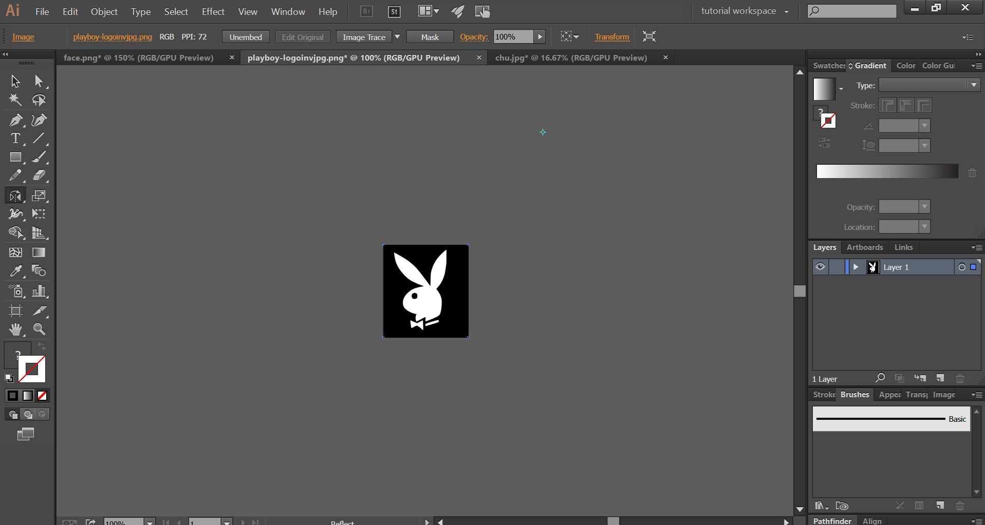
two PNG images. One using Adobe Photoshop and other using Abode Illustrator
Adobe Illustrator and Photoshop
Adobe Photoshop
Adobe Illustrator
The difference is understood when the images are loaded into the FAb module.
When the path is generate the image from photoshop has more straight lines whereas
the image from Illustrator has more cuts and maintains the shape of the image to
the best possible accuracy
Adobe Photoshop
Adobe Illustrator
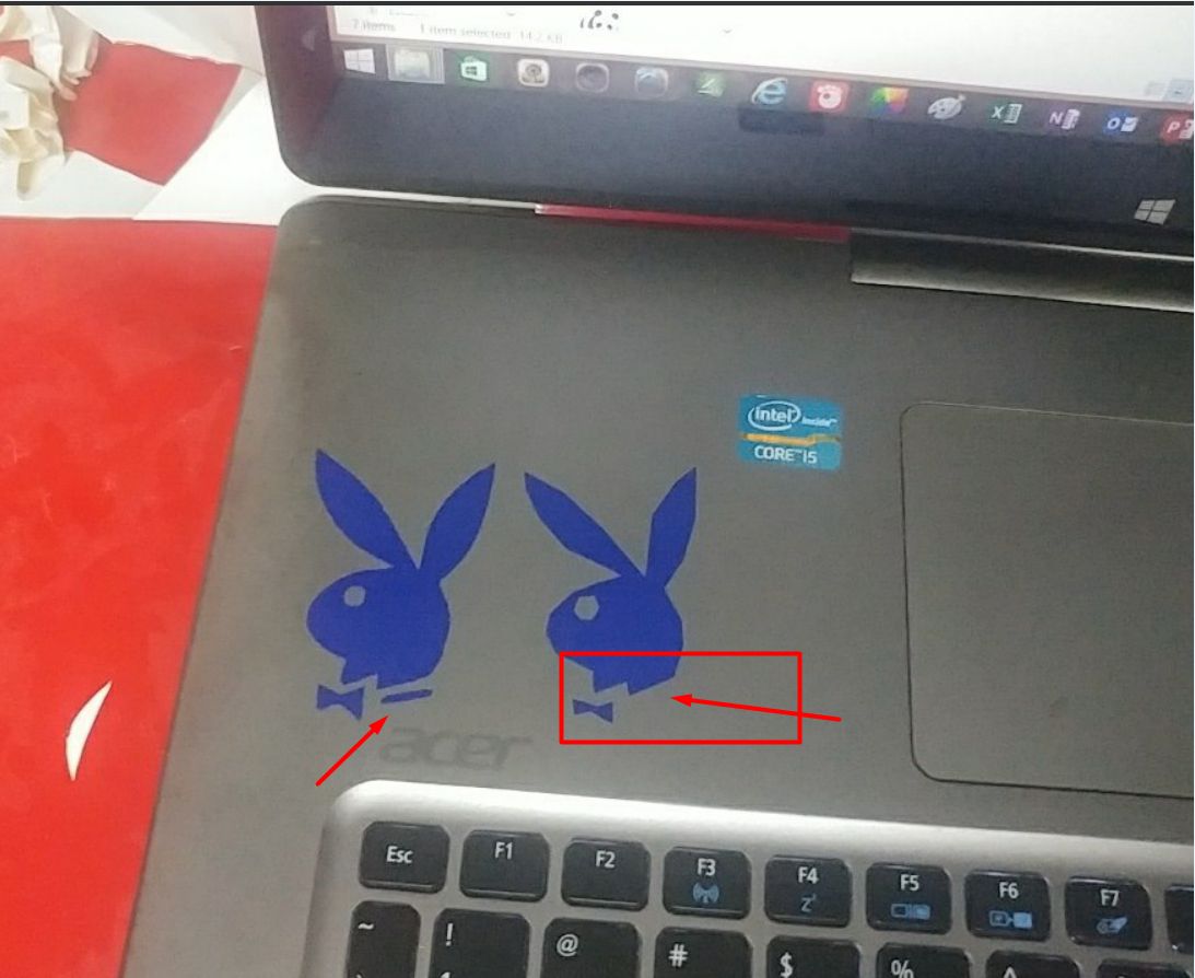
The final output
Notice that the image from photoshop(right) is missinig the collar line. Also the overall
appearance of the two images are different. One has smooth curves and the other
has more straight lines.
This is because of the resolution problem of the image generated using a Raster.
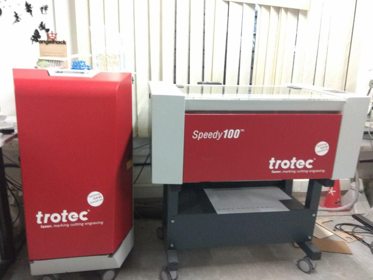
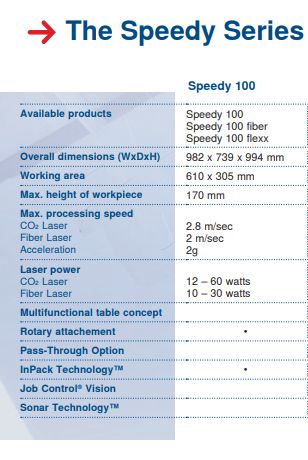
The machine we use in the lab is the TROTEC SPEEDY 100. A laser cutter works by focusing a high energy beam
of light in a really small area to vaporize the material there.
TROTEC SPEEDy 100 uses a Carbon Dioxide(CO2) laser. The laser beam is generated behind the machine and it is diverted by
an arrangement of prims to focus the beam on the job.
The beam moves through the set contours using CNC arrangements. The motion is only possible in 2D.
Machine Details
The Speedy laser engraving and cutting systems are the perfect choice both for
entry level users as well as professional engravers. „Speedy“ – the fastest and most
productive laser machines in the market: By processing at maximum speed of 3.55 m/sec and
acceleration of 5g the Speedy is designed to increase your production efficiency.
Thanks to the closed construction, essential components are protected from dirt and dust.
This is why you can operate without virtually any maintenance and cleaning requirements.
This results in higher up-time and lowest cost of ownership. All platform sizes from 610 x
305 mm up to 1000 x 610 mm are available with a CO₂, a fiber or even both laser sources in one
laser system. The patented flexx function enables
endless application possibilities. Use both laser sources in one job without having to change the laser source, the lenses or the focus manually
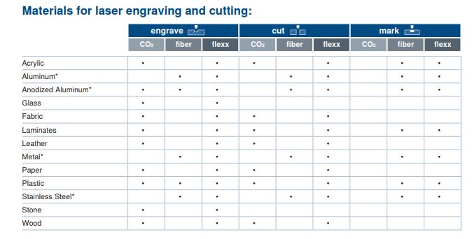
Materials for Laser cutting and Engraving
In the lab we mainly have cardboard, acrylic and ply wood sheets for working with the machine.
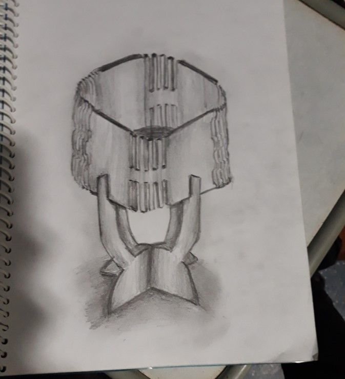
Laser cutting has always fascinated me. The Assignment was to make a structure with press fit
This required a lot a designing. I was planning to create a lamp shade like structure as below
The material used for construction is Cardboard. I used Solid works to design the whole structure.
The basic design incorporated is quite simple.
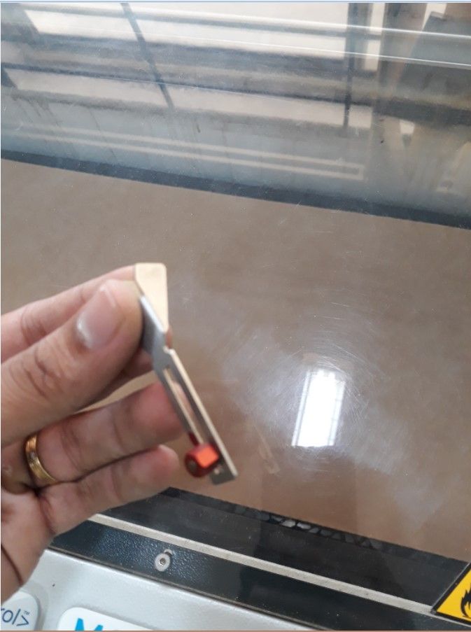
Focusing
Before the cut is made the laser has to be focused For this there is a focusing tool available with the
machine. This is placed on a small groove in the Laser and the bed is raised until it touches the tool.
The tools drops from the groove when the bed touches it indicating that the laser is now focused. This step
is important because if the Laser is not focused properly it may not make a precise cut or it may burn the workpiece.
Once this is done, the lid is closed and the cut is made.
Focus Tool
The tool dropping
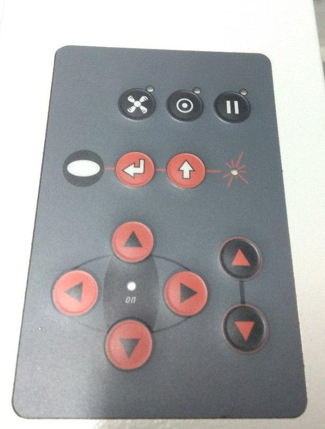
Using the Control Pad.
With the help of the control pad one can move the end effector to the desired position. The software will automatically
detect the position of the effector and it will display it on the computer screen. We can move the job to where the effector is
and it start to operate from that position.
Jogging the effector
Below is the first design I made using solidworks for the base structure.
Laser cut came out just fine and the fit was also perfect. This was a test cut though.
The next part needed was the shade. This was the tricky part. I wanted to create a structure that could bend.
This is called a living hinge, where you make some cuts on the sheet to make it bend. Designing the cuts was
fun but time consuming.
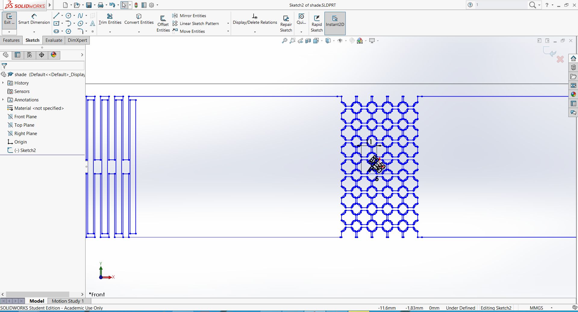
I used the Linear sketch pattern feature in Solidworks to design the cut.
Below is the Initial design I made.
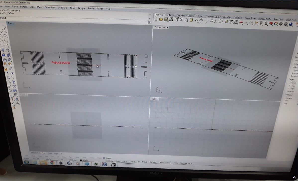
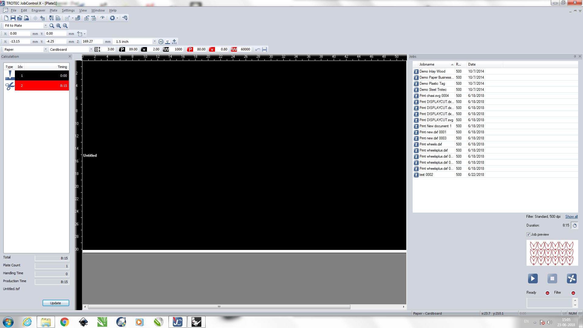
The file was imported to Rhino. The laser cutter engraves the entities that are black in color and cuts
the enities that are red in color. Using Rhino the colors were assigned to the entities.
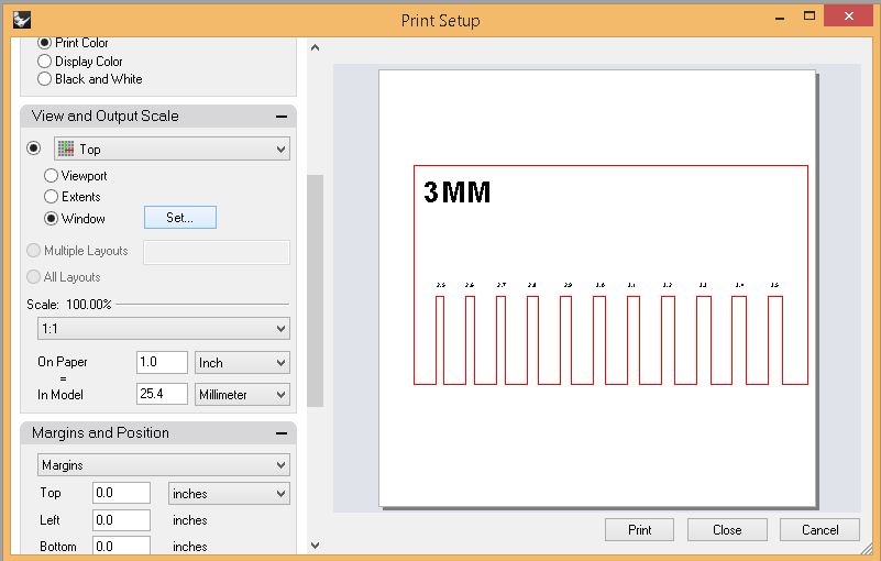
Once this is done we are required to set the print area in the print properties.
A rectangular area that just encloses the sketch entirely was made. Then the print option is
given which took me to the laser cutting software that shows the workspace. In this workspace the enclosed
sketch is pasted. The work appears like a grey box which can be moved around according to the user's wish.
This tool is handy when the workpiece available with us is of an irregular shape since it allows us to use
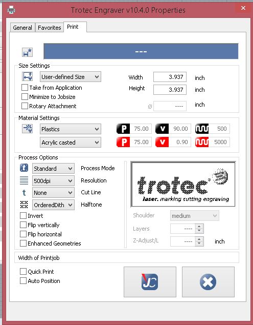
a particular portion of the workpiece. The material used for cutting is specified and the software automatically
chooses preset values for that material. Different materials require different cutting speed and frequency.
Result
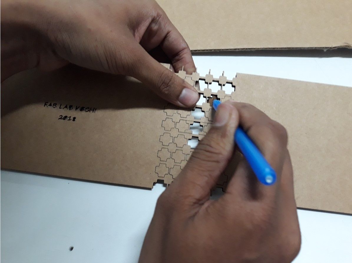
The cut was very precise and I had to used other tools to remove the cut part.
This design had a flaw. The cuts made in the shape of 'Plus' was symmetric and hence
it did not act as a living hinge but a very rigid structure. This is because the alternate
rows of the pattern had to be offset. Only then will it affect the integrity of the structure
This was a test cut and was a fail.
Rework
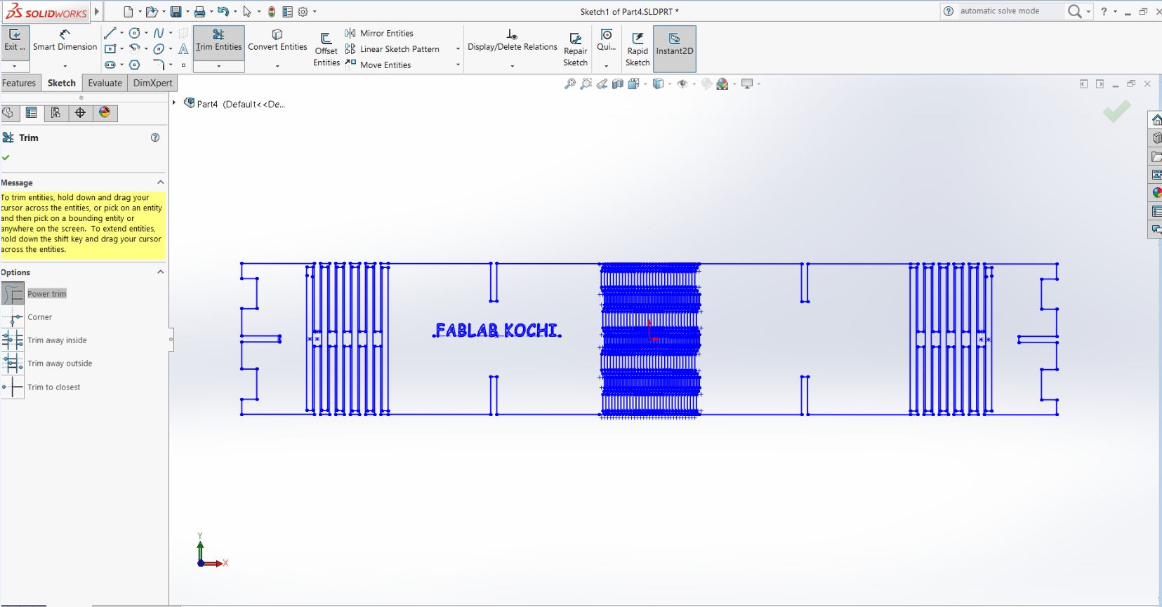
This time I had to keep in mind that the patterns drawn should be necessarily offset so that
it behaves like a living hinge.
This time I used a pattern as shown below. The Linear sketch pattern tool was used to achieve the
result.
This is the second design I made.
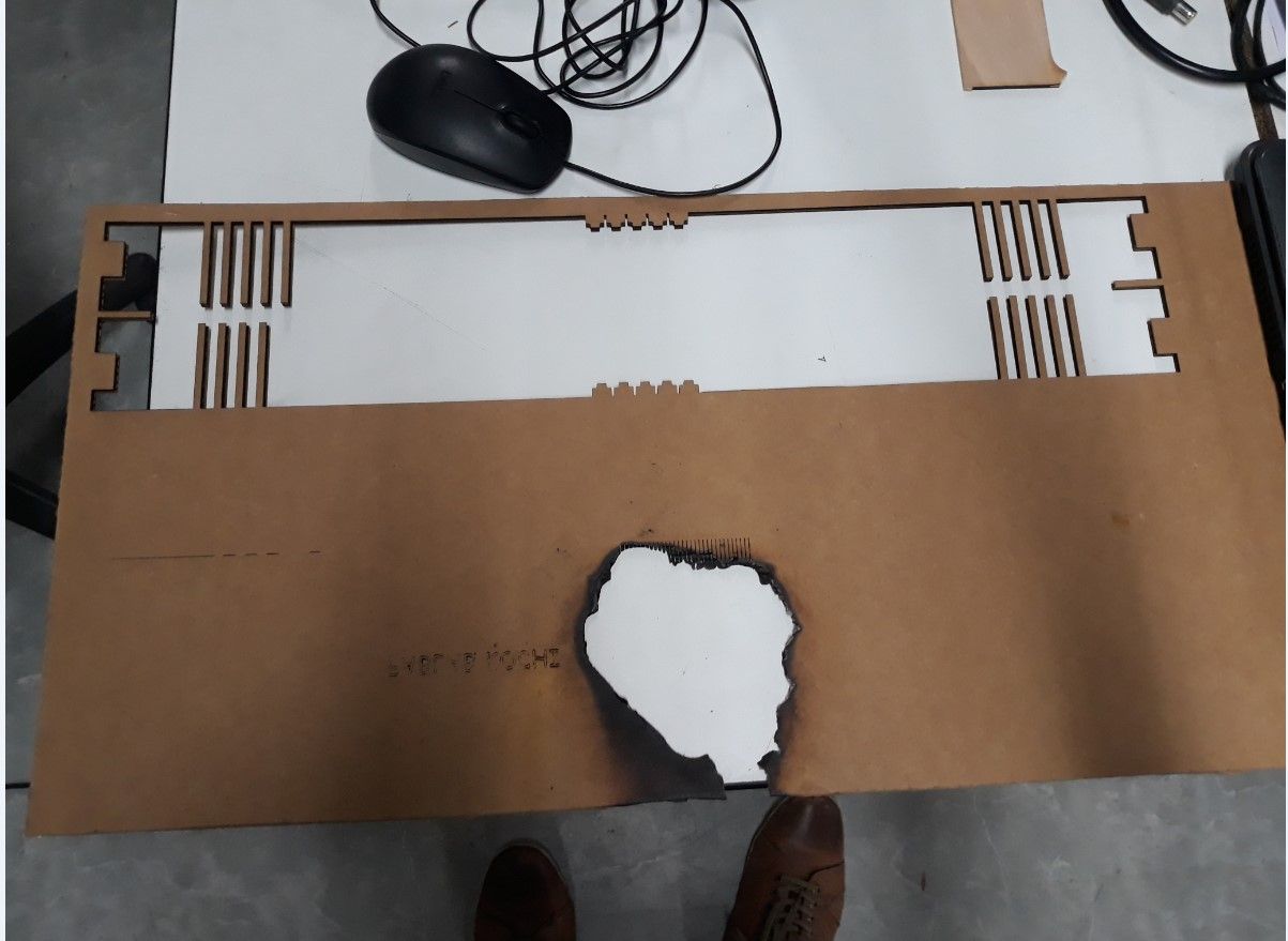
With this design the cut was made. But during the cutting process the Cardboard caught fire and the
process had to be stopped. I pressed the pause button , move the laser away from the fire and
removed the Cardboard immediately. This remnants were cleaned using a vaccum cleaner.
What actually happened
When analysed how the cardboard caught fire, my instructors helped be understand that the fault was
with the design. It caught fire when trying to make precise cuts that are placed very close together.
This resulted in a drastic increase in temperature and hence the fire. The curves I designed were made up
of many entities as against one single entity. Hence the machine made similar cuts very close to each other.
How the issue was solved
The issue was solved by making the curve a single entity. When the curve is made as a single entity the
machine will continue along the same path till the full cut is made. This gives sufficient time for cooling
purpose and the cardboard will not catch fire.
Rework 2
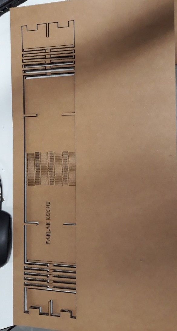
With all the necessary changes made the final cut was made. This time the cut was succesful. The new design
had allowed for sufficient cooling time and the material did not catch fire. The end result was refreshing
as this had taken me a really long time to do. Here are the images of the final cut piece.
The living hinge was perfect than I thought and had really good flexibility. However the cuts were very precise
and the parts were very delicate that I had to be really careful while taking out the parts. This was just the first
part of the total shade. Here are the images
Changing design to include more components
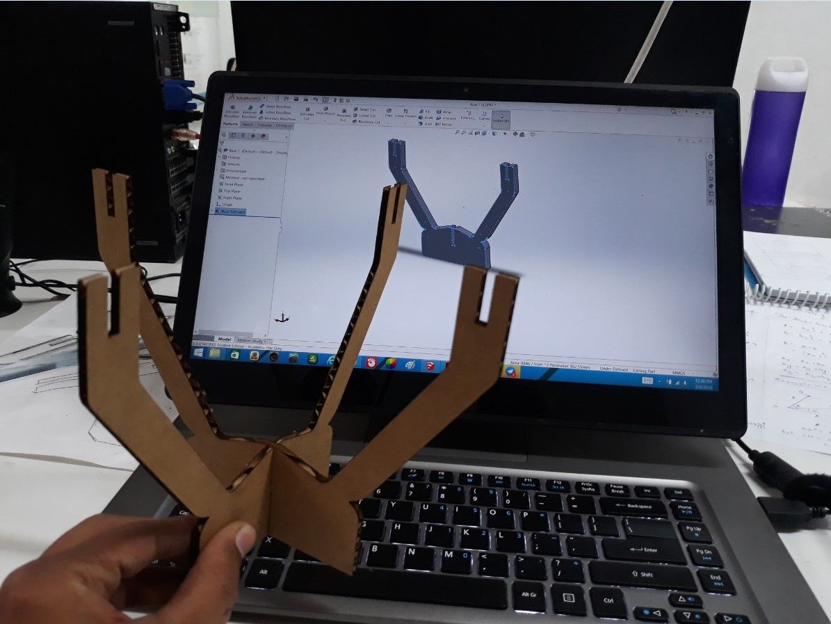
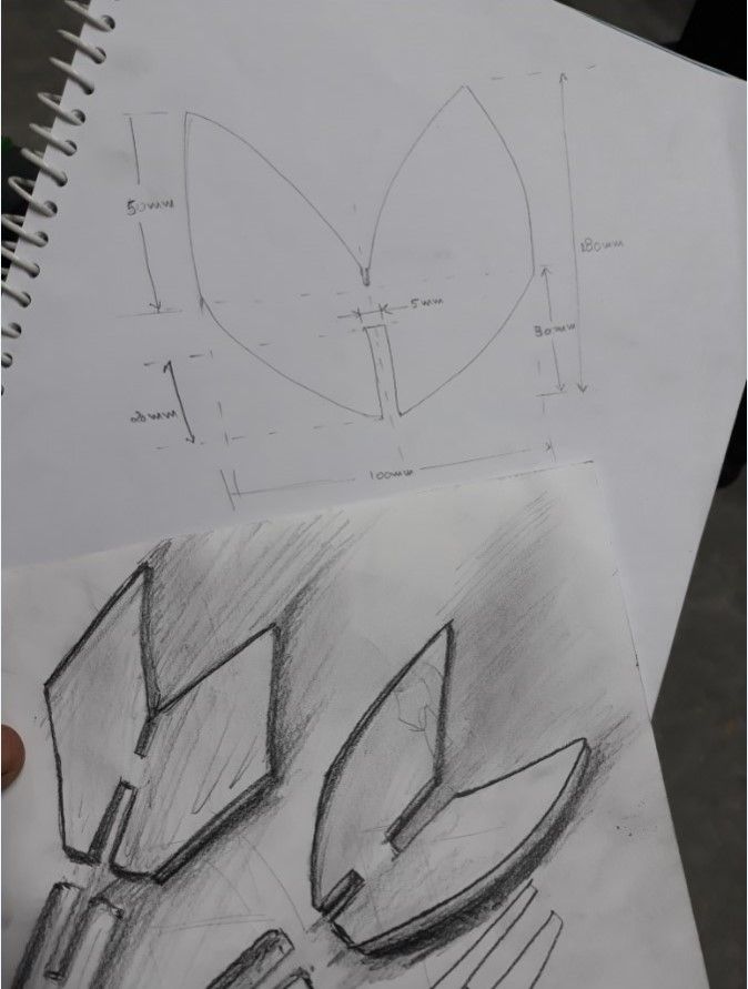
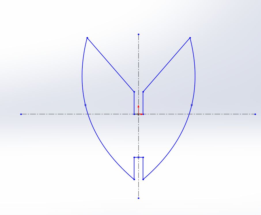
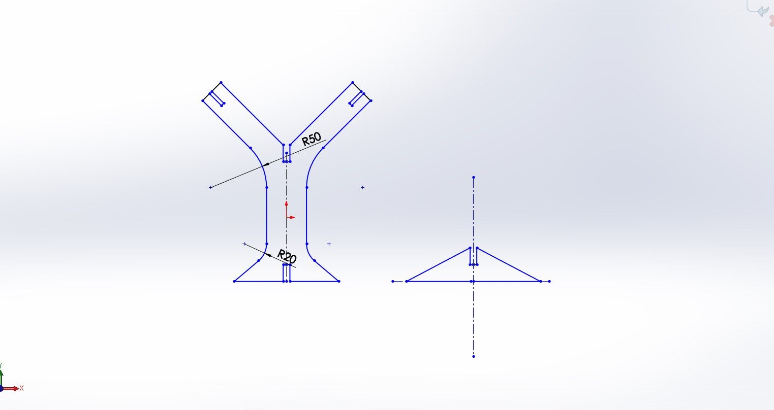
Getting a perfect fit with a living hinge was difficult. So I decided to change the design to make a tree.
The design was made using solid works.
Setting the parameters
Power- 80
Speed- 0.80
Frequency- 60000
Click on link below to download the design files leaf base
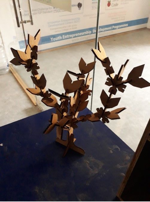
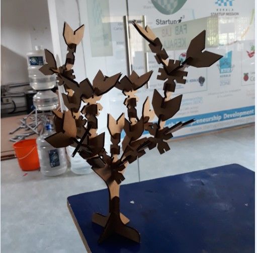
Final Product
Assembling all the components, a beautiful looking tree was made.
Group Assignment
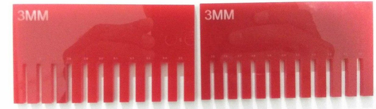
Understanding Kerf Scale
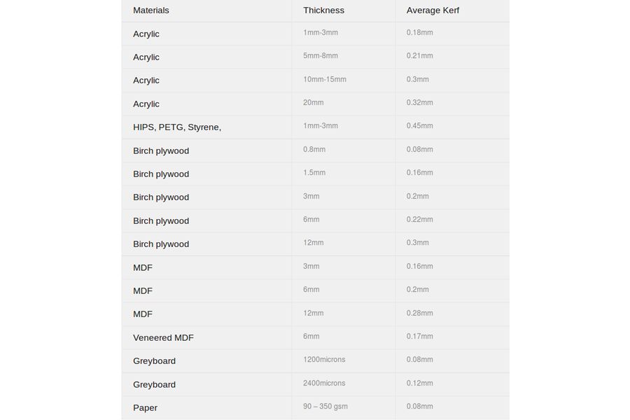
Kerf is the width of material that is removed by a cutting process. The laser beam burns a negligible portion
of material when it cuts the material. This is known as Laser Kerf. The laser kerf ranges from 0.08mm to 0.45mm, it is
depending on the type of material and other conditional factor.
Slot thickness= (material thickness) - (laser kerf of material)
source from http://www.cutlasercut.com/resources/tips-and-advice/what-is-laser-kerf
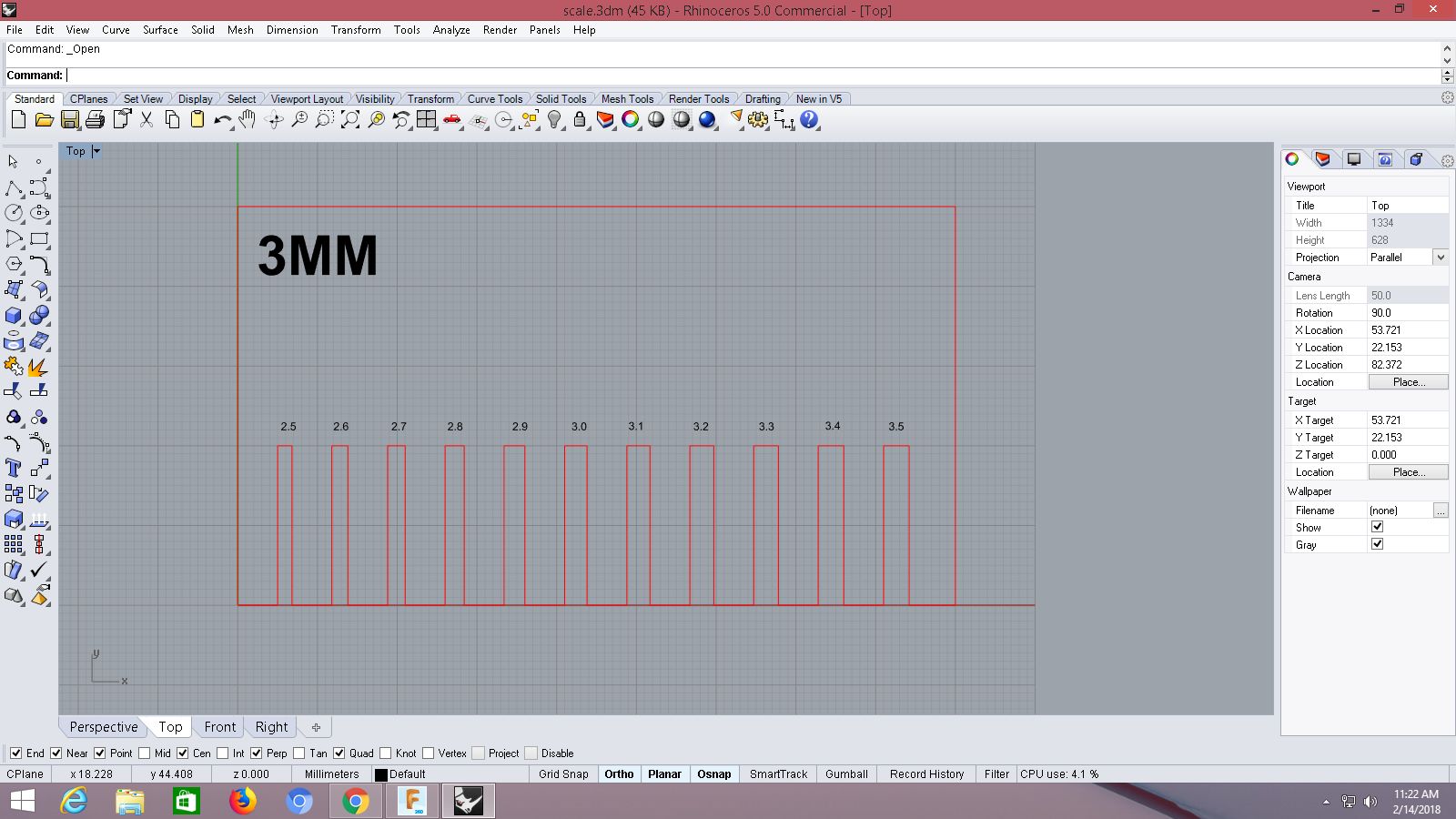
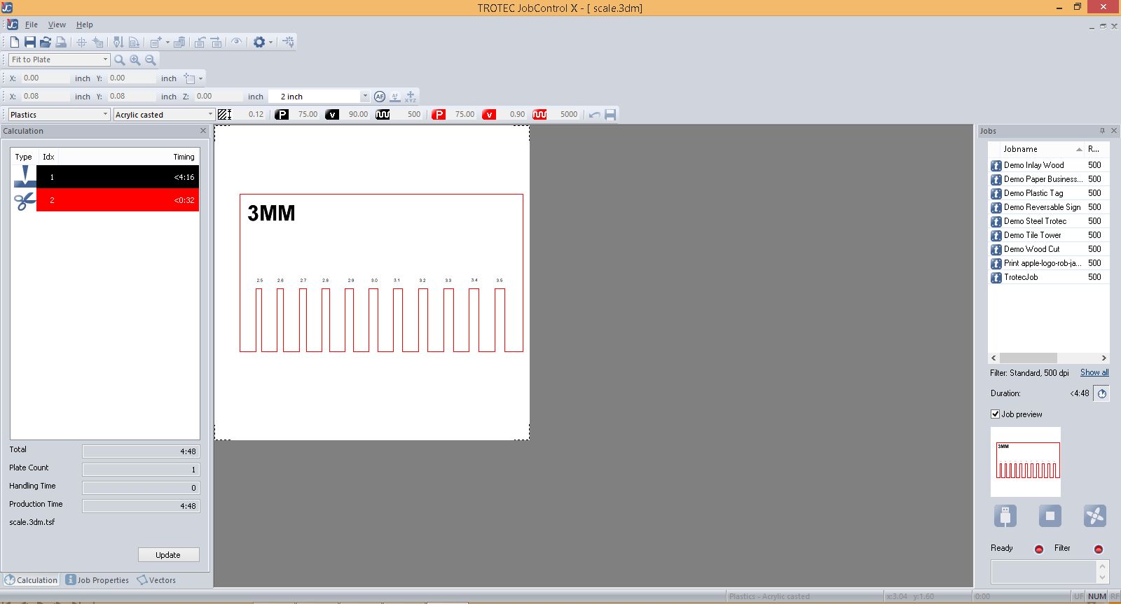
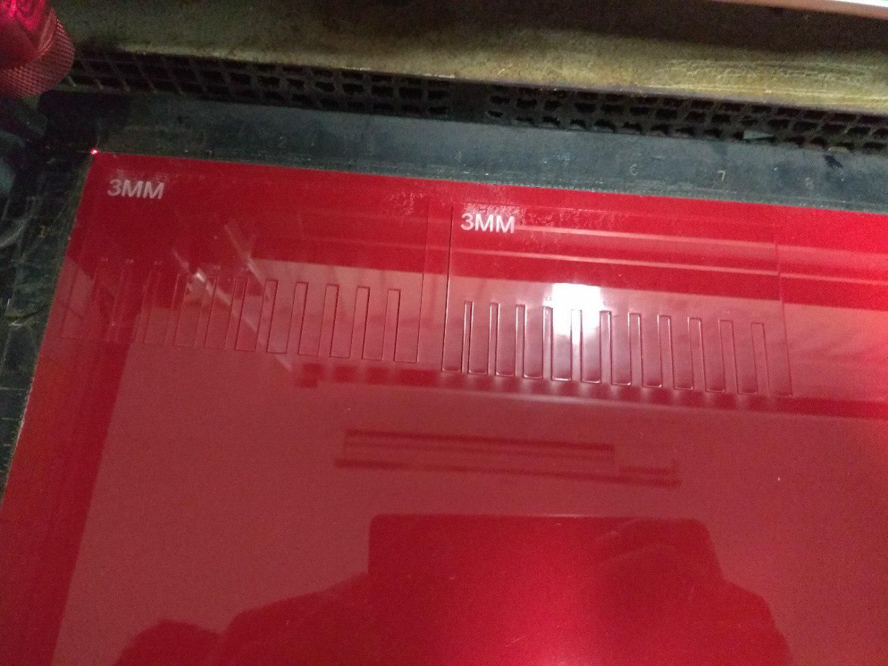
We then designed a kerf scale for 3mm Acrylic sheet. The design was made using Rhino.
Select the design, set the print area and send the file to trotec using print command