Electronic Production
This week is dedicated towards learning about Electronic production.
Prof. Neil talked us through PCB milling, soldering components and techniques
He suggeested we build an ISP board and program it. This was completely
new to me since I'm new to electronics.
The design was already available in the fabacademy site.
Fab ISP
In-system programming (ISP), also called In-Circuit Serial Programming (ICSP),
is the ability of some programmable logic devices, microcontrollers,
and other embedded devices to be programmed while installed
in a complete system,
rather than requiring the chip to be programmed prior
to installing it into the system. --wikipedia--
Fab-ISP is an in-system programmer for AVR microcontrollers,
which can be developed with in a fablab. This allows us to program
microcontrollers on other boards using a 6 pin IDC cable.
Programming is done through
avrdude.
We are using ATtiny45 chip in this ISP.
Below is the desing provided
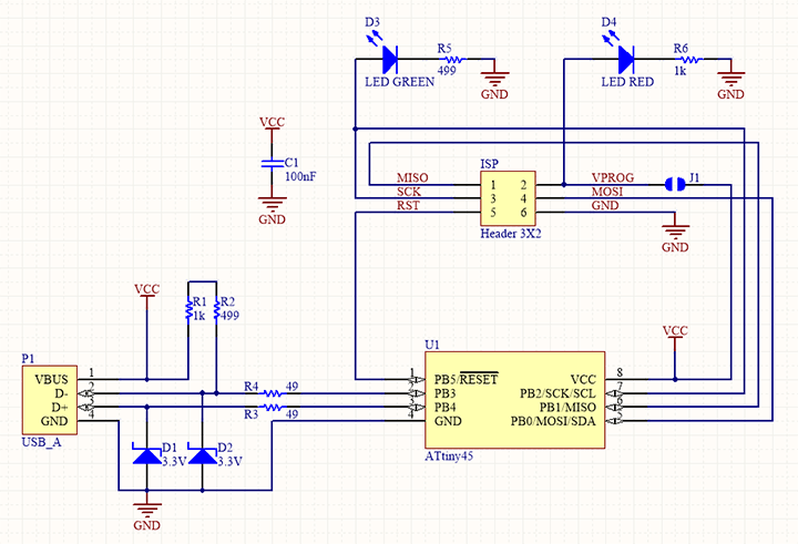
ISP Schematic
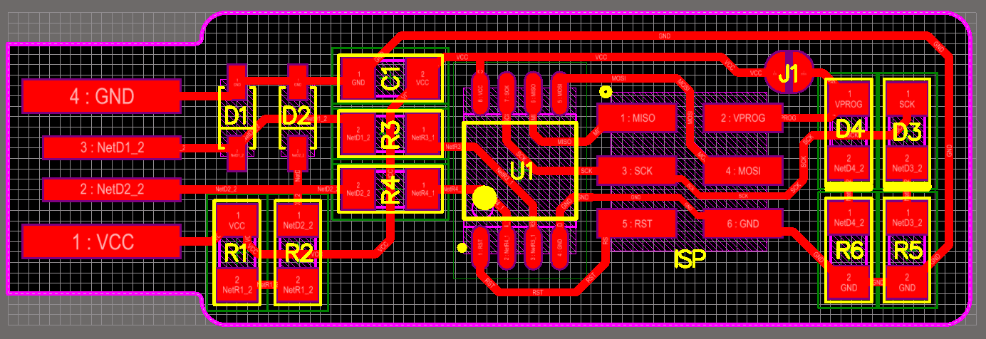
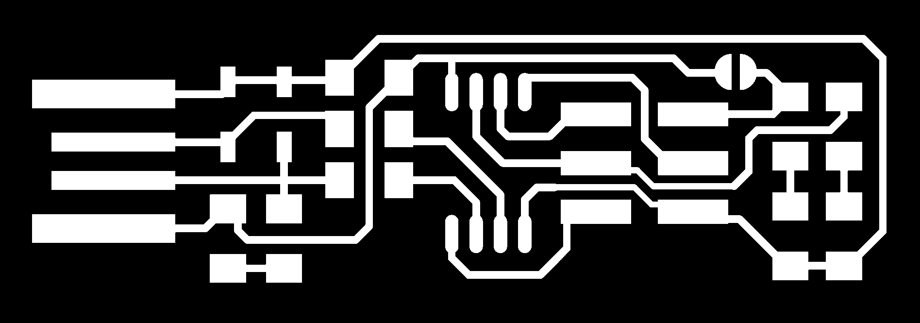
Trace Images
Cutout Images

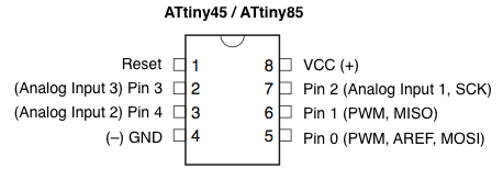
ATtiny45
For the production of the programmer we use ATtiny45 microcontroller.
ATtiny 45 is a small and cheap microcontroller that can be used for
for running simple programs. It has eight legs with 6 general purpose I/O
lines and 4KB of flash memory.
Pin Out Diagram
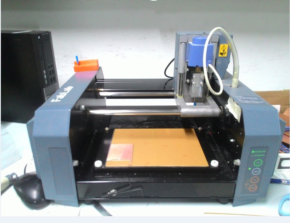
Roland Modella 3D plotter
Roland Modella MDX-20 is a desktop CNC machine used
for making PCBs, carving moulds with soft materials like wax and
can also be used for scanning 3D models of objects.
The detachable
base plate moves along Y axis, the header where the driller is mounted moves along X axis and
the carriage where the motor is attached moves along the Z axis.
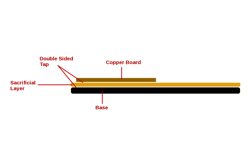
Setting up the machine
The machine has a metal base which moves. Our PCB is placed on this base.
The bit usedd for milling and cutting operations and very delicate.
If the bit comes in contact with the metal plate,there are chances that the
bit get damaged hence a sacrificial layer is placed on top of the
metal plate and our PCB is placed on the top of this layer and held in position
using a double sided tape.
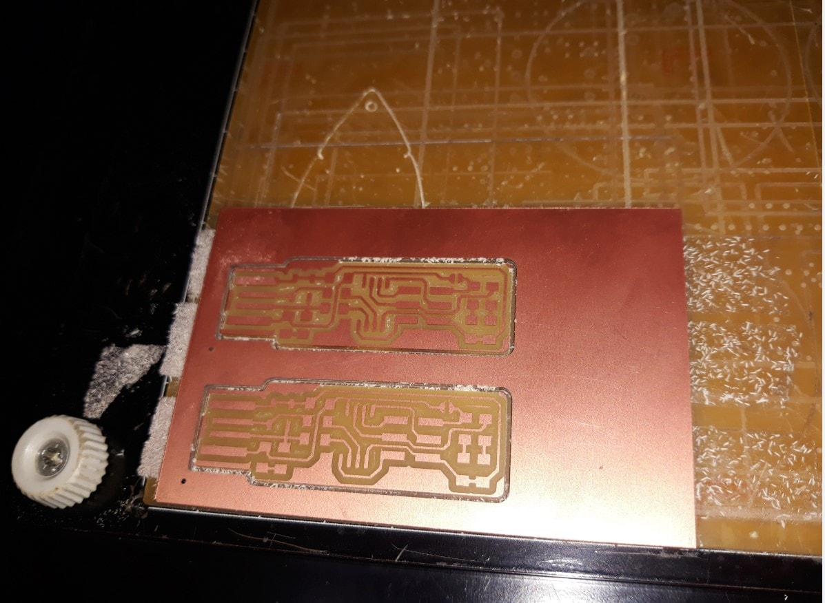
Making the PCB
For making the PCB we perform both milling and cutting. Different bits are used for
achieving these purposes. Milling operation is carried out first.
- Milling
For milling operation drill bit of 1/64 is used. Below are the step by step
operations that are carried out.
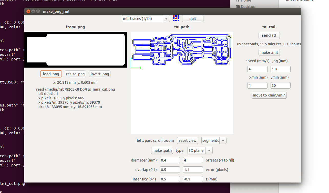
- Open Fab module using the command fab and select 'png' in the input format
and 'Roland MDX-20 mill' in 'output process' boxes.
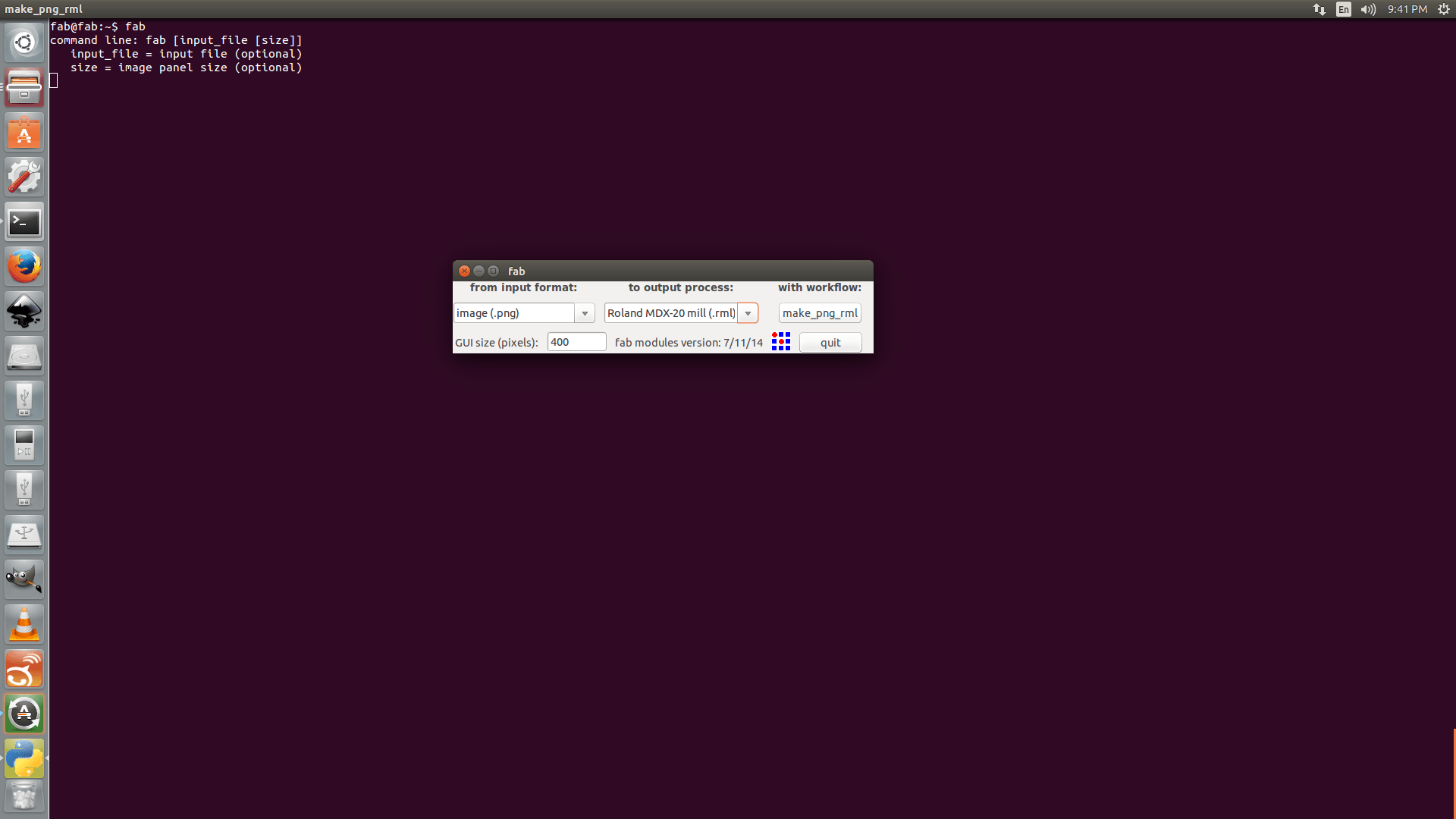
- Load mill image to the software and click on make path
button to draw paths. Adjust X and Y positions of driller using
Xmin and Ymin options in thw window. To adjust the Z axis, use UP & down
buttons on the Modella Machine.

-
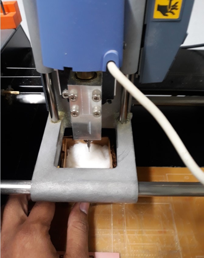
The bit has to be adjusted such that it just touches the board. For this
the bit has to be loosened using allen key. Special care has to be taken
while removing the bit. It should be made sure that the bit does not fall
down to the base while changing as this impact can easily break the tip
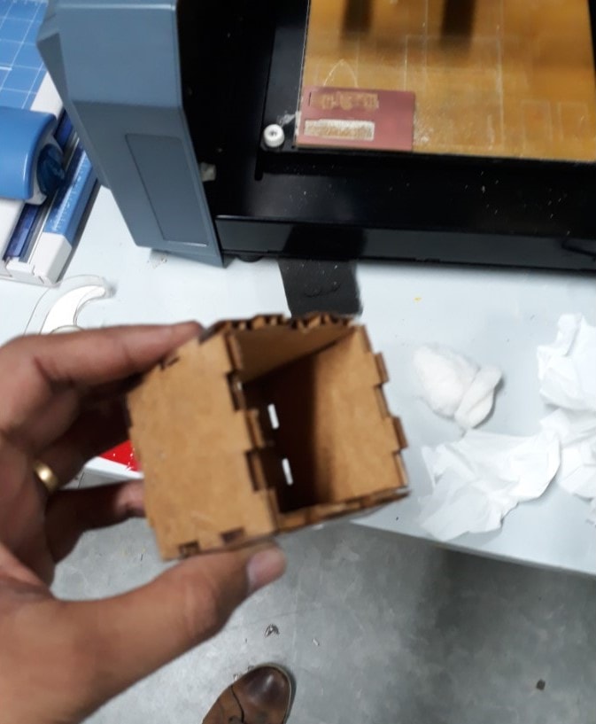
- I decided to make a Safety drop box(as i would like to call it) to make the bit
removal process a little more safer. I used some unused laser cut cardboard pieces
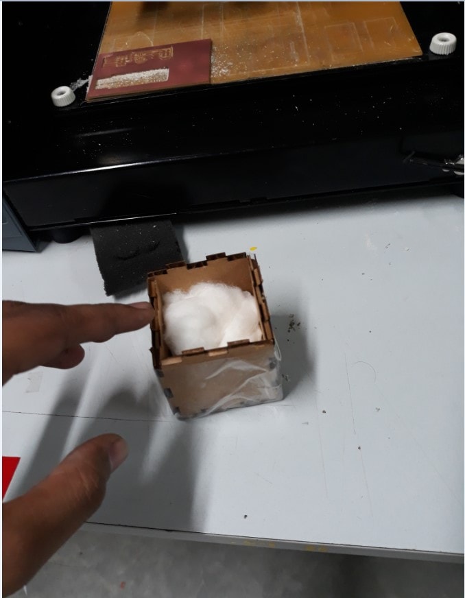
to make a box out of it. I then filled the box with cotton and tissue paper. This box is
now placed under the bit during its removal process so that even if the bit drops, it's
tip is not broken.
-
Select mill bit size as 1/64 from select box. Now click on make.rml
button and then send it button, then click on Begin Milling
on the new window opened. Now the machine will start milling. The total
time taken is diplayed on the screen.
-
Next step is cutting. The steps involved are same as that mentioned above,
however this time the bit has to be changed to Cutting bit 1/34.
Move the header up using Up button on modella machine menu.
Bring the bit to initial point like we did previously and change the bit
Then bring the header down using Down button, so that there is some distance between the bit and the copper plate.
Now adjust the bit such that it touches the board and tighten the screw using allen key.
Load the new image for cutting.
Final outcome
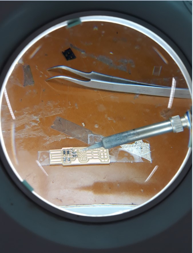
Soldering
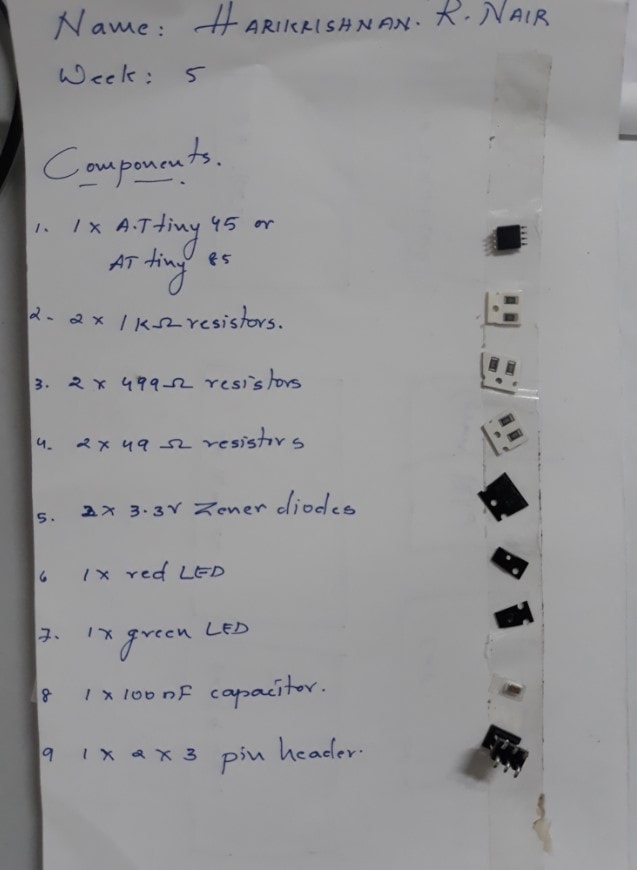
Now the next thing is to solder the components on to the board. As the
instructors suggested I wrote the component names on a sheet of paper
and stuck the components onto the sheet before starting the soldering.
This method is helpful in preventing the components from getting mixed up
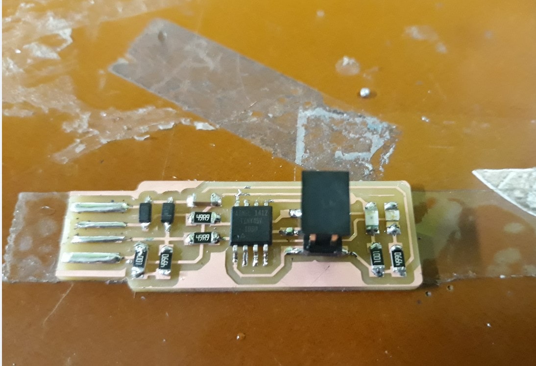
Final product
Programming the ISP
After succesful completion of the ISP fabrication the next step is to install
necessary modules.
For installing the modules,use the code - sudo apt install avrdude gcc-avr avr-libc make
The firmare was available in the fabacdemy site. I downloaded it and moved
it to folder.
For burning the firmware into the chip another programmer is used. The programmer
is connected to the PC via usb port and the ISP is connected to the programmer
using IDC cable.
Below are the steps for burning the firmware to the ISP.
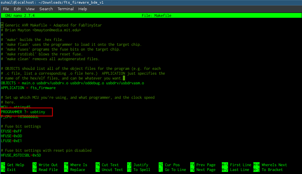
- Go to the firmware directory and check if Makefile contains 'PROGRAMMER',
as 'usbtiny'.
-
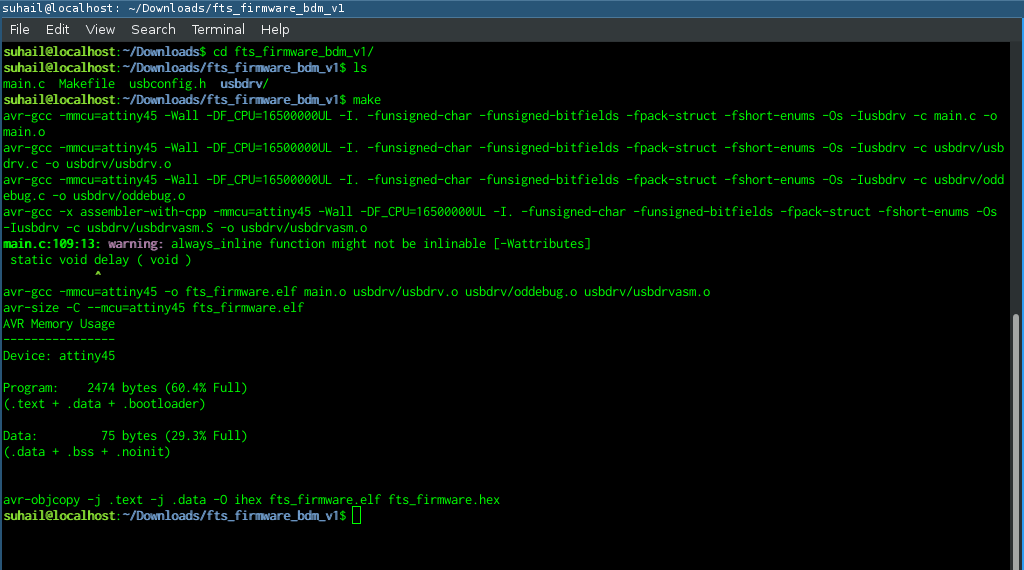
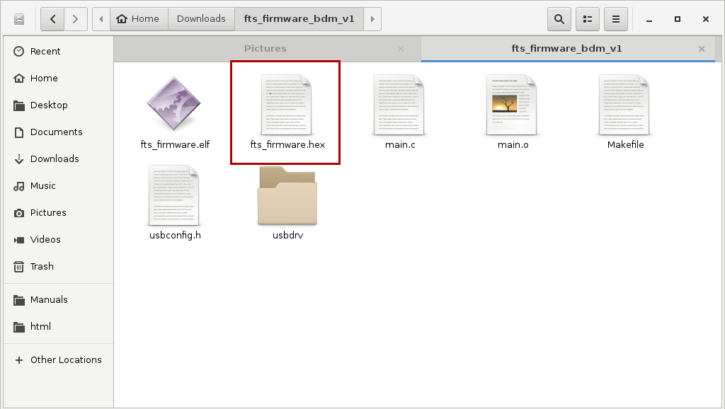
Run make command to generate hex file. After running this command, our
directory now contain a file named fts_firmware.hex.
-
Run make flash to flash hex file to the chip. Use code
sudo make flash
-
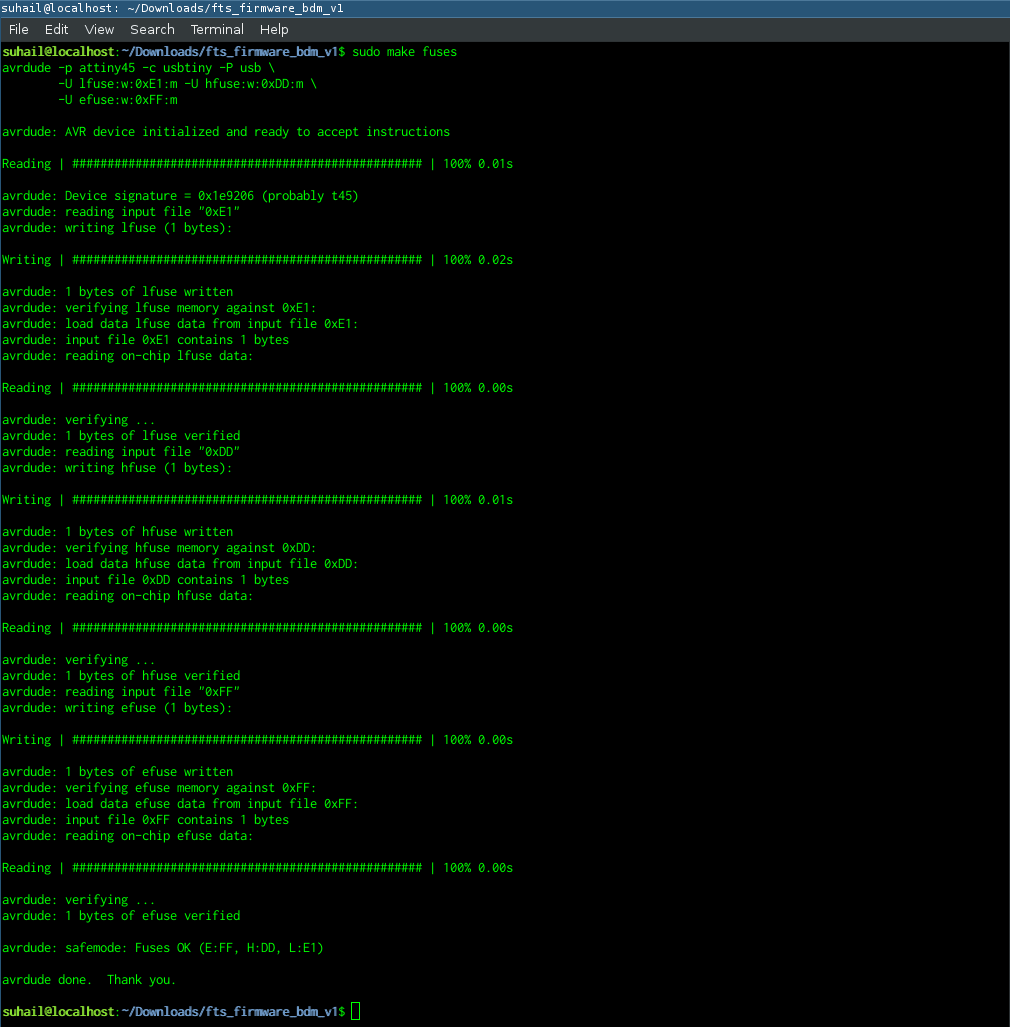
Run make fusesto setup the fuses. Use code
Testing
For testing the ISP,I removed the ISP from the programmer and connected it
directly to the PC. The LED turned on. Now, to check if the system is detecting
detecting the USB device, I used the lsusb command.This should list
all the usb devices connected. dmesg command might be useful to
check if there are any issues with the device.
This command prints kernal messages.
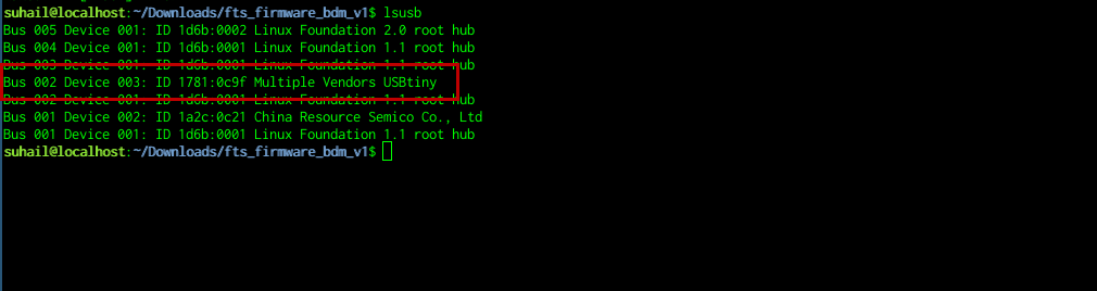
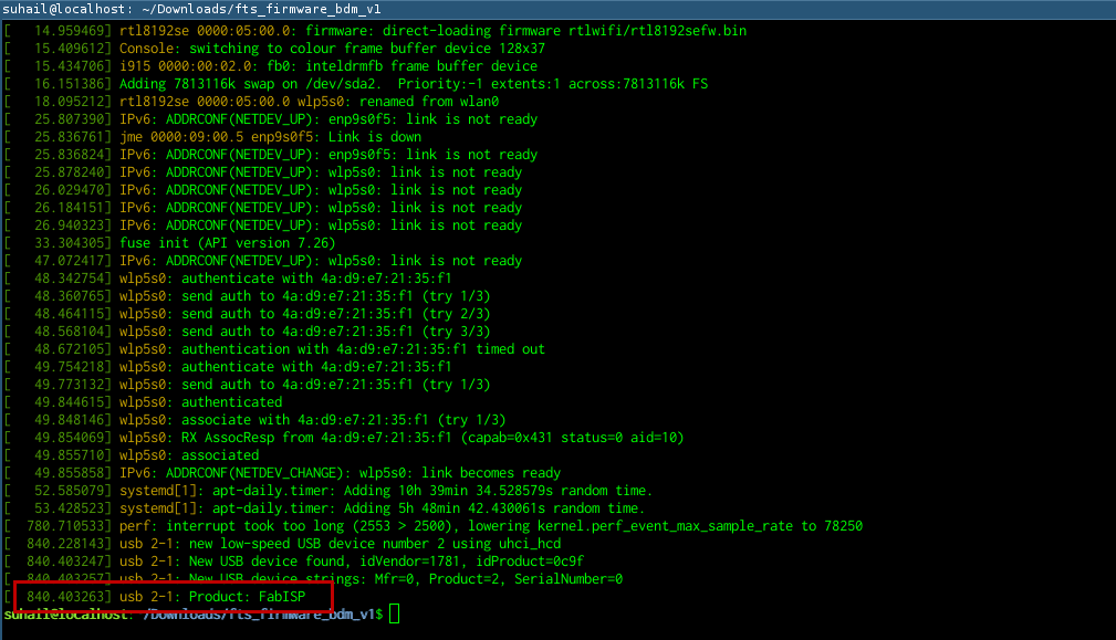
The ISP has been succesfully detected by the system. This means
that the ISP is working fine. Next step is to disable the reset pin
so that it can be used as an IO pin.
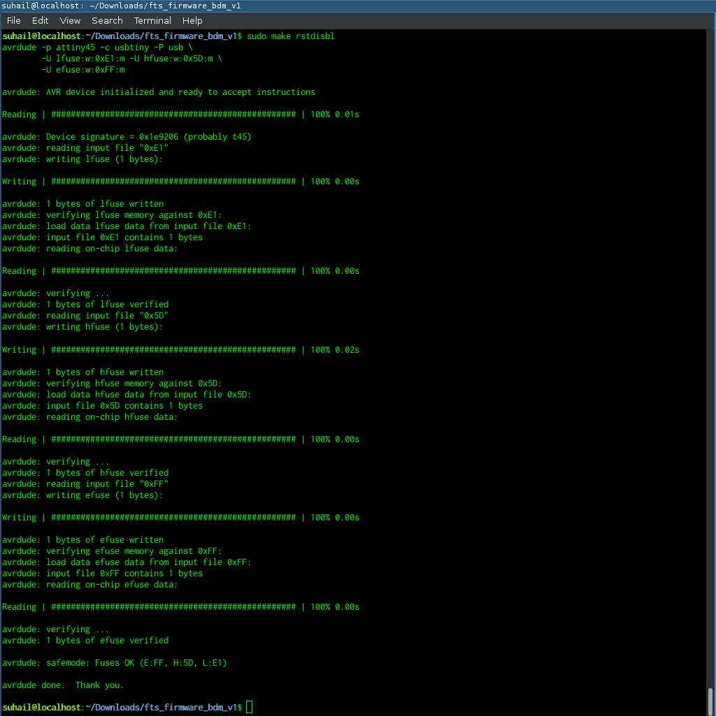
Disable Reset
To disable the reset pin run the command make rstdisbl. Use command
sudo make rstdisbl