Hari's Week 9
Embedded Programming
Things to do this week
- Group Assignment - Experiment with other architectures
- Individual Assignment- Read a microcontroller data sheet and program your board to do
something with as many different programming languages and programming
environments as possible.
Introduction
This week's assignment is to programme the Echo-Hello board that was designed
in the Electronics Design week. Coming from a mechanical engineering background
programming is something I'm not very well aquainted with. So this week
is a good oppurtunity for me to learn more about programming and it could be
my first step into the world of Electronic system programming.
Embedded systems
An embedded system is a computer system with a dedicated function within a larger mechanical or electrical system,
often with real-time computing constraints. It is embedded as part of a complete device often including
hardware and mechanical parts. Embedded systems control many devices in common use today.Ninety-eight percent
of all microprocessors are manufactured as components of embedded systems.
Microcontroller
A microcontroller (or MCU for microcontroller unit) is a small computer on a single integrated circuit.
A microcontroller contains one or more CPUs (processor cores) along with memory and programmable input/output peripherals.Microcontrollers are designed
for embedded applications, in contrast to the microprocessors used in personal computers or
other general purpose applications consisting of various discrete chips.
Microprocessor
A microprocessor is a computer processor which incorporates the functions of a computer's central
processing unit (CPU) on a single integrated circuit, or at most a few integrated circuits.
The microprocessor is a multipurpose, clock driven, register based, digital-integrated circuit which
accepts binary data as input, processes it according to instructions stored in its memory, and provides
results as output. Microprocessors contain both combinational logic and sequential digital logic.
Microprocessors operate on numbers and symbols represented in the binary numeral system.
Microprocessor Vs Microcontroller
Microprocessor is an IC which has only the CPU inside them i.e. only the processing powers such as Intel’s
Pentium 1,2,3,4, core 2 duo, i3, i5 etc. These microprocessors don’t have RAM, ROM, and other peripheral on the chip.
A system designer has to add them externally to make them functional. Application of microprocessor includes Desktop PC’s, Laptops, notepads etc.
But this is not the case with Microcontrollers. Microcontroller has a CPU, in addition with a fixed amount of RAM,
ROM and other peripherals all embedded on a single chip. At times it is also termed as a mini computer or a computer on a single chip.
Today different manufacturers produce microcontrollers with a wide range of features available in different versions. Some manufacturers are ATMEL,
Microchip, TI, Freescale, Philips, Motorola etc.
Architectures
Von Neumann Architecture
The Von Neumann architecture was first proposed by a computer scientist John von Neumann.
In this architecture, one data path or bus exists for both instruction and data. As a result,
the CPU does one operation at a time. It either fetches an instruction from memory, or performs
read/write operation on data. So an instruction fetch and a data operation cannot occur simultaneously,
sharing a common bus.
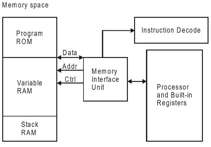
Von-Neumann architecture supports simple hardware. It allows the use of a single, sequential memory.
Today's processing speeds vastly outpace memory access times, and we employ a very fast but small
amount of memory (cache) local to the processor.
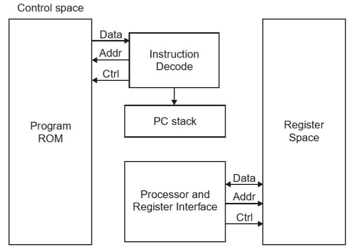
Havard Architecture
The Harvard architecture offers separate storage and signal buses for instructions and data.
This architecture has data storage entirely contained within the CPU, and there is no access to
the instruction storage as data. Computers have separate memory areas for program instructions and
data using internal data buses, allowing simultaneous access to both instructions and data.
Programs needed to be loaded by an operator; the processor could not boot itself.
In a Harvard architecture, there is no need to make the two memories share properties.
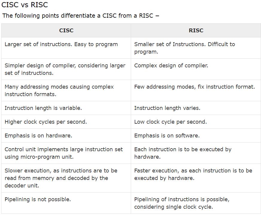
CISC and RISC
CISC is a Complex Instruction Set Computer. It is a computer that can address a large number of instructions.
In the early 1980s, computer designers recommended that computers should use fewer instructions with simple
constructs so that they can be executed much faster within the CPU without having to use memory. Such computers
are classified as Reduced Instruction Set Computer or RISC.
Echo Hello Board
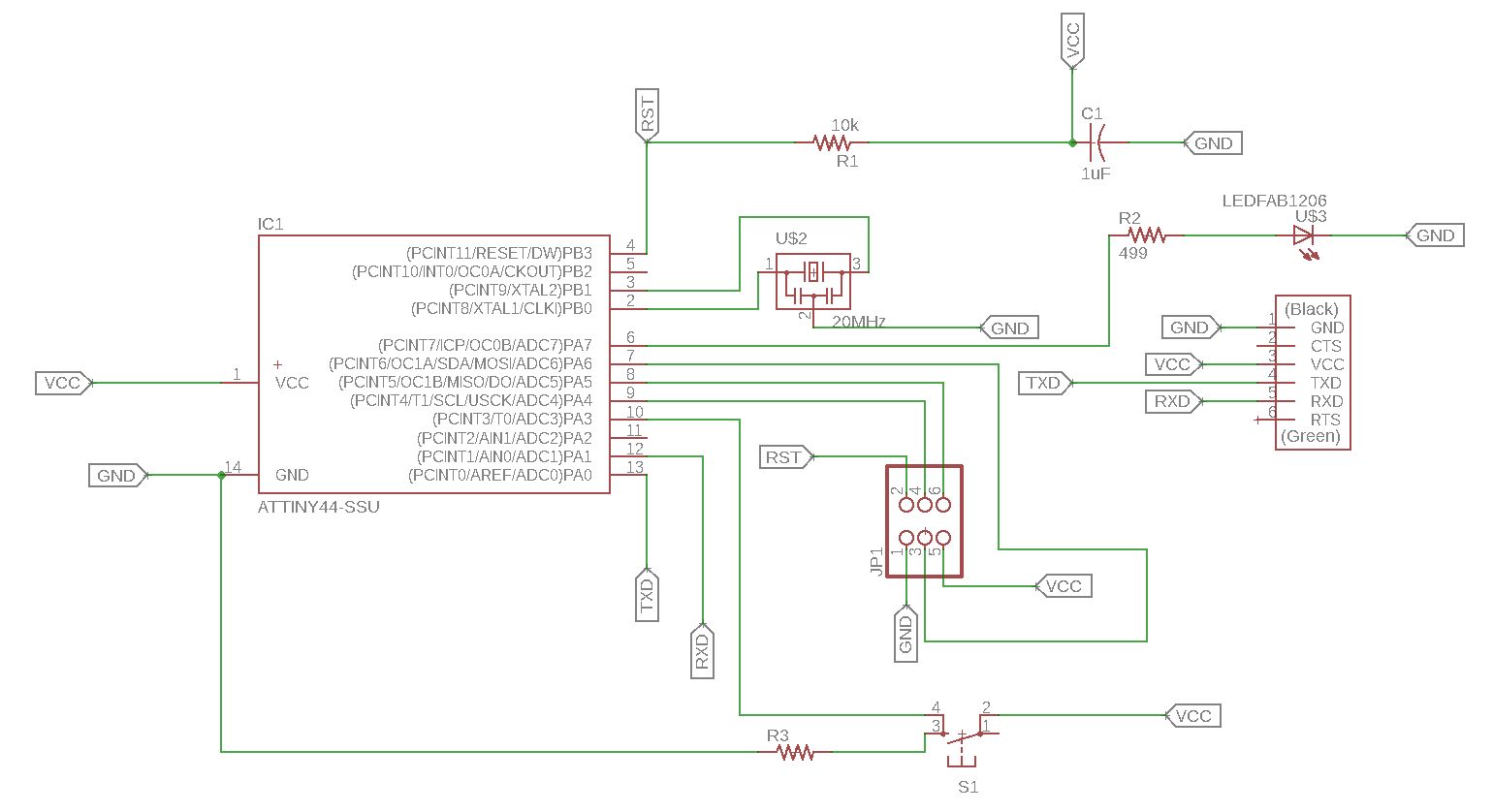
This is the Schematic of the board that I had designed last week. The assignment
for this week is to program this board using various programming languages.
I'm starting my programming with Arduino.
The echo hello board uses an ATtiny44 microchip. It's a 8-bit RISC based microcontroller.
The Originla Design have only the UART Port and I added e a Programmable Button connected to pin PA3 with a Pull-down Resistor
and LED connectd to PA7. A 20Mhz external resonator is also added.
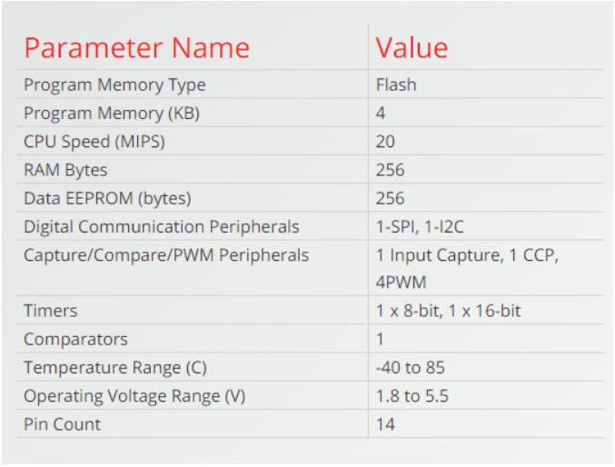
ATtiny 44A
It's a low power AVR® 8-bit microcontroller based on the RISC architecture.It have 12 GPIO pin's.
ATtiny24A/44A/84A are low-power CMOS 8-bit microcontrollers based on the
AVR enhanced RISC architecture. By executing powerful instructions in a single
clock cycle, the ATtiny24A/44A/84A achieves throughputs approaching 1MIPS per
MHz allowing the system designer to optimize power comsumption versus processing
speed.
Here is the datasheet of the microcontroller which will help better in understanding
about the microcontroller.
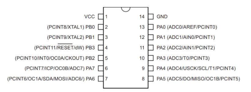
PIN Descriptions
-
VCC
Supply Voltage
- GND
Ground
- Port B(PB3...PB0)
Port B is a 4-bit bi-directional I/O port with internal pull-up
resistors (selected for each bit). As inputs, Port B pins that
are externally pulled low will source current if the pull-up
resistors are activated.so we don't need to
add a pull-up resistor externaly for button's and other purpose.
- RESET
Reset input. A low level on this pin for longer than the minimum pulse length will generate a reset, even if the clock is not running.
A reset will just reset the program that is currently runnig .
- PortA(PA7..PA0)
Port A is a 8-bit bi-directional I/O port with internal pull-up resistors (selected for each bit).
As inputs, Port A pins that are externally
pulled low will source current if the pull-up resistors are activated
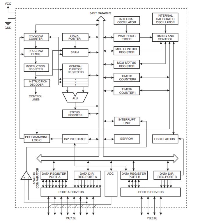
Block Diagram
Programming the board
This week I have to try various programming methods to program the echo hello
board. The easiest tool I prefer is Arduino IDE
Arduino Code
Learning the code for Arduino was comparatively easy. There are two
sets of code in Arduino, setup and loop
The instructions in the setup is what is going to be executed
and what is in the loop will be repeat continuosly.
For example, here the instruction in the setup is to specify that
the pin PA7 is the output and the instruction in the loop is to blink
the LED continuosly after every one second
Arduino Code
    void setup() {
    {
      pinMode(PA7,output);
    }

    void loop()

    }
    digitalWrite(PA7, HIGH);
     delay(1000);
     digitalWrite(PA7,LOW);
     delay(1000);
    }
Atmel Studio (GCC C)
Atmel Studio is the integrated development platform (IDP) for developing and debugging all AVR® and SAM microcontroller applications.
The Atmel Studio 7 IDP gives you a seamless and easy-to-use environment to write, build and debug your applications written in C/C++ or assembly code.
It also connects seamlessly to the debuggers, programmers and development kits that support AVR and SAM devices. (source:- microchip offical page).
In embedded c we need handle the registers.Each of the AVR Digital I/O ports is associated with three (3) I/O register.
A Data Direction Register (DDRx), A Pin Register (PINx) and a Port Register (PORTx). Where x is the port A, B, C, etc.
DDRx - Port X Data Direction Register

DDRx is an 8-bit register which stores configuration information for the pins of Portx. Writing a 1 in the pin location in the DDRx makes the physical pin of that port an output pin and writing a 0 makes that pin an input pin.
Note: Each physical pin of a port is configured independently and thus a port can have some of its pins configured as input an the others as output pins.
PINx - Port X Input Pins Register

PINx is an 8-bit register that stores the logic value, the current state, of the physical pins on Portx. So to read the values on the pins of Portx, you read the values that are in its PIN register.
PORTx - Port X Data Register

PORTx is an 8-bit register which stores the logic values that currently being outputted on the physical pins of Portx if the pins are configured as output pins. So to write values to a port, you write the values to the PORT register of that port..
In Atmel Studio we are writing C code. In order to use the Atmel Studio with our Fab ISP we need to configure the studio before use.
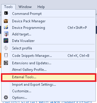
- Debug Verison
Title:- USBTiny ISP Debug.
Command :- avrdude.exe
Arguments :- -c usbtiny -p attiny44 -U flash:w:$(ProjectDir)Debug\$(TargetName).hex:i
click apply and ok to save the tool.
- Release Verison
Title:- USBTiny ISP Release.
Command :- avrdude.exe
Arguments :- -c usbtiny -p attiny44 -U flash:w:$(ProjectDir)Release\$(TargetName).hex:i
click apply and ok to save the tool.
Clickhere to download avrdude
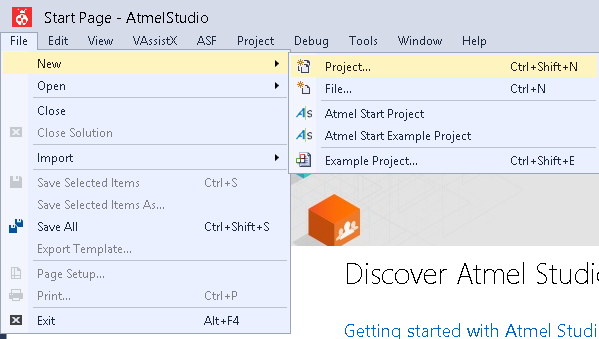
- Start a Project by clicking File >> New >> Project
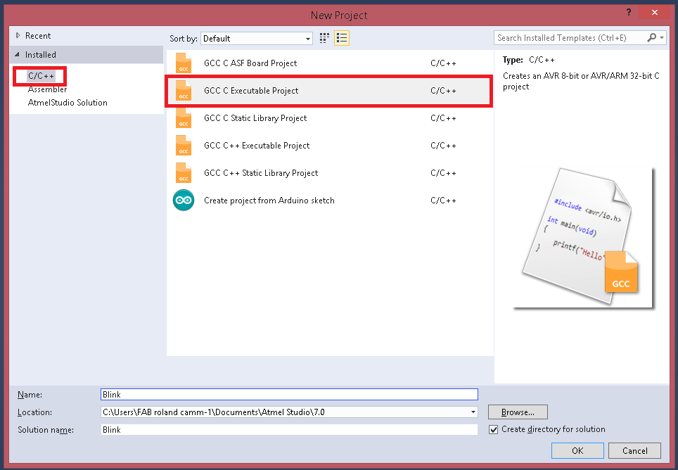
- select C/C++ as language and Template as GCC C Executable Project give a name and click OK.
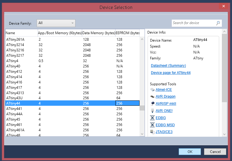
- Select the Target Microcontroller , in here we have ATtiny44.
Code using C
Arduino Code
    #define F_CPU 20000000UL      //Clock 20-Mhz
    #include <avr/io.h>
    #include <util/delay.h>

    int main(void)
    {

      DDRA |= (1 << 7);      //Set PA7 as OUTPUT


      while (1)
      {

        PORTA = PORTA | (1 << 7); // set PA7 as HIGH(ON)
        _delay_ms(1000);
        PORTA &= ~(1 << 7);   //set PA7 as LOW (OFF)
        _delay_ms(1000);
      }

    }
The output for this code is the same as shown in the video above as we are only blinking an led