
Week Thirteen
Assignment
What I did
Introduction
This week Neil gave us an introduction to Interfacing and application programming and different methods to create apps like the MIT App Inventor.My idea was to develop an android app for controlling the LED on a board that I've made in the input week via Bluetooth.
Basics
MIT App inventor is an easy to use application developer. There are mainly two parts in an MIT App Inventor Designer and Blocks in which the Designer part deals with the user interface and the Blocks deal with the logic part of the app.Watch the below video tutorial to get an idea about the App Inventor Programe
Making the App
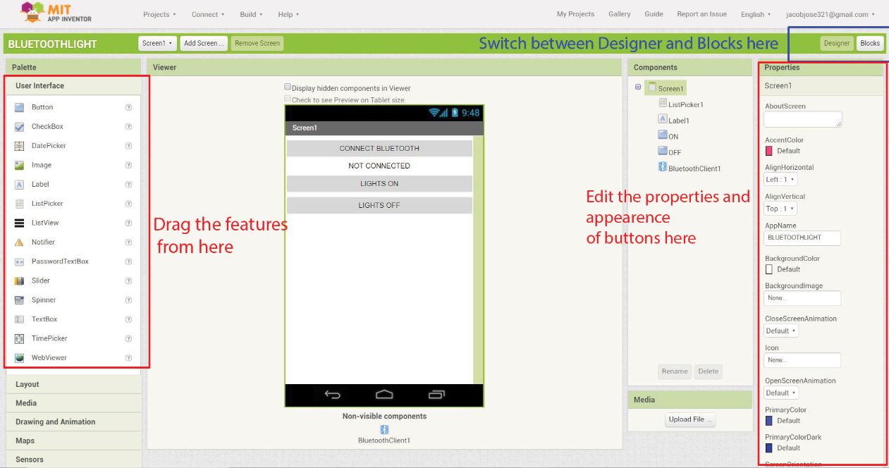
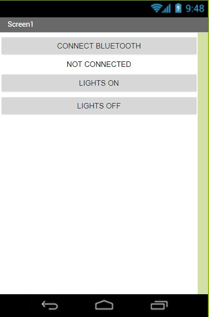
To start using the MIT App Inventor we have to first go to http://ai2.appinventor.mit.edu and login with our gmail account.As mentioned earlier we have two main parts called Designer and Block to start making our app. In our designer part we can speacify the overall outlook of our app. We can determine the color shape and other details of the user interface. In my case I had mainly 3 buttons LIGHTS ON , LIGHTS OFF and CONNECT BLUETOOTH. We can simply drag and drop these buttons and edit the details to our required speacifications. I used Listpicker to list all the bluetooth devices and LIGHT buttons to control them.
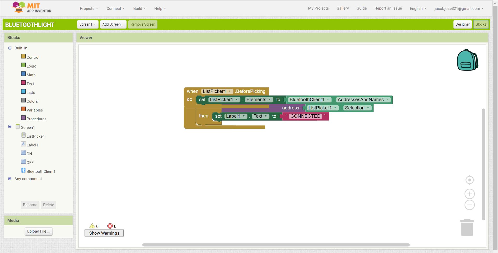
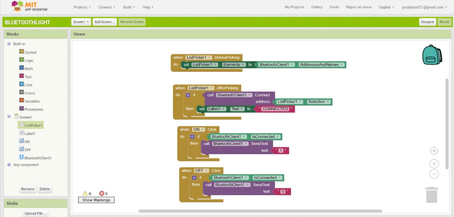
The logic of the apps can be set in the Block region by simply dragging and dropping different blocks accordingly.
For listing all the bluetooth devices I used the listpicker option.Now the logic can be applied to each designer block by going to the block window.
The final step towards making your first android app is to export the apk file. There are two options, either you can scan the QR code download the app directly from your mobile phone or you can download it to your PC. I downloaded the apk file directly to my mobile phone.
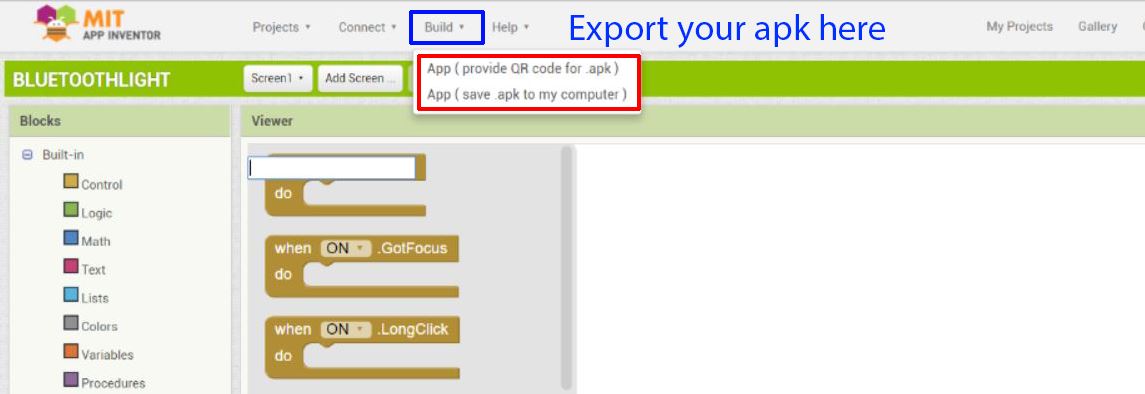
Download the apk files here .
Hardware settings
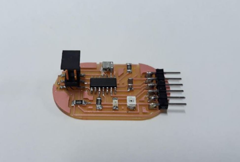
For this weeks assignment I'll be using the photo transistor board that I've made in the input week since it has an LED and a UART port.
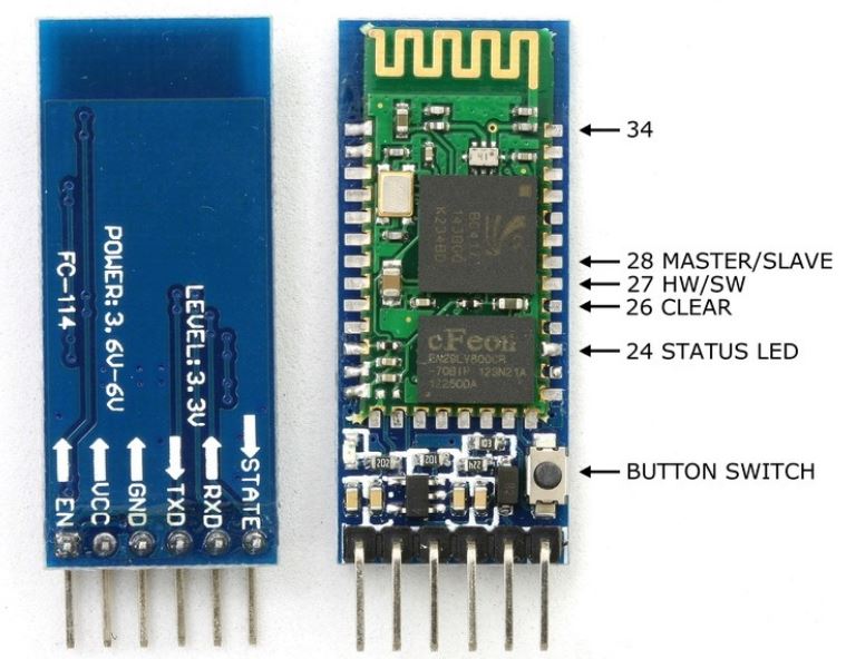
For bluetooth connectivity I'll be using the HC-50 Bluetooth Module .
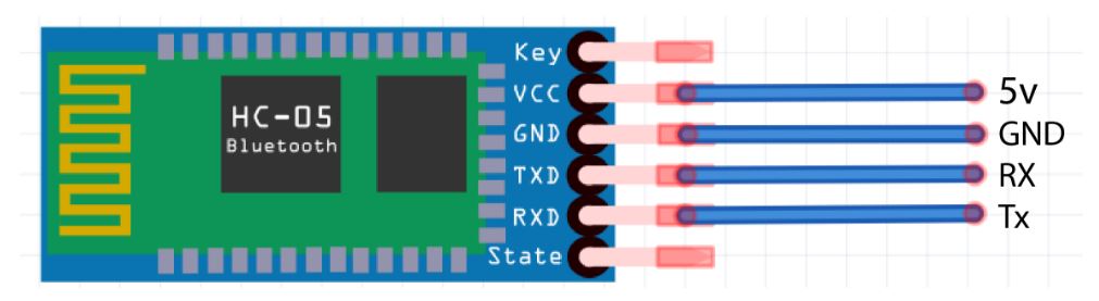
By the above connection setup Connect the VCC the bluetooth module to the 5V supply and GND to GND itslef. While connecting the RX and TX be carefull to connect to connect the RX of the Bluetooth module to the TX of the board or vice versa since the module is not communicating with another transmitter.
Programming
For programming, I used Arduino IDE for writing the code and USB tiny ISP for programming.I used Software serial in my code since the Attiny44 didn't have a serial communication port.
      #include
        SoftwareSerial myserial(0,1);
        void setup()
        {
        pinMode(3,OUTPUT);
        myserial.begin(9600);
        }

        void loop() {
        char data;
        if(myserial.available() > 0)      // Send data only when you receive data:
        {
        data = myserial.read();        //Read the incoming data & store into data

        if(data == '1')              // Checks whether value of data is equal to 1
        digitalWrite(3, HIGH);   //If value is 1 then LED turns ON
        else if(data == '0')         //  Checks whether value of data is equal to 0
        digitalWrite(3, LOW);    //If value is 0 then LED turns OFF
        }
        }
