
Week Fourteen
Assignment
What I did
Introduction
This week neil gave us an introduction to networking and programming and different methods to communicate with the boards. There are wired and wireless communication and possible but I'll be trying the serial wired communication since my final project consists of some wired communication btw more than two boards.I've alreaddy tried the wireless communication using the bluetooth module HC-05 in the Previous week.
This week I'll be using serial communication to transmit data between the Attiny Boards. In serial communication, only two wires are required to transmit data sending 1 bit every clock pulse. There are different kinds of serial communication interfaces like USB(Universal Serial Bus), Ethernet, SPI, I2C etc. Basically serial communication is divided into two Synchronous and Asynchronous serial communication. In which Synchronous serial communication shares a common clock while the Asynchronous communication doesn't share a common external clock thereby reducing the no of pins.Serial devices usually consists of mainly two pins RX and TX, RX being the reciever and TX being the transmitter.
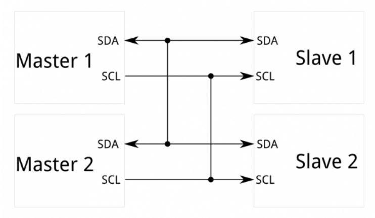
I'll be using I2C serial communication for communicating with my boards.Like the name suggests it uses only two pins,i.e: SDA- Serial Data and SCL- Serial clock.I2C is quite popular for its ease of use and large connectivity.They usually communicate as master and slave Where we can connect almost 128 (112) devices using 7 bit addressing and up to 1024 (1008) devices when using 10 bits addressing.
My plan was to design two boards which I'll be using for my final project which will act as slaves and to use the Hello echo world board that I made in the Electronic design week as the master.
Designing the board
My idea was to design two boards that I'll be using for my final project. One will be a servo driver and other will be an LED array.
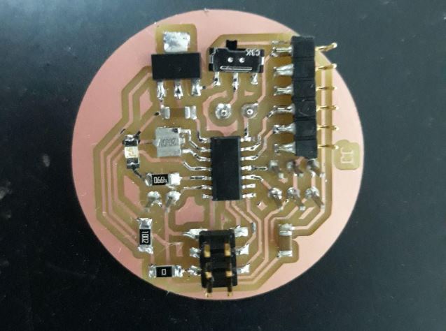
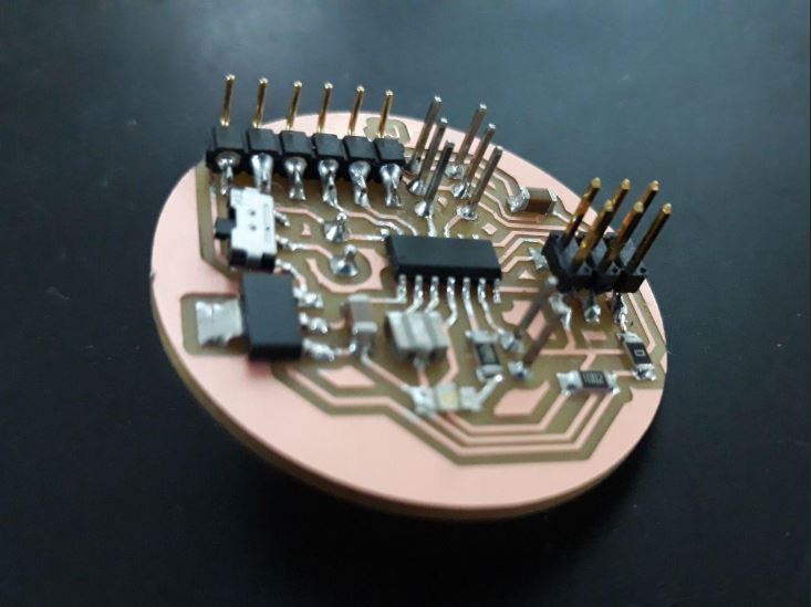
Servo Driver
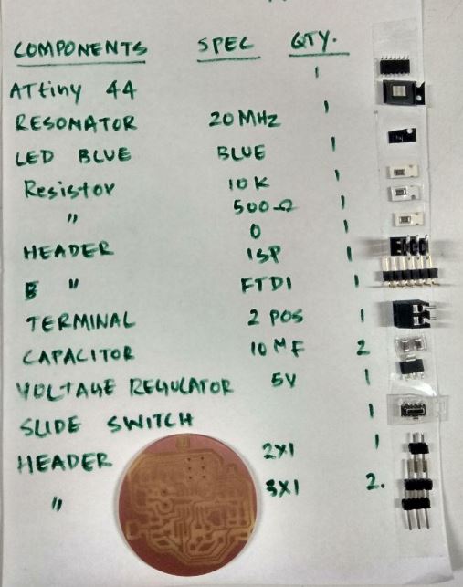
I used Attiny 44 in this board So I'll have to use the software servo to control the servos.I also added 20 Mhz resonator,A voltage regulator to provide external supply ,LEd and SLide switch.
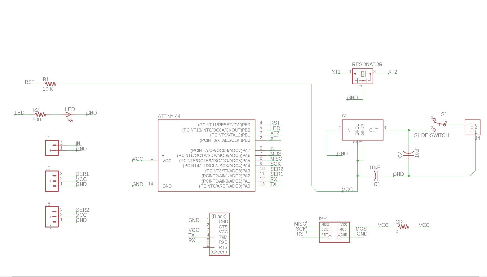

Download the design files here.
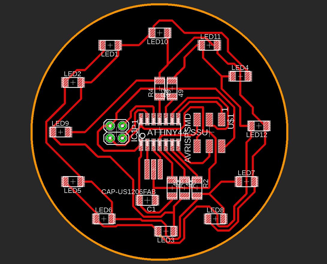
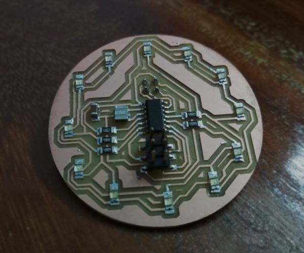
LED Array
Next I wanted to make a circular LED array taht I'll be using for my final project. I'll making an array of 12 LED and for controlling them I'll be using a Attiny44 MC.I'll have to use a method called Charlie Plexing since I dont have required LED pins in the ATtiny 44
Charlieplexing is a technique for driving a multiplexed display in which relatively few I/O pins on a microcontroller are used e.g. to drive an array of LEDs. The method uses the tri-state logic capabilities of microcontrollers in order to gain efficiency over traditional multiplexing(wiki).
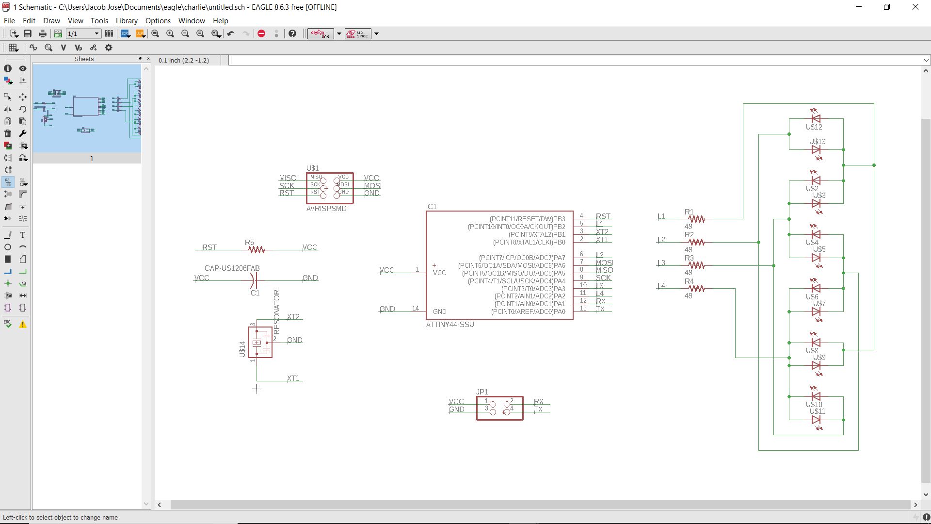
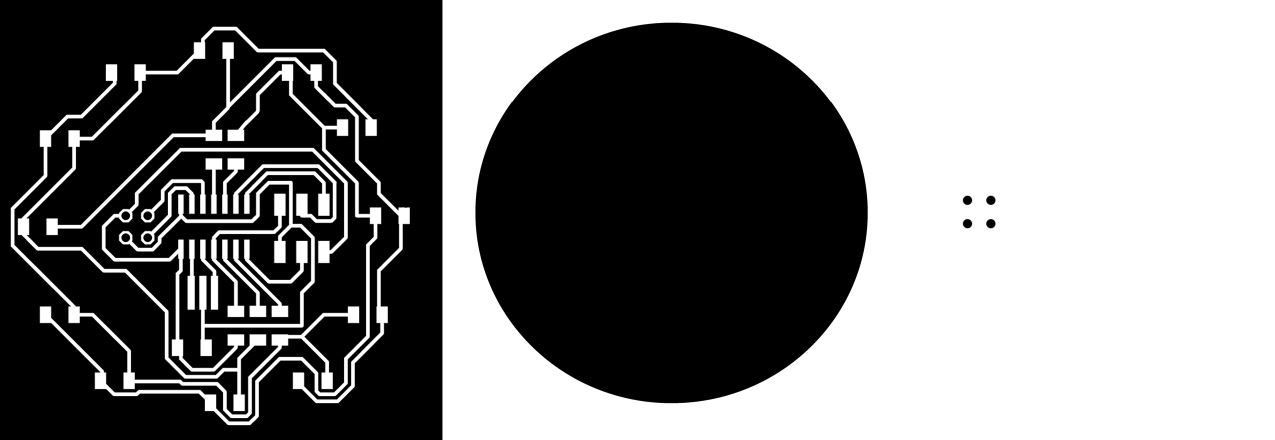
Download the design files here.
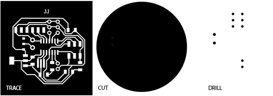
Fabricating the Boards
Servo Driver
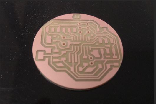
LED Array
Programming
First I started by running a test program in my LED array board. I wrote a simple code in Arduino IDE for running LED using charlie plexing library.The code is as follows.
		#include

			#define NUMBER_OF_PINS 4

			byte pins[] = {8,7,3,2};
			Charlieplex charlieplex = Charlieplex(pins , NUMBER_OF_PINS);

			charliePin led1 = { 0 , 1 };
			charliePin led2 = { 1 , 0 };
			charliePin led3 = { 0 , 2 };
			charliePin led4 = { 2 , 0 };
			charliePin led5 = { 1 , 2 };
			charliePin led6 = { 2 , 1 };
			charliePin led7 = { 1 , 3 };
			charliePin led8 = { 3 , 1 };
			charliePin led9 = { 0 , 3 };
			charliePin led10 = { 3 , 0 };
			charliePin led11 = { 2 , 3 };
			charliePin led12 = { 3 , 2 };
			void setup(){
						}
			void loop(){
					charlieplex.charlieWrite(led10,HIGH);
					delay(100);
					charlieplex.clear();
					charlieplex.charlieWrite(led11,HIGH);
					delay(100);
					charlieplex.clear();
					charlieplex.charlieWrite(led4,HIGH);
					delay(100);
					charlieplex.clear();
					charlieplex.charlieWrite(led12,HIGH);
					delay(100);
					charlieplex.clear();
					charlieplex.charlieWrite(led7,HIGH);
					delay(100);
					charlieplex.clear();
					charlieplex.charlieWrite(led8,HIGH);
					delay(100);
					charlieplex.clear();
					charlieplex.charlieWrite(led3,HIGH);
					delay(100);
					charlieplex.clear();
					charlieplex.charlieWrite(led6,HIGH);
					delay(100);
					charlieplex.clear();
					charlieplex.charlieWrite(led5,HIGH);
					delay(100);
					charlieplex.clear();
					charlieplex.charlieWrite(led9,HIGH);
					delay(100);
					charlieplex.clear();
					charlieplex.charlieWrite(led2,HIGH);
					delay(100);
					charlieplex.clear();
					charlieplex.charlieWrite(led1,HIGH);
					delay(100);
					charlieplex.clear();
			}
You can clearly see that the running LED is not functioning properly. You can see a small fluctuaion after the 9th LED .I didn't have time to trobleshoot it as I was already behind in the networking week and I had to complete the communication between the boards. Confirming my Boards are working I went on with the networking week.
I2C Communication
I first thought to test the I2C communication between two Boards i.e,1. Hello Echo world Board 2.LED Array in which the hello echo world board will act as a master and the LED array will be a slave. When the push button in Hello echo is pressed the LED array will be lit.
But after the initial tests my hello echo borad stopped working and I had to borrow Salmans hello Echo board.
Programming the boards
My idea was to use the LED array as slave and to execute a single round of running LED when the push button is pressed in the master board.Before progrmming I first had to change some settings in my Arduino IDE. Salman helped me in setting up my Arduino Ide.I first added a board manager called AttinyCore you can download it from here.
I also added the wire.h library which is the official arduino library for I2C communication.
	#include
		#include

		#define button A2

		void setup() {
			Wire.begin();

			pinMode(button, INPUT);

		}

		void loop() {
			int data;
			data = digitalRead(button);
			if (data == 1)
			{
			Wire.beginTransmission(8);
			Wire.write(1);
			Wire.endTransmission();
			}
			else {
			Wire.beginTransmission(8);
			Wire.write(0);
			Wire.endTransmission();
			}

		}
		}
My idea was to execute a single round of running LED when the button is pressed in the master. But the code didnt work and I had to settle for a much simpler code where anyone of the LED will be kept ON when the button is pressed.The code is as follows.
#include
	#include
	#define NUMBER_OF_PINS 4
	byte pins[] = {8, 7, 3, 2};
	Charlieplex charlieplex = Charlieplex(pins , NUMBER_OF_PINS);
	charliePin led10 = { 3 , 0 };

	void setup()
		{
		Wire.begin(8);                // join i2c bus with address #8
		Wire.onReceive(receiveEvent); // register event
		}


		void loop() {
					}


		void receiveEvent(int howMany)
		{
			int x = Wire.read();    // receive byte as an integer
			if (x == 1)
			{
			charlieplex.charlieWrite(led10, HIGH);
			}
			if (x == 0)
			{
			charlieplex.charlieWrite(led10, LOW);
			charlieplex.clear();
			}
		}
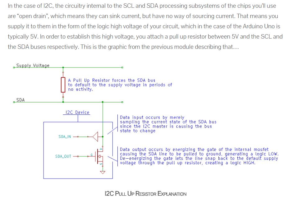
After programming my board I couldn't get my boards communicate with each other. After troubleshooting for some time I found that it was a problem with design of my board. By refering the Attiny44 datasheet page no 122 there is a simplified diagram given for the Two wire mode operation in which they have speacified to add a Pull up resistor between master and salve (SCK and SDA).
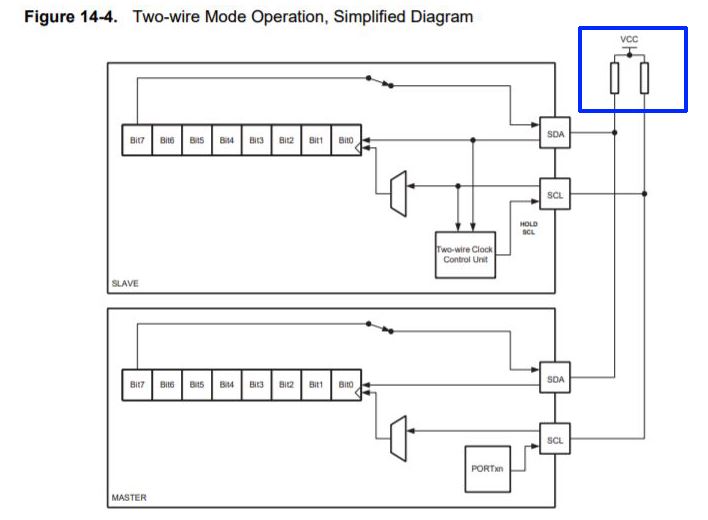
The explanation for it is given below.
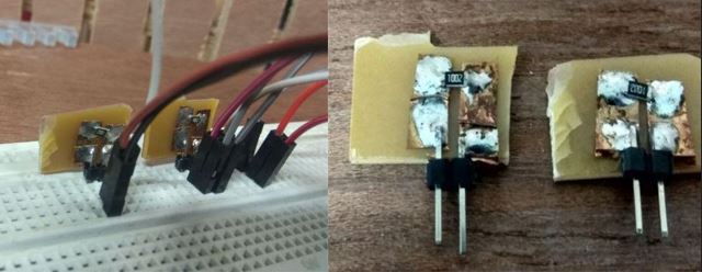
With no time to mill another board I thought to improvise and use a bread board to add the 10K resistor between SCK and SDA.Salman for the rescue again as he had already made one for his assignment and I borrowed it :).
3 Board communication
Having done with the communication btw two boards now I have to try to communicate with the 3 boards that I've made. I have to communicate with my LED array board and Motor driver board simultaneously this time addressing each one of them using I2C communication.
Programming
The code for one master and two slaves were written in Arduino IDE.
	#include
	#include
	#define Rx 0
	#define Tx 1
	SoftwareSerial myserial(Rx, Tx);

	void setup() {
		Wire.begin();
		myserial.begin(9600);
	}

	void loop() {
		char d;
		if (myserial.available() > 0)
		{
		d = myserial.read();
		if (d == '1')
		{
			Wire.beginTransmission(1);
			Wire.write(1);
			Wire.endTransmission();
			myserial.println("send :- ");
			myserial.print(d);

		}
		if (d == '2') {
			Wire.beginTransmission(2);
			Wire.write(2);
			Wire.endTransmission();
			myserial.println("send :- ");
			myserial.print(d);

		}
		if (d == '3') {
			Wire.beginTransmission(2);
			Wire.write(3);
			Wire.endTransmission();
			myserial.println("send :- ");
			myserial.print(d);

		}
		if (d == '4') {
			Wire.beginTransmission(1);
			Wire.write(4);
			Wire.endTransmission();
			myserial.println("send :- ");
			myserial.print(d);

		}

		}
	}
Since my hello echo world board is not working I will be using the Phototransistor board from the Input week as the Master.
	#include
	#include

	#define NUMBER_OF_PINS 4


	byte pins[] = {8, 7, 3, 2};
	Charlieplex charlieplex = Charlieplex(pins , NUMBER_OF_PINS);


	charliePin led10 = { 3 , 0 };

	void setup()
				{
					Wire.begin(2);                // join i2c bus with address #8
					Wire.onReceive(receiveEvent); // register event

				}

	void loop()
				{

				}


	void receiveEvent(int howMany) {

			int x = Wire.read();    // receive byte as an integer

			if (x == 2)
				{
					charlieplex.charlieWrite(led10, HIGH);

				}
			if (x == 3)
				{
				charlieplex.charlieWrite(led10, LOW);
				charlieplex.clear();

				}
									}
			#include


				void setup() {
				Wire.begin(1);
				Wire.onReceive(receiveEvent);

				pinMode(8,OUTPUT);

				}

				void loop() {
				delay(100);
				}


				void receiveEvent(int howMany) {
				int x = Wire.read();
				if (x == 1)
				{
					digitalWrite(8,HIGH);

				}
				if(x == 4)
				{
					digitalWrite(8,LOW);

				}

				}
Problems and Troubleshooting
I connected the Boards using I2C and the breadboard with the resistor. On sending the serial data I didn't see the LED's blinking. So I tried reconnecting the wires checked again but the results were same. I then disconnected the slave 2 and send the serial data once more this time the slave 1 was working. I then disconnected slave 1 and connected slave2 and checked again and slave 2 was working then. So I couldn't communicate with two boards simultaneously. I thought there could be some problem with the addressing in the I2C communication started reprogramming my boards. But after uploading the codes twice my slave 1 just stopped working and then I had to check whats wrong with that board :(. I tried resoldering the ISP headers thinking it could be some problem caused by the cold soldering. After hours of frustrating debugging, I tried changing the Attiny 44 MC. This fixed the issue and I could burn the bootloader. But after uploading the program a few times I lost the board again. It was getting really frustruating as I have already moved to the next week and I've got pending works now. So I stopped the work there and went to the next week and I'll be fixing this up later.
