
Week Four
Assignment
What I did
Introduction
This week is really exciting because this is the first week we are introduced to machines. So we are starting to make that something that we are planning for our final project. This week Neil gave us an introduction to all the vinyl and laser cutters. He also gave us an idea about all the cool stuff we can make with this machines. I really liked the concept of making mini machines and origamis using laser cut copper sheets. This weeks assignment is to vinyl cut something and to laser cut any press-fit components which can be fixed in different ways.
Vinyl Cutter
Machine details and operation
Our instructor gave us a introduction how to operate the machine. You can read the users manual here.
As my first work, I am planning to vinyl cut a laptop skin for my Dell laptop. SO I am planning to convert an image into vector format in Illustrator so that I can use the Dell logo in some creative way.
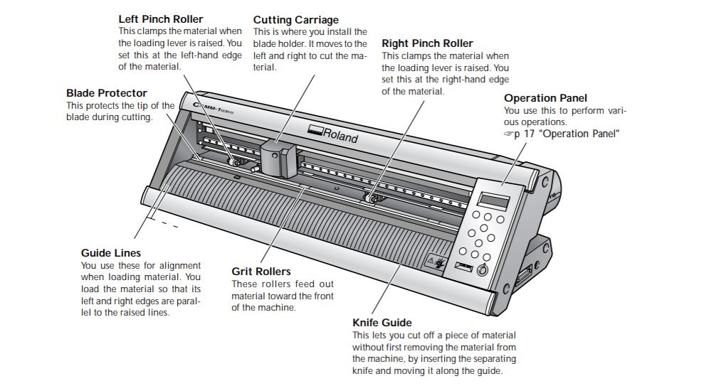
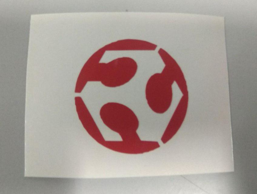
But first I needed to test cut something. I thought of cutting a fab lab logo. I've already traced a fab lab logo using illustrator in the previous week's assignment so I planned to cut this design on vinyl cutter and to place it on my phone. I exported the file to PNG format and it was ready for cutting. Our instructor gave us an introduction to the Roland vinyl cutter and information on how to set up the machine like setting the origin, changing the material types to roller or pieces, he even demonstrated a test cut to show us the procedures involved.
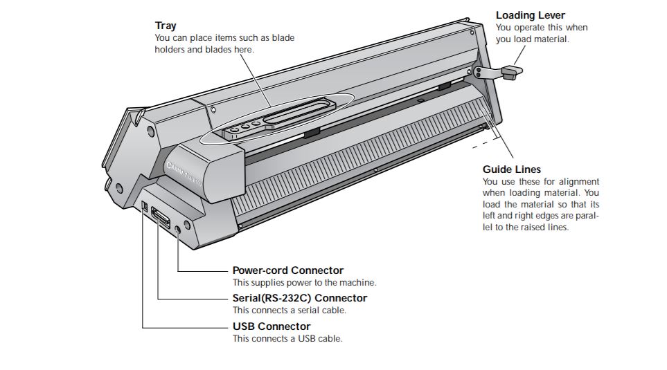
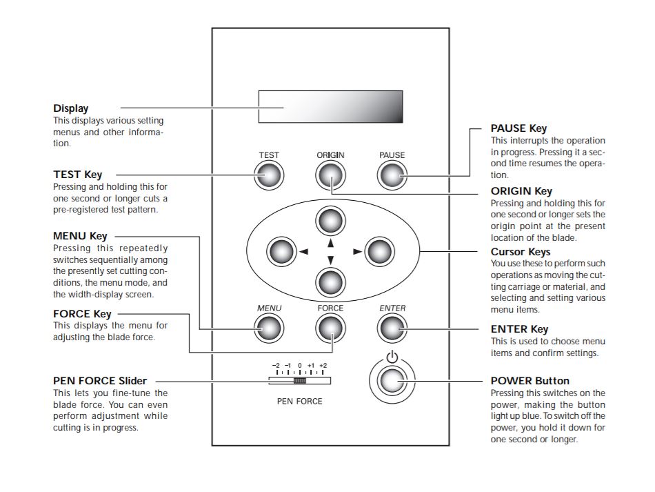
For setting up the vinyl first pull the Loading lever and place the vinyl sheets on to the Grit rollers.Once the vinyl is in place pull forward the Loading lever again to secure the vinyl sheets in postion.Now using the cursor keys in operations panel adjust the position of cutting carriage.Once in the right postion select the piece or roll option and press the enter key. To set the origin press on the origin key for a few seconds.
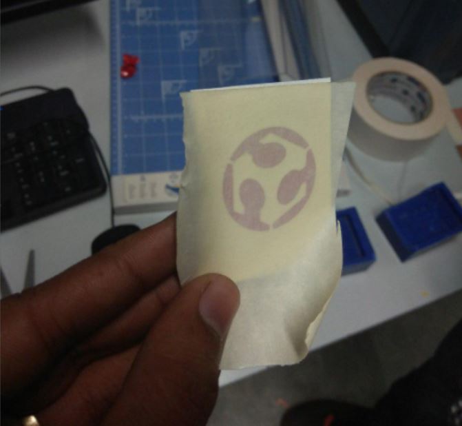
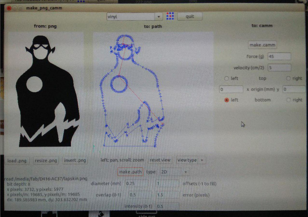
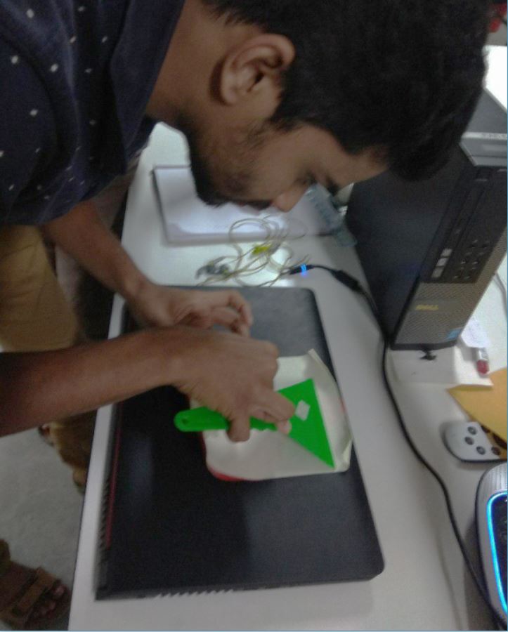
We used the Fab module in ubuntu to set up the file and to adjust the cutting force and speed.Our instructor also showed us how to transfer the pieces of vinyl to the required surface using a masking tape. My very first cut didn't go well. Since my logo was pretty small I thought to cut it on a small leftover piece but I forgot to adjust the rollers to the edges of the vinyl piece.So, once the cutting started the vinyl slipped and all I got was some scratches on the vinyl. On the Second go, I fixed the rollers and I also reduced the cutting speed and this was the results.
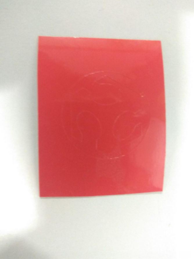
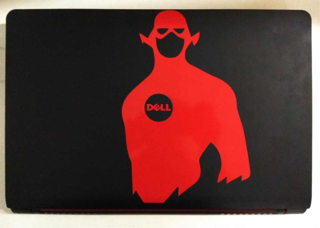
After the test print, I went for the laptop skin. The idea was to go for some superhero theme and to replace the symbol on their chest with my dell logo. I searched for some pictures and I really liked the picture of 'flash' which had a really nice rounded emblem on its chest. So I took the image to Illustrator and adjusted the dimensions in order to fit my dell logo. I then exported the file to png format and started cutting. I went for a red colored vinyl because my laptop already had a RED & BLACK theme on it. But on the first cut, I realized that I've made a mistake while editing in Illustrator. The image itself was quite big considering the laptop size and I further scaled it up to adjust to the dell logo which further increased its size and its length was higher than the width of the vinyl rolls. So, only half of the image was cut on the vinyl.
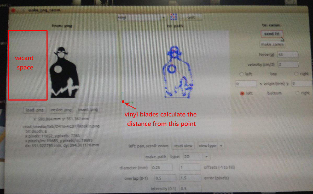
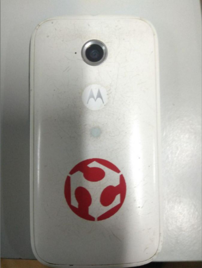
Fixing this was quite easy as there were many vacant spaces on either side of the image.All I had to do was to crop the image and cut it again. It was all done in a few minutes. This is how my laptop looks now :)

Download this image file here.
Laser Cutting
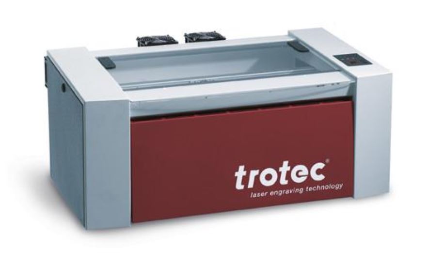
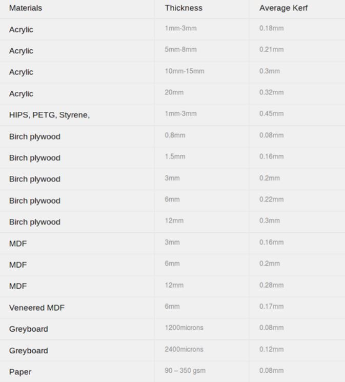
The next machine we have to master this week was a laser cutter. We have a Trotec Speedy 100 CO2 laser cutter and engraver, at Fablab Kochi, which is capable of cutting and engraving on a wide range of materials. We have acrylic of various thickness, plywoods, and cardboards for doing assignments. This weeks assignment is to create a parametric press fit design which can be arranged in various forms.
Machine details
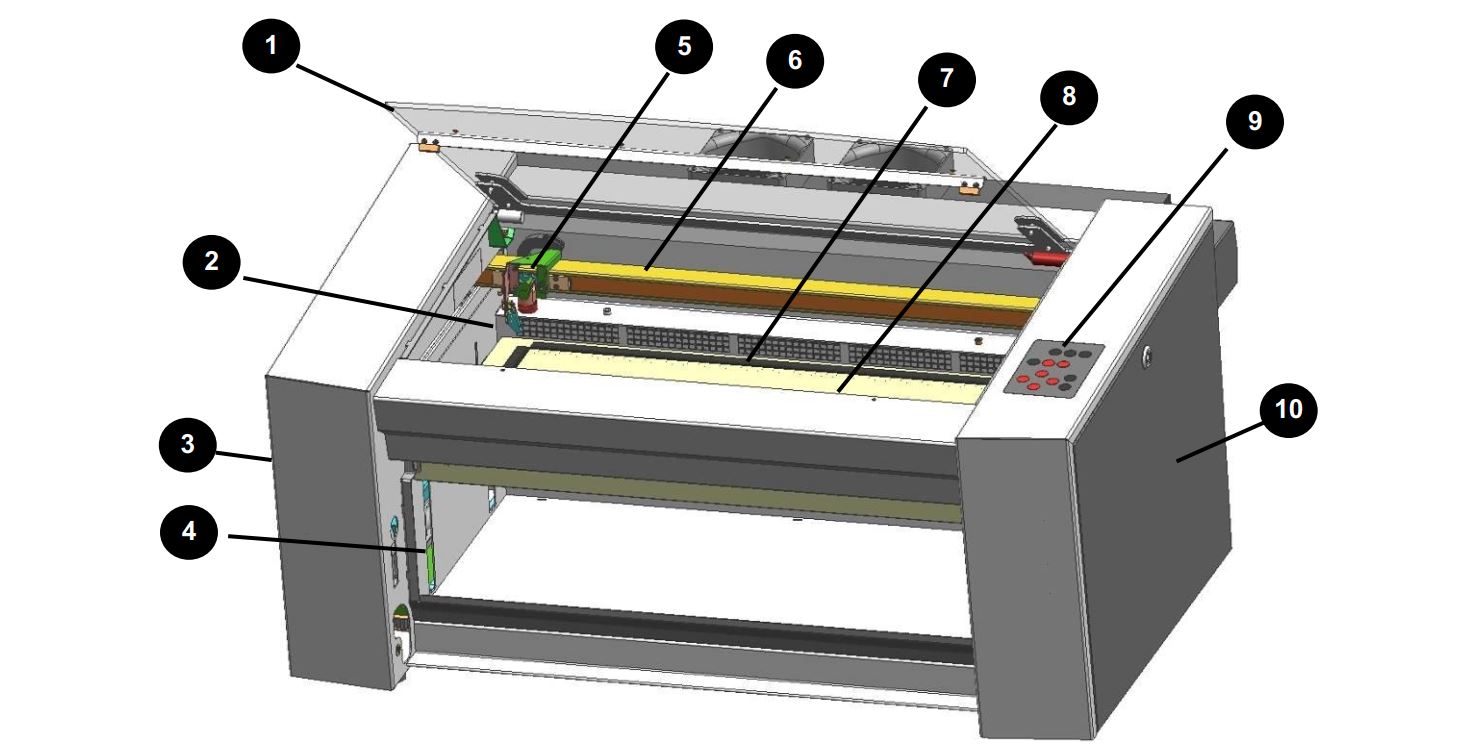
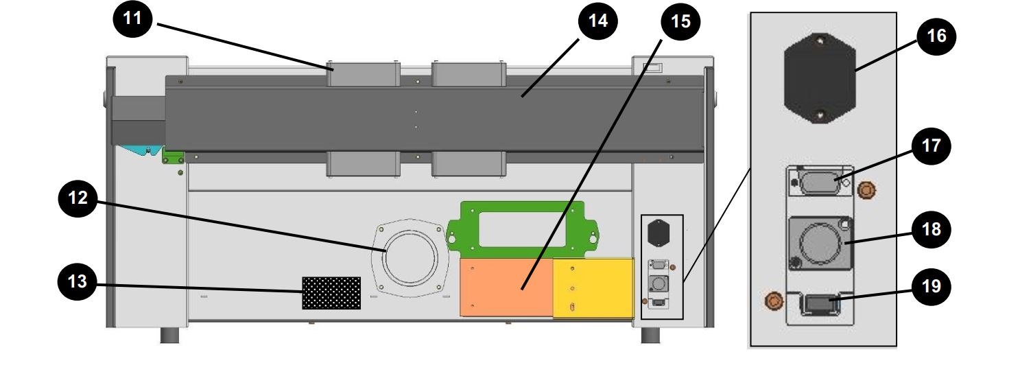
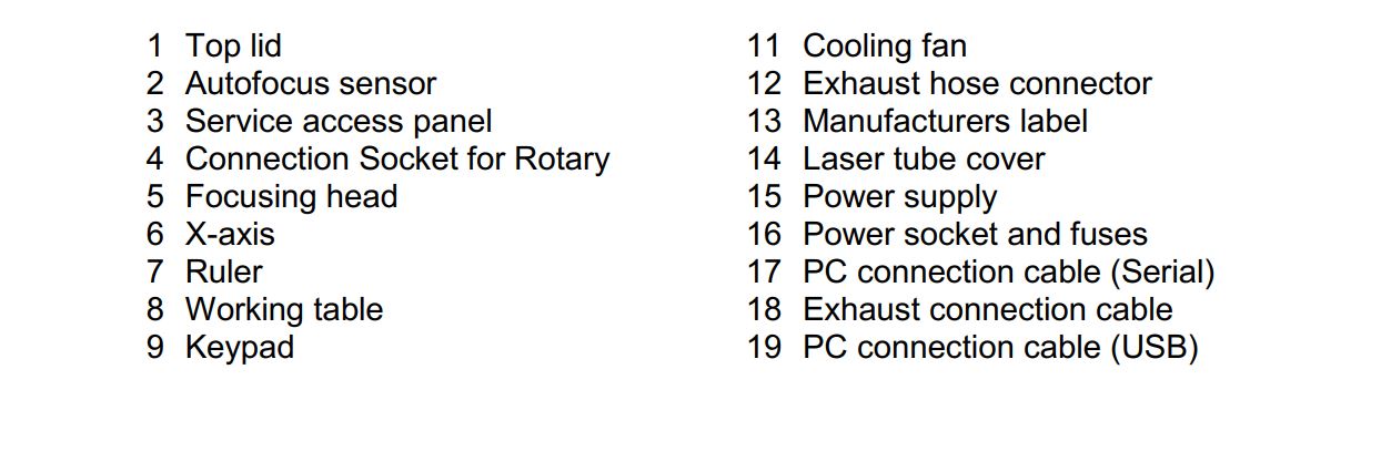
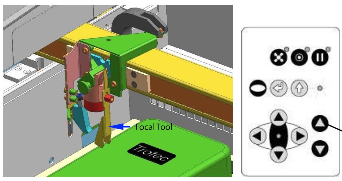
Move the processing head over the material to be engraved by means of the positioning keys X/Y.Hang the focus tool on the external ring of the working head so that the focus tool can move unhindered. Move the working table upwards by pressing the Z positioning key (1). While doing this carefully observe the focus tool.Before the focus tool reaches the work piece, move the working table upwards only very slowly and step by step by briefly tapping the positioning key, until the tool tilts to the side. Now the lens is focused onto the surface of the material (Source: Users maual.)
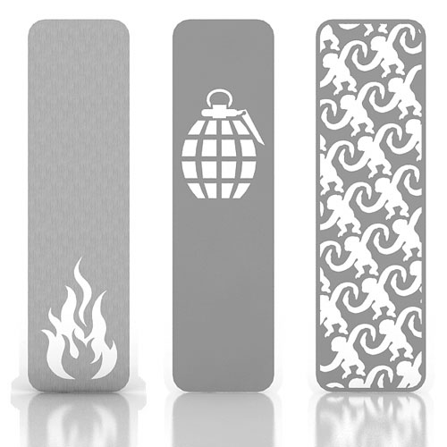
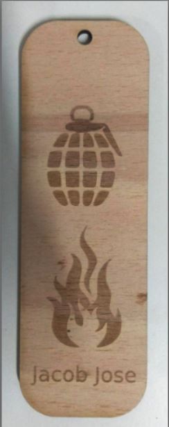
Before going to the press fit design I wanted to test the machine with something simpler to study various power and velocity values for cutting and engraving.I had this idea of making a bookmark for a really long time. I thought it would be great to make a bookmark out of a 3mm plywood sheet using the laser cutter.
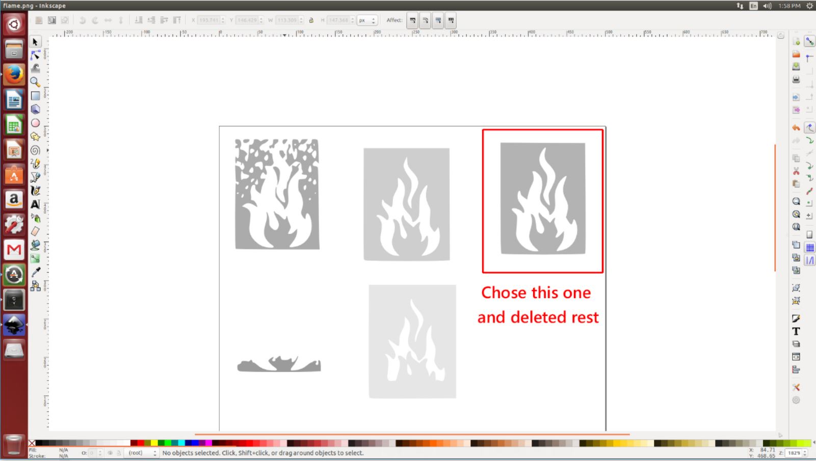
I wanted to try Gimp and Inkscape. So, I thought to design my bookmark using these applications. I used gimp for basic editing and cropping of the image. And after that, I used Inkscape for tracing and setting the layout of the bookmark. I really liked Inkscape because it had some really cool tracing options compared to illustrator and it was open source.


In Inkscape, while tracing you can set the no of scans and select the layer which suites you best. This can be easily converted to a vector monochrome image. I converted both these images to vector using this method.
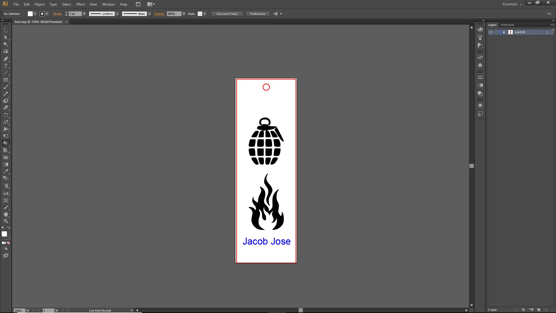
I used 3 colors Red, Black, and Blue for my design. In our laser cutter, we can assign different colors for different powers and velocities.In our machine, we set the red color to cut, blue and black colors to engrave.
Before cutting we have to first set the focus of the laser. For this, a small component is placed on the laser generator and the laser bed is moved up till this component falls. This is the focusing point of the laser. Now, we have to set the origin using the arrow keys in the machine.
One can directly cut from Inkscape by pressing ctrl+P and adjusting the print settings.This will take us to the Trotec software where we can further select different materials, different power, and velocity options and can assign specific colors for specific type of cut and engraving
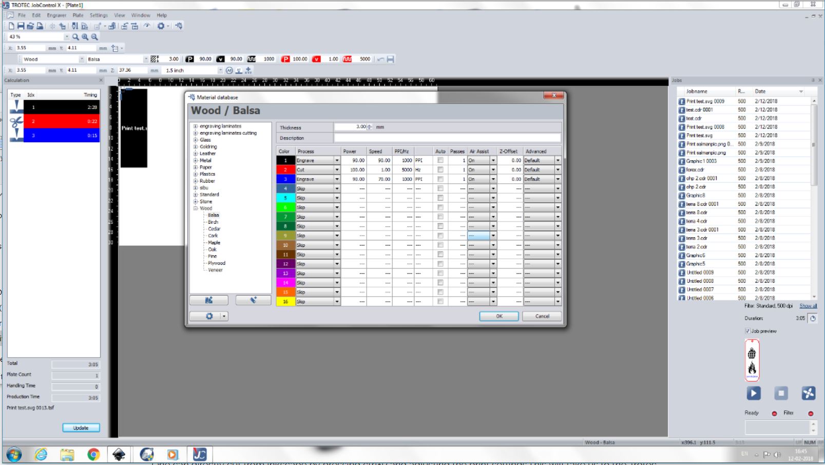
My initial attempts failed because the machine was not recognizing the blue color. We tried changing colors and assigning different values for each color but still, it didn't recognize colors other than red and black. After many attempts, this issue was resolved. It was a small problem with the settings. Someone accidentally switched off the color recognition. I selected a balsa 3mm thickness plywood for making my bookmark. And this is how it ended up finally.
Press Fit Designs
The main assignment for this week was to create a parametric press fit design. Niel specifically asked us to make it parametric because in parametric design each measurement is related to other values with some kind of equations. So that when we tweak one the rest changes automatically. Parametric designing is a really good design principle to follow because it makes our project easily editable. In case of our press fit design, we can always use different materials ranging from cardboard pieces to acrylic and each of them has different thickness and kerf values. So redesigning every value for different materials is a tedious task. But in parametric design, all you have to do is to change the thickness value according to your materials and rest of the values automatically adjusts to this.
There are many parametric software available like AutoCAD, SolidWorks etc. Since I am a little bit experienced in SolidWorks I choose it for my designing. My idea was to first draw a 2d drawing extrude them and see how they fit together in an assembly.
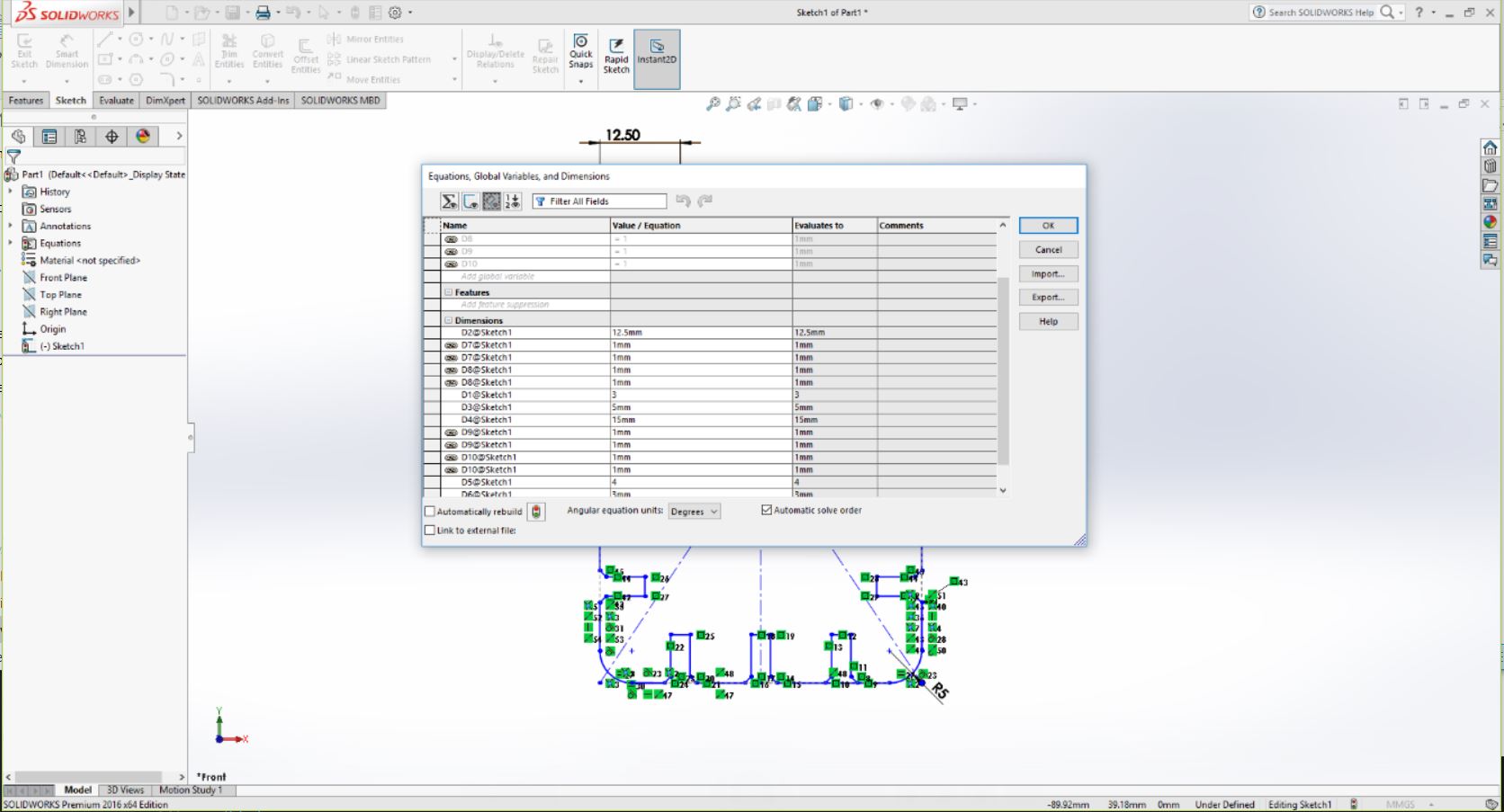
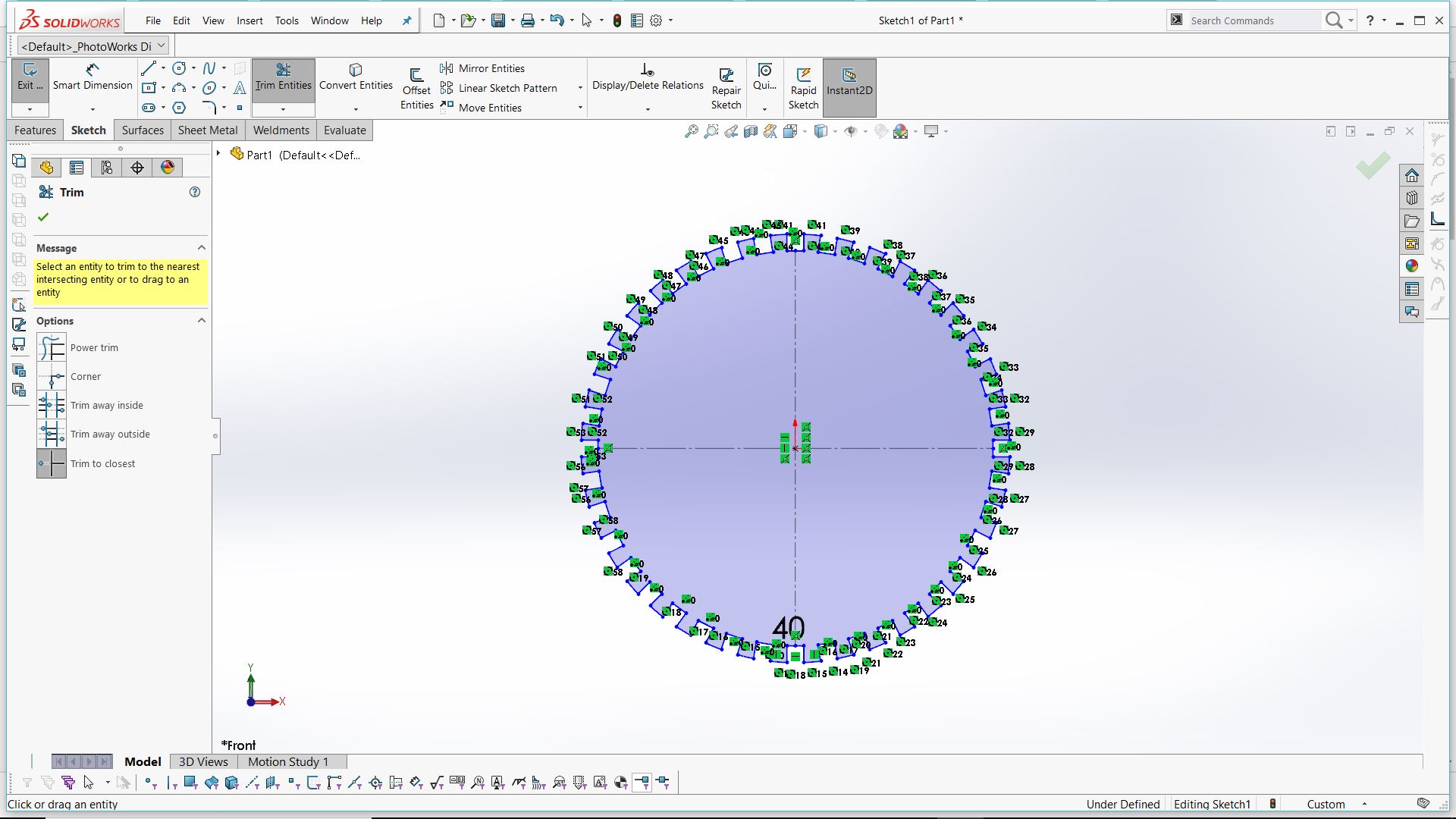
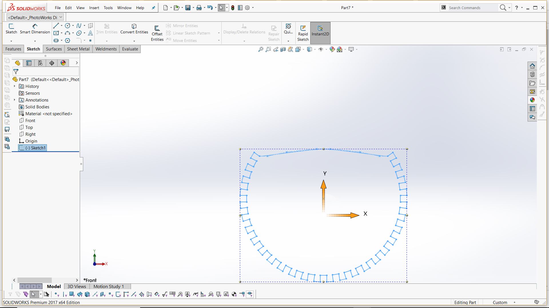
I wanted to design two simple parts which can be arranged to form different shapes. I started 2 d designing in solid works and making it parametric was pretty easy.One method is by going to Tools - Equations and setting specific equation connecting different measurements. There is a much simpler method, specify each relation while designing. Use tools like smart dimension and other relationship tools. This way you can make the design parametric.
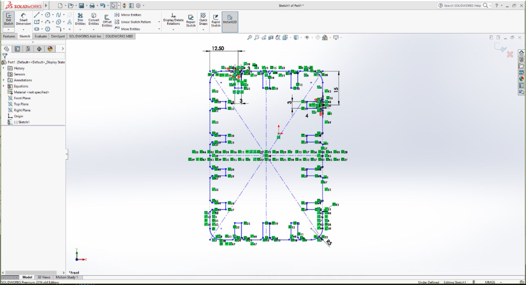
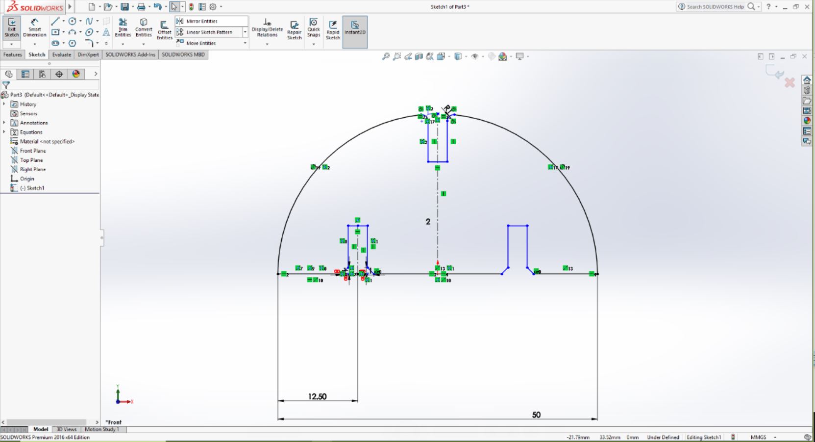
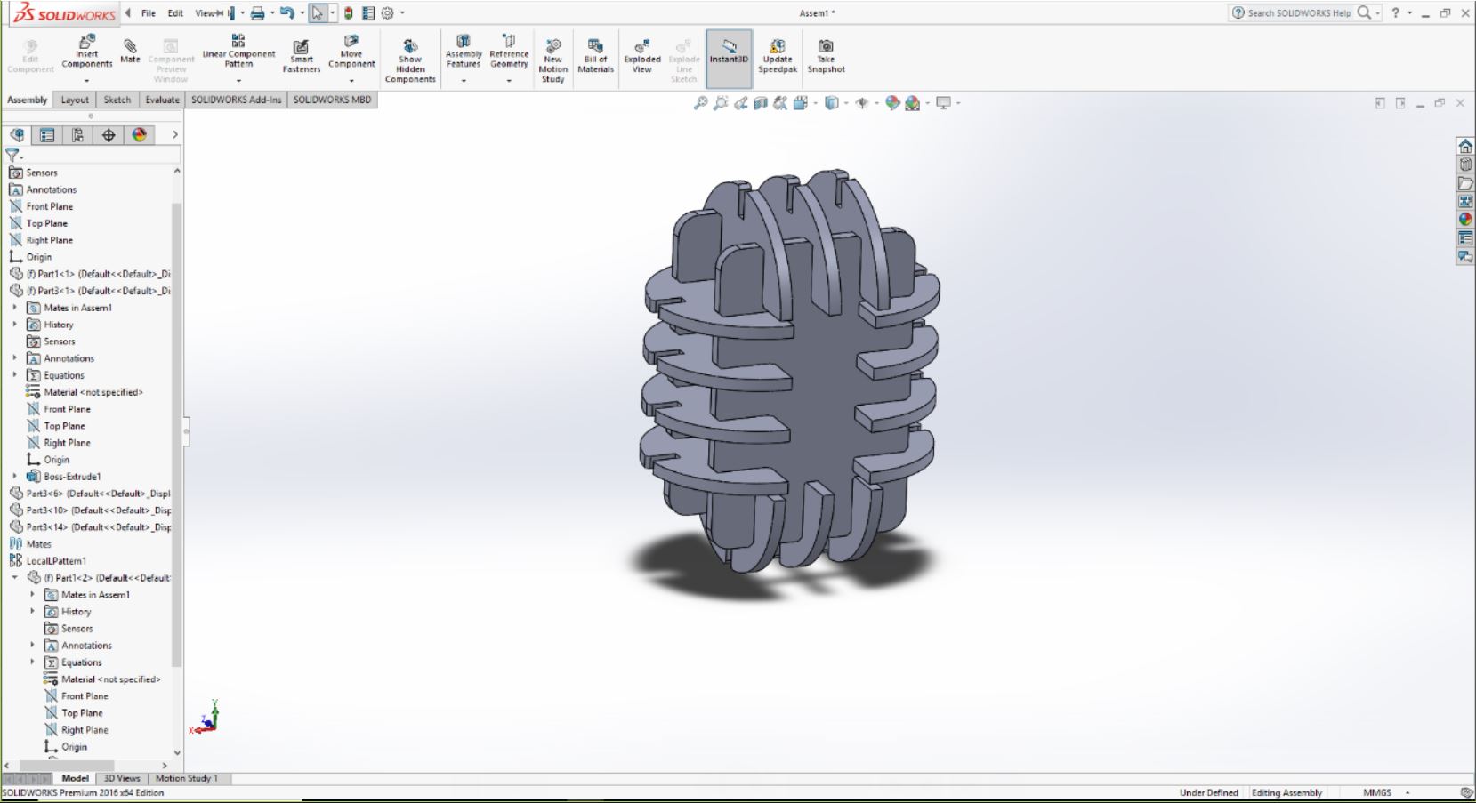
After this, I extruded these 2d designs to form two separate parts of thickness 3 mm. Later I opened an assembly file and assembled these two components to see how well they fit and to have a basic idea of arranging different spaces to insert different parts.On my first check, I noticed that there was a slight problem with the spacing of my part 1 file. Components from the top slots were colliding with the parts from the side slots.
In Solidworks, we can edit the separate part files from the assembly file itself by right-clicking on the parts and selecting edit parts option. I quickly edited the 2d files by this method and my design was ready :)
Another thing I have to consider while designing was the kerf value.Kerf is simply the amount of material removed by the cutting process. In our case, it is the diameter of our case beam. So while designing we have to put a slight offset to account for this kerf loss. Before cutting I measured the thickness of the cardboard piece using a vernier and it showed a value slightly above 4mm. So, I thought to put a 4mm width for the slots (considering the kerf loses) where the components mate.The width of the slots in my first design was 3mm (I thought the cardboard pieces were of 3mm thickness), But thanks to the parametric design all I had to do was to change this value to 4mm and all other values changed accordingly.
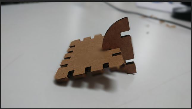
Next, it was time to test my design. I changed the sketch color to red(red is the color code for cutting) in Solidworks and exported the files in .dxf format.As the pc connected to the laser cutter doesn't have a Solidworks software I opened the file in Coral draw. But then the colors of the sketches were changed back to a black color. I changed it and pressed Ctrl+P which is the shortcut for printing. I made necessary changes in the print settings like arranging the window and positioning the files to reduce the material wastage.And after this, our file was supposed to be opened at the Trotec software.But, I got a message "No Work Found". We tried different methods but we got the same message. After many failed attempts I planned to check it with Rhino. I imported the .dxf file in Rhino and made necessary changes in the layer colors and template alignment. But this time the work was identified in the Trotec software. I focussed the laser, set the origin and quickly made a test cut. Is was a perfect fit :)
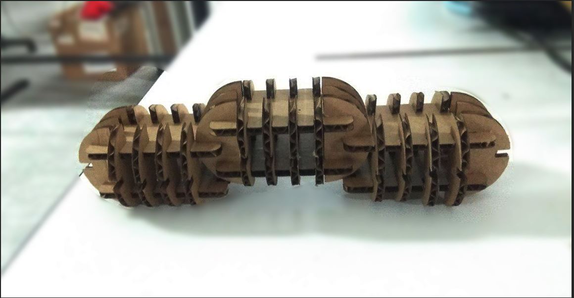
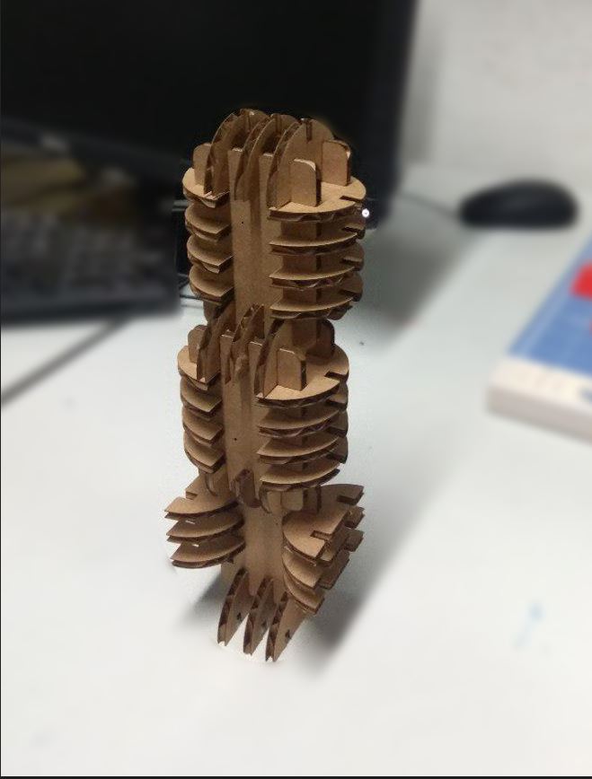
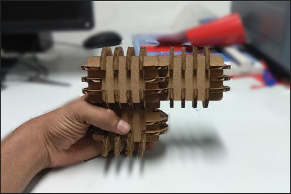
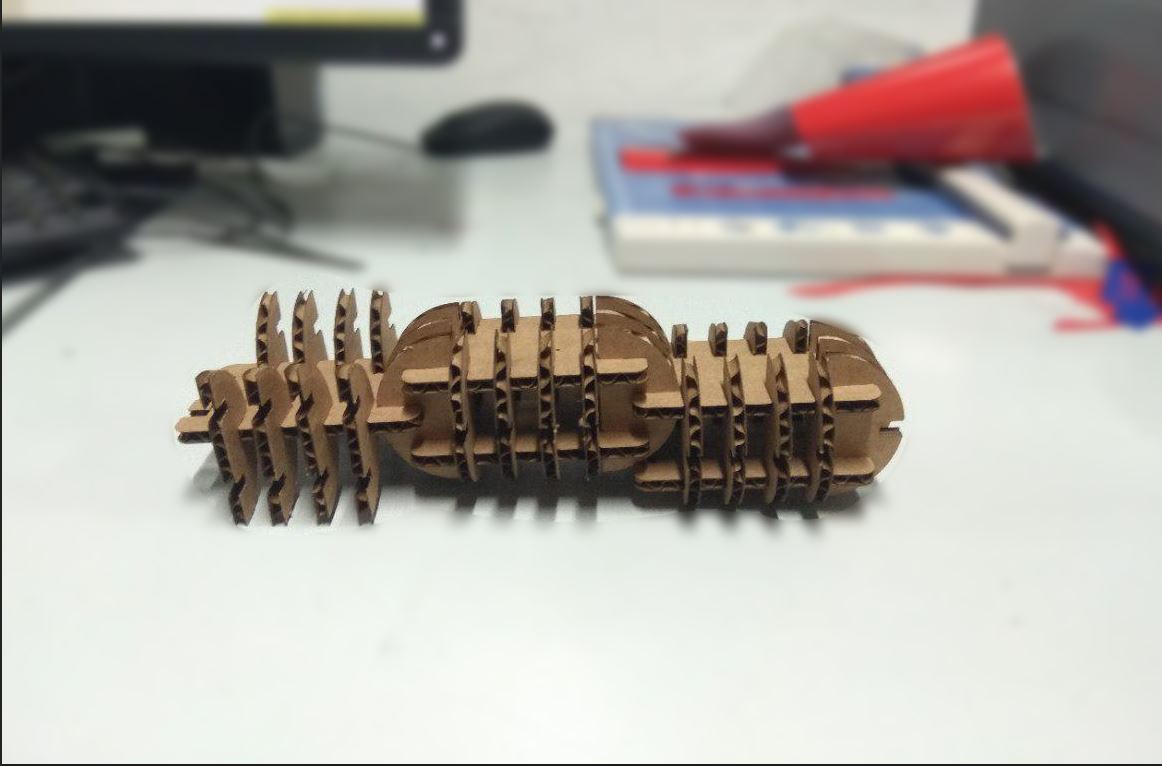
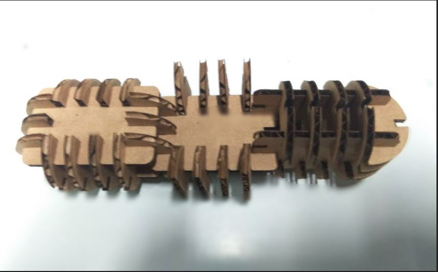
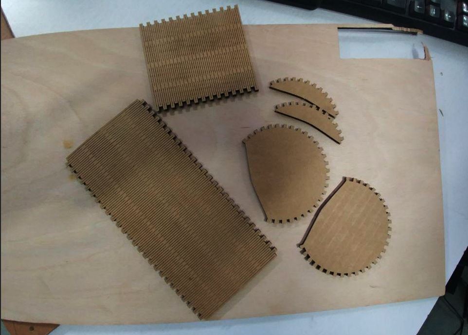
I completed with the rest of the cutting and started making different shapes.This was what I got :D
Design Files
Other expiriments
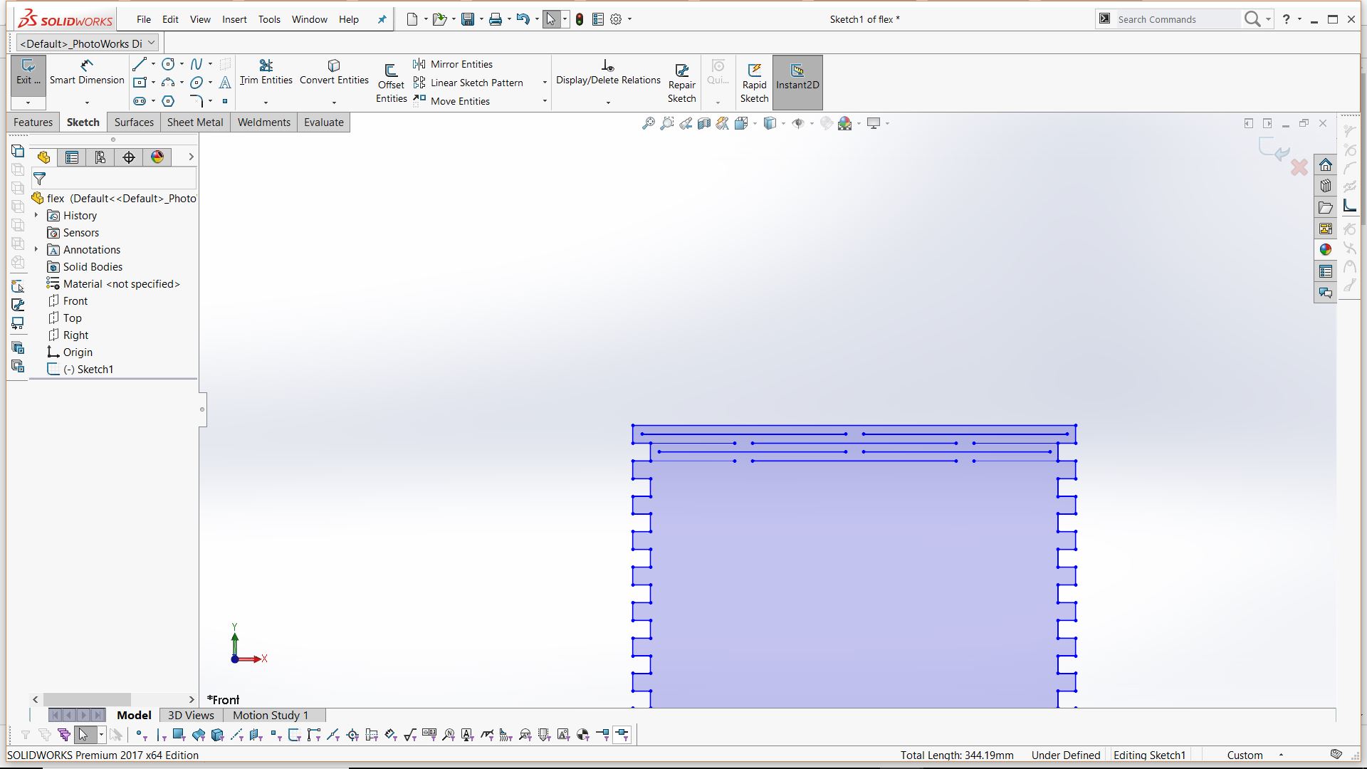
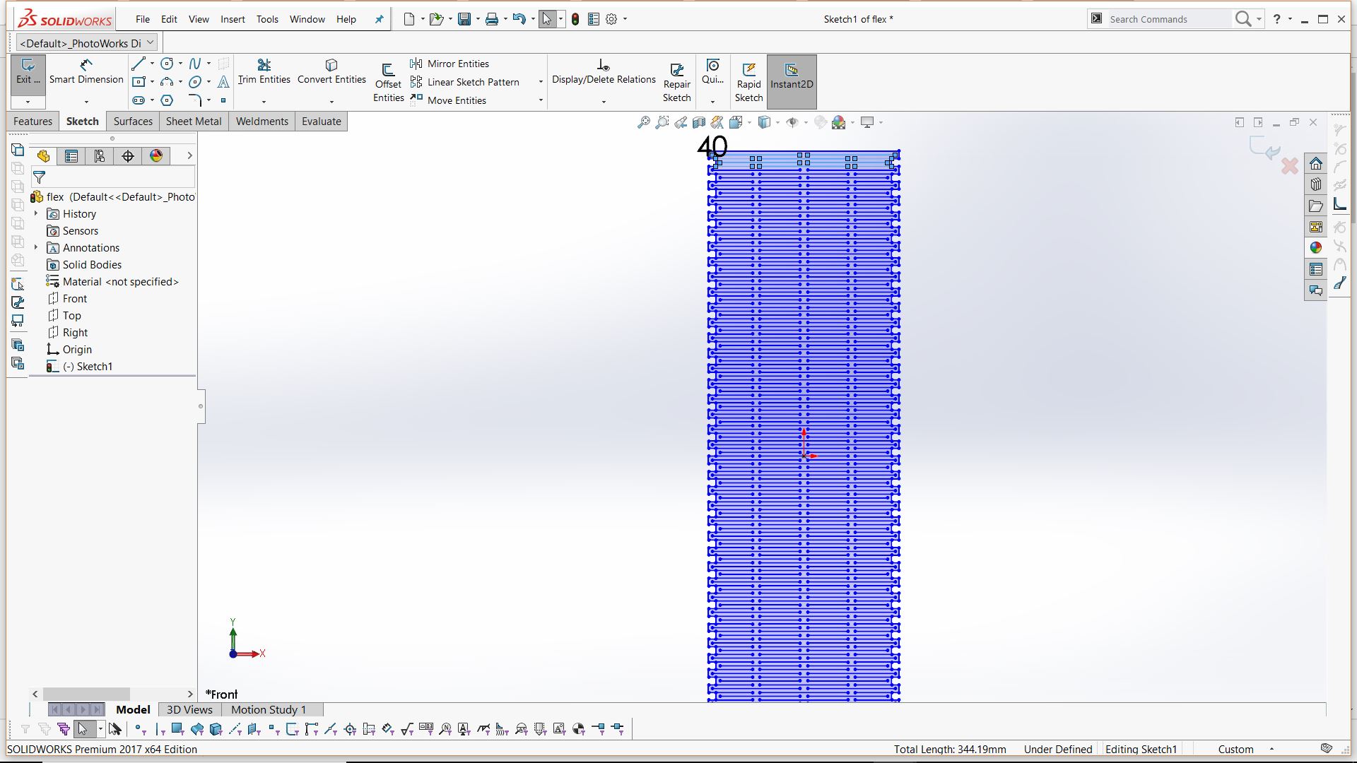
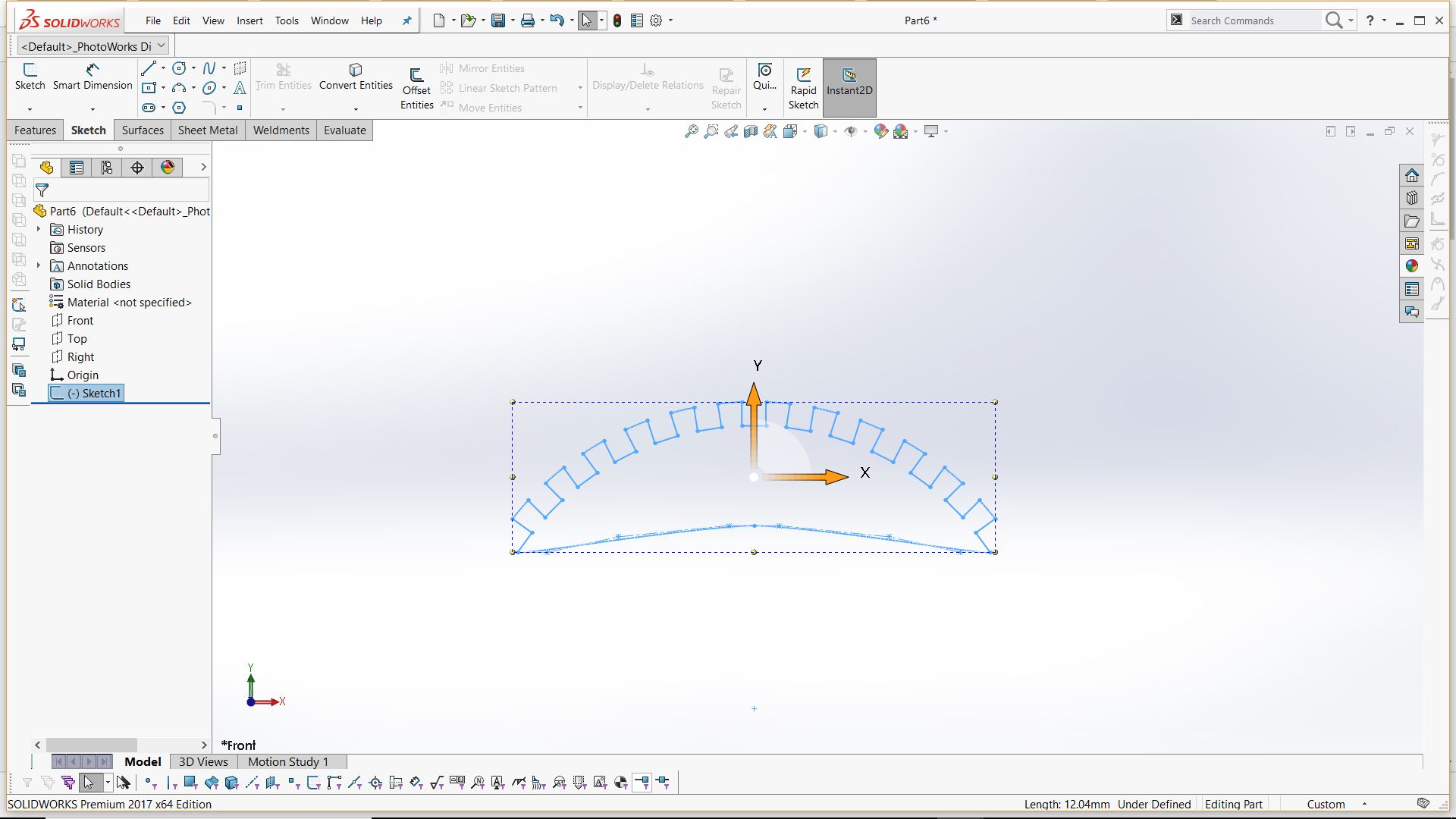
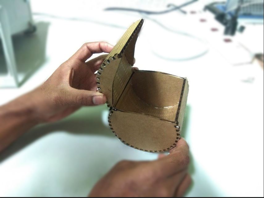
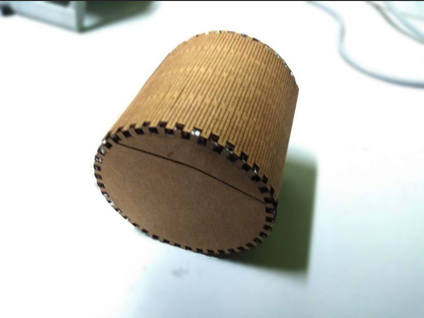
I am also trying to make some kind of box with flexures.
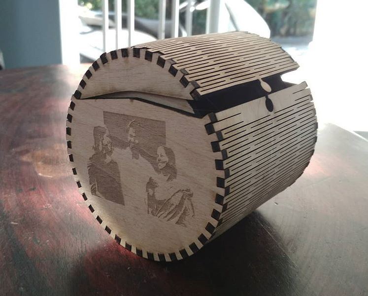
I also added a picture of my family using inkscape on the sides
Download the design files here.
Group Assignment
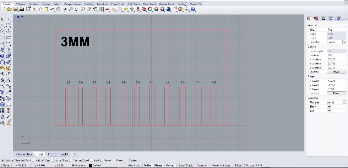
As a part of our group project we made a kerf scale. Kerf is simply the amount of materilal removed during the cutting process.The different kerf scales is as follows.
Dwonload the design file here.
Power - 75
Velocity - .90
Freq - 7000
Power - 75
Velocity - 90
Freq - 500
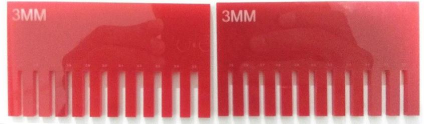
The kerf value obatined was about .20mm
