
Week Six
Assignment
What I did
Introduction
This week was really exciting because it was the 3D printing week. I myself as a designer wanted to try 3D printing for a really long time.
This week we studied different 3D printing and 3d scanning technologies and different machines involved in it. 3D printing is an additive manufacturing technology in which solid models are made by adding layers of material one after other. There are different methods for the same like FDM (Fused Deposit Machining), SLS (Selective Laser Sintering) etc. FDM is the most commonly used technology in which a small amount of material is fused and extruded through a nozzle to form thin layers of a cross-section. In SLS technology successive layers of powders are fused together using a laser.
In our lab, we have two FDM printers, an Ultimaker 2 and a Dimension SST 1200. This weeks assignment is to design something that cannot be made using a subtractive method and to 3d print it.Also, we have to 3d scan an object using any of the scanning methods. In our lab, we have mainly two machines for scanning purposes a Modella MDX 20 milling machine and a Kinect Xbox 360. Our group assignment was to test the design rules of our printer.
Group Assignment : Testing 3D printer
Our group assignment was to test the design rules of our printer. We used this design file from Thingiverse for the same.The following are the design specifications of this particular test file.
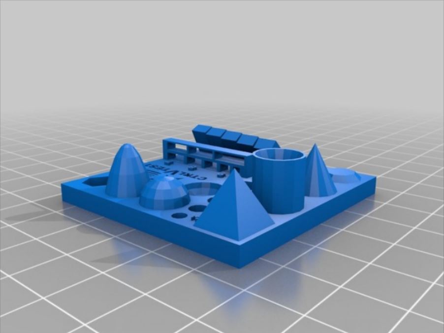
There is two process that we have to follow before printing. The first one is to export the file to STL format. The next one is to edit this file in a Slicer and to convert it to a GCODE. A slicer is a software in which the whole design is sliced into successive layers for the printer to understand. We can also provide support materials and edit the print settings like layer thickness, infill density etc which determines the quality of the print. We were planning to test the print on Ultimaker 2. So, we used Cura which is a slicer software for ultimaker.
Test 1
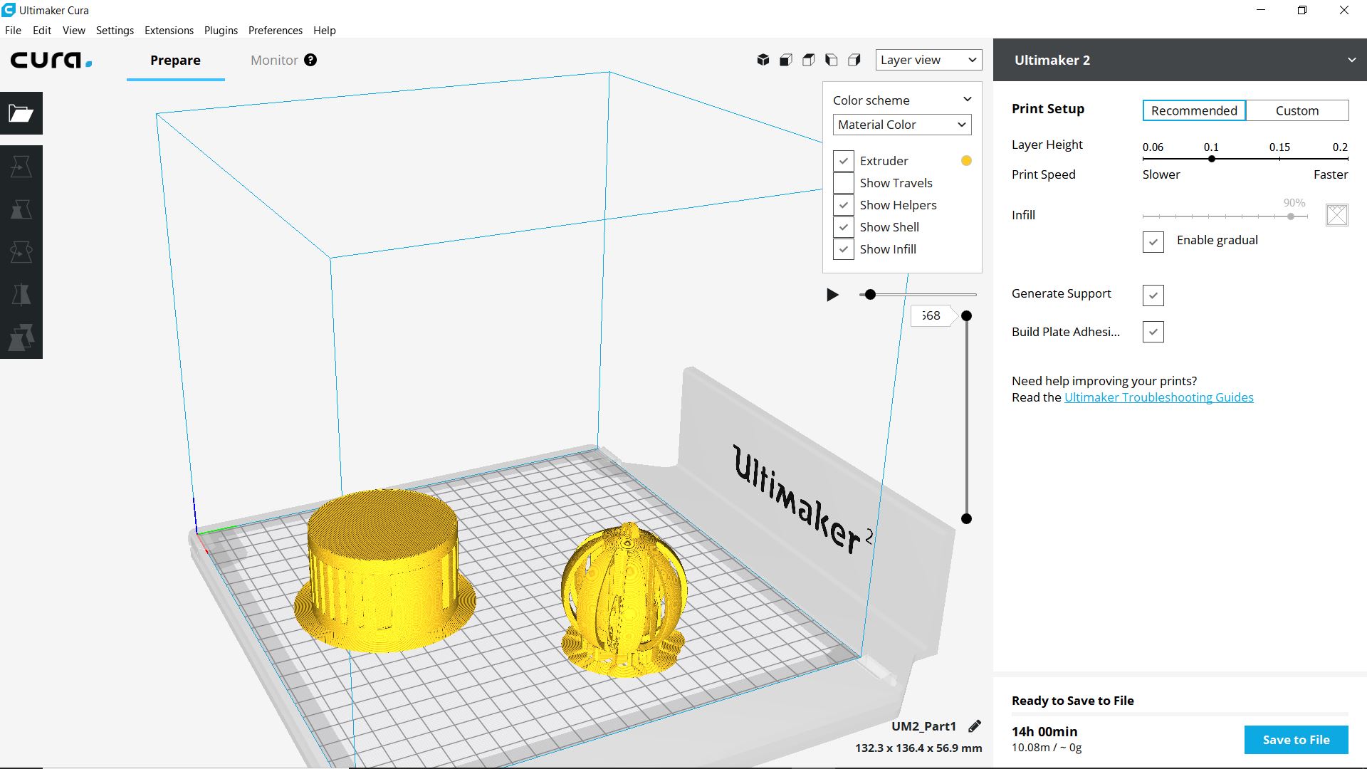
For the first print, we planned to go with a default and recommended settings keeping the layer height at .15 we also selected the option 'enable gradual' which automatically set the infill density to 80%. We also selected the plate adhesive option which will create a brim around the printed body which keeps the print in position. The total print time was shown as 1 hr 30 min.
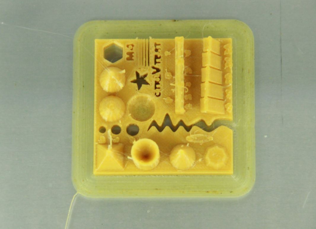
The first print came out quite good. The only problem that I felt was with the bridge print in which the top three members (7,8 and9mm) collapsed and the extra brim at the curving slot which was unnecessary. So the maximum bridge length that we can print without support in roughly 6mm in this settings. There was also an interface between the walls at .1 and .2 mm. So the minimum thickness that we can safely use is .3mm.
Test 2
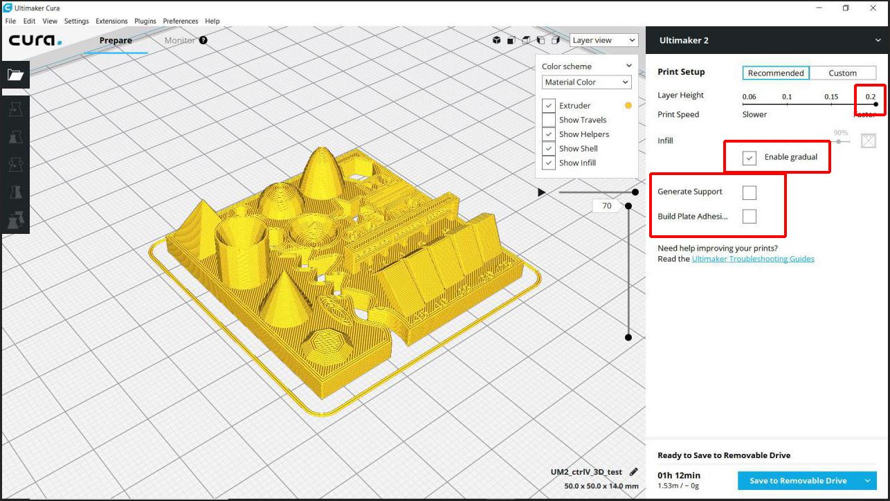
This time we planned to increase the layer height and to see how this will affect the print quality. We changed the layer height to .2 and deselected the build plate adhesive option to remove the unnecessary brim at the curved slot.The print time reduced to 1hr 12min.
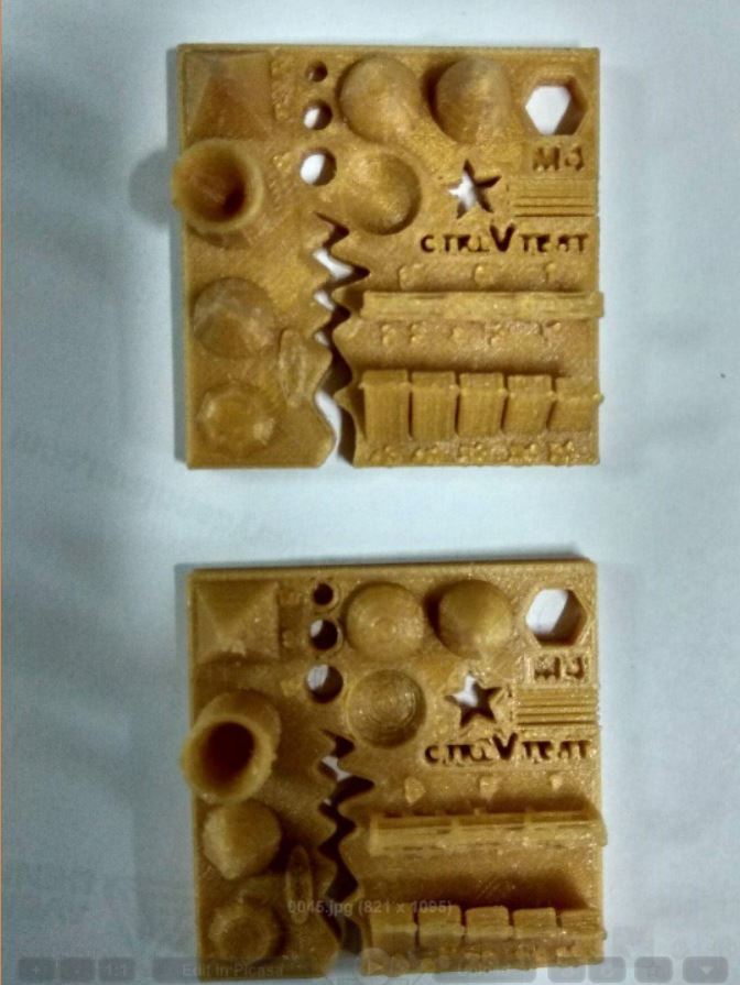
The surface finish for this one didn't come out as good as the previous one but still, it was a decent looking piece. The problem with the bridges and walls persisted and the brims inside the slots were completely removed.
Assignment: 3D Printing
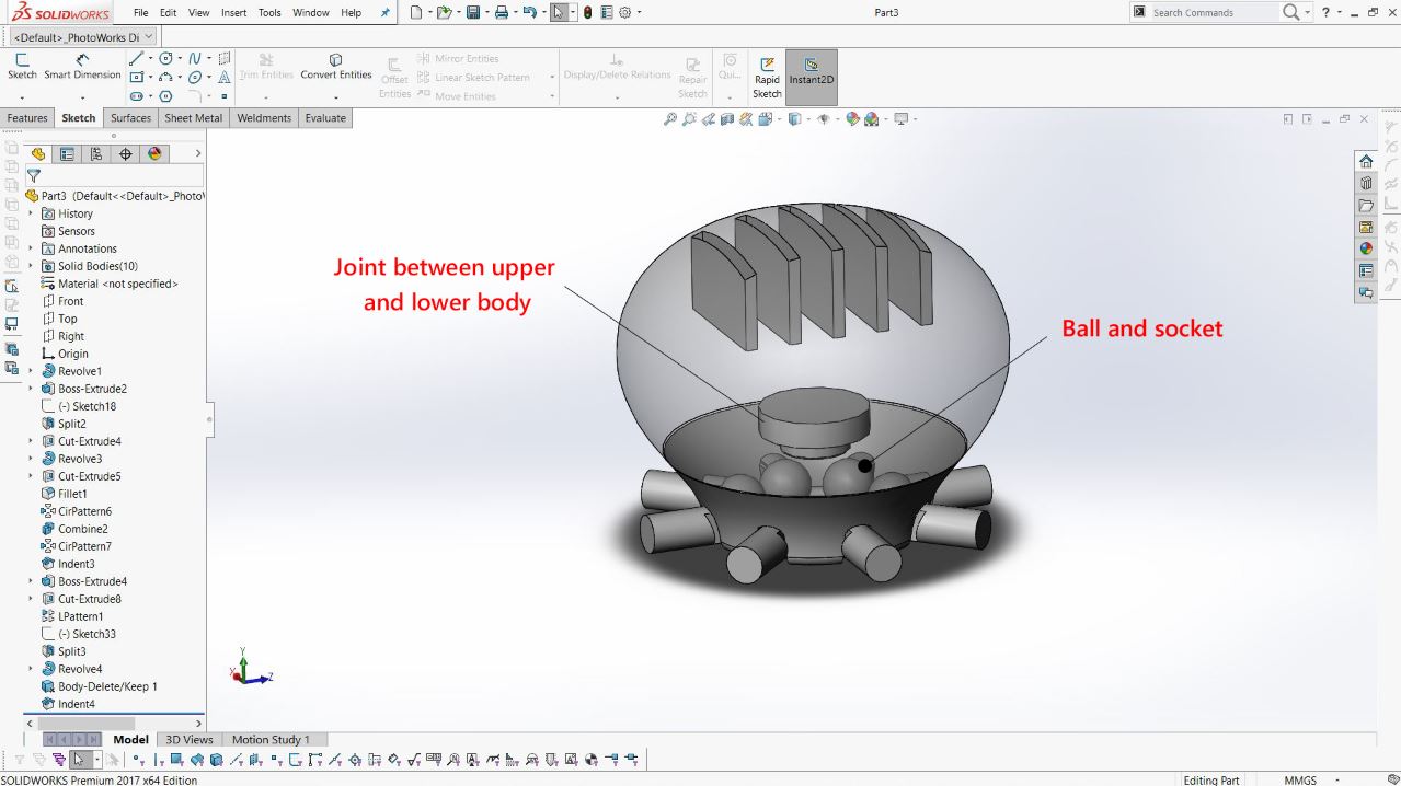
I wanted to make some kind of an SD card holder which cannot be made using any subtractive methods. I started off with a simple design. The idea was to make something like an octopus with some slots in its body (a design I have seen in google some time back) to hold the SD card and to include some ball and socket joints or some other kind of joints in its tendons which cannot be made using subtraction methods. I started designing in SolidWorks and I soon realized that it could take some time to design a completely realistic octopus with separate joints in its tendons.So I thought to make the design simpler by avoiding all the tendon joints and simply using a ball and socket joint connecting the body and all the 8 small pegs. I also included a joint between the lover and upper body so that I can rotate the lower and upper body separately.
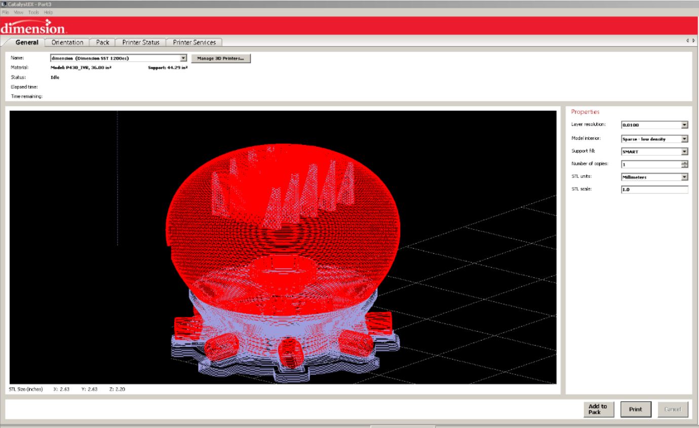
I printed the design in Dimension since the Ultimaker was not available then. The Dimension printer uses another slicer called Catalyst. I opened the file in Catalyst and it generated the support materials automatically. Dimension printer uses a separate soluble material which can be easily removed by putting the printed piece in a dissolving liquid. Hence bodies with a higher surface finish can be made using this printer. In our lab, we use a white ABS plastic material for printing in Dimension. Catalyst has only 3 modes of infill density(low, medium, high).I selected low to reduce the printing time.The materials are automatically loaded from the material cartridges. I only had to put a removable bed into the chamber
After printing, I kept the material in the heated solution to remove its support materials. I kept the temperature at 85 degrees and set the timer for 7 hrs.
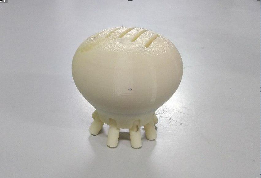
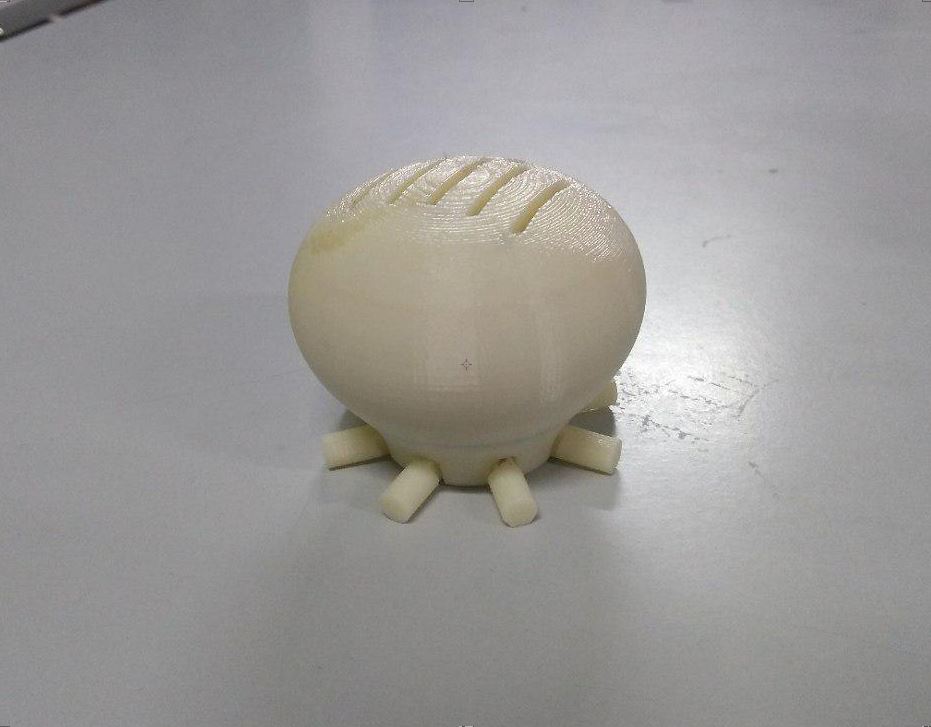
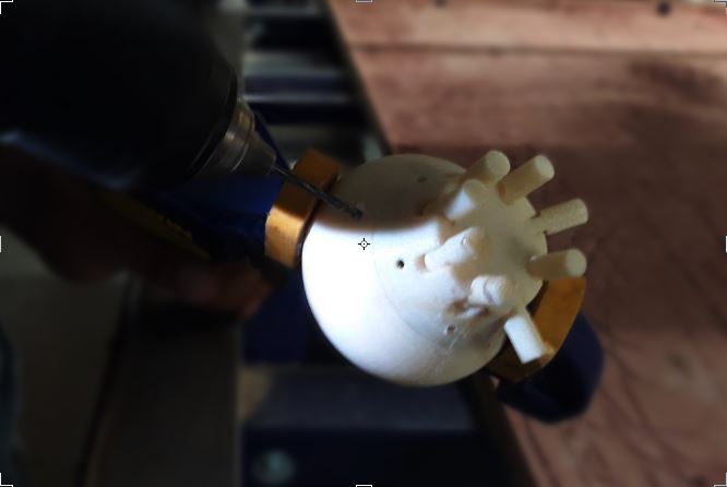
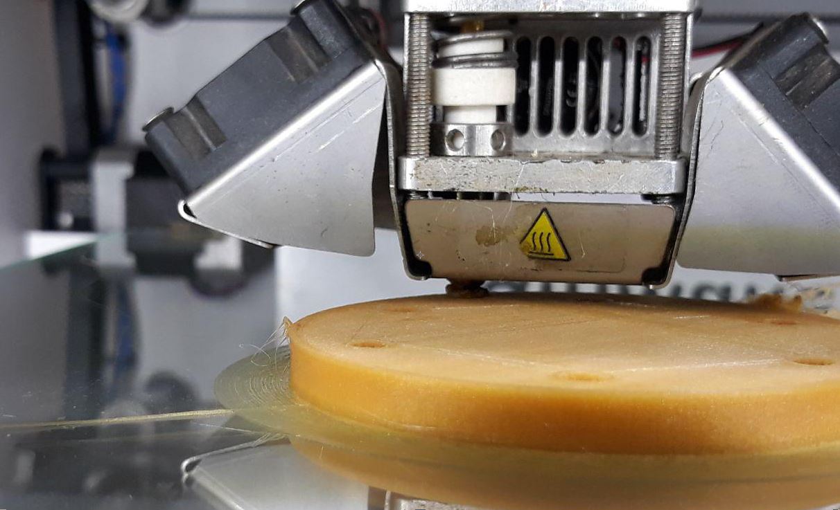
The ball and socket joints were working perfectly but the other one was stuck. I kept it in the solution for some more time but still got stuck and I couldn't rotate the upper and lower body. I noticed that there was still some support materials left in the clearance between those joints and there was not enough space for the materials to flow out. And the clearance was pretty low for the solution to get in. I've already given a .3 clearance between these parts which was a safe value for Ultimaker. To tackle this problem I planned to drill a few holes in these joints so that the support material can flow out.
I kept the material in the solution again .Let us see if the support material comes out this time.
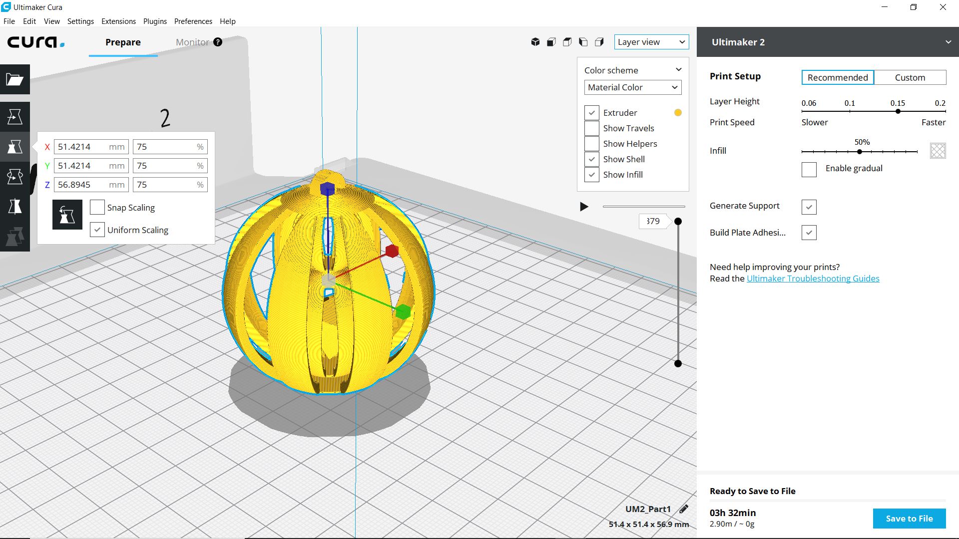
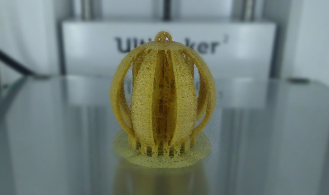
I started designing another file for printing in Ultimaker. I wanted to design some kind of concentric spheres. I started designing in SolidWorks. And I sliced the files in Cura.
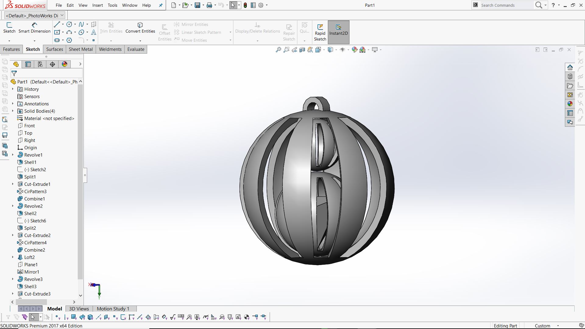
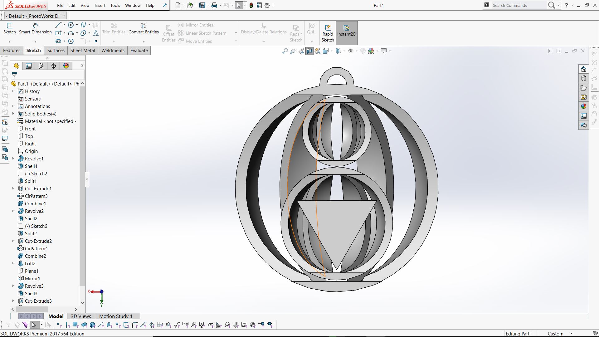
You can download the design files here.
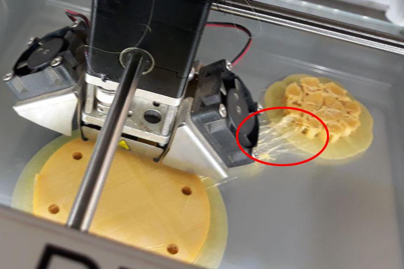
I saved the G code to an SD card started setting up the printer. On loading the print material(PLA) it got stuck. The material was not properly getting inside the tube and it got rubbed away at the material entry point.We had to cut off this material and load it again.After a few attempts, it reached the nozzles. But on reaching the nozzle it got stuck there and the material was not purging. I tried changing the nozzle temperature and increased it to 220 degrees to purge the material. But it was still stuck at the nozzle. Then we removed the material housing and tried pushing a small piece of material through the nozzle. We also tried different materials. Finally, I cleaned the nozzle using a thin wire and all the material that was stuck in the nozzle finally purged.
I started printing But there were gaps between adjacent layers. And the materials were extruded in a non-uniform way. I tried switching off the AC directly above our printer to check whether it was affecting our print anyway. No change was seen in the print though. I went on with the same print as it was already late and I didn't have any more time to troubleshoot.
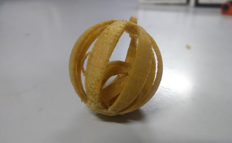
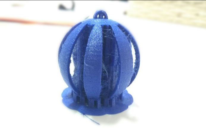
As I expected, the quality of the print was pretty bad and few of the components broke while removing the support material.
I tried printing the material again by making slight changes in the Cura. I changed the layer thickness and tweaked a few values. I also included my friend Salmans file to print them together.
But halfway through the printing the printer got stuck and an error was shown :(
I also noticed that when 2 components are printed at once, the nozzle moves from one component to other after each layer and it can lead to extended materials in the nozzle path and affect the print quality. To avoid this one has to set a print sequence and select an option to print one after other in the slicer.
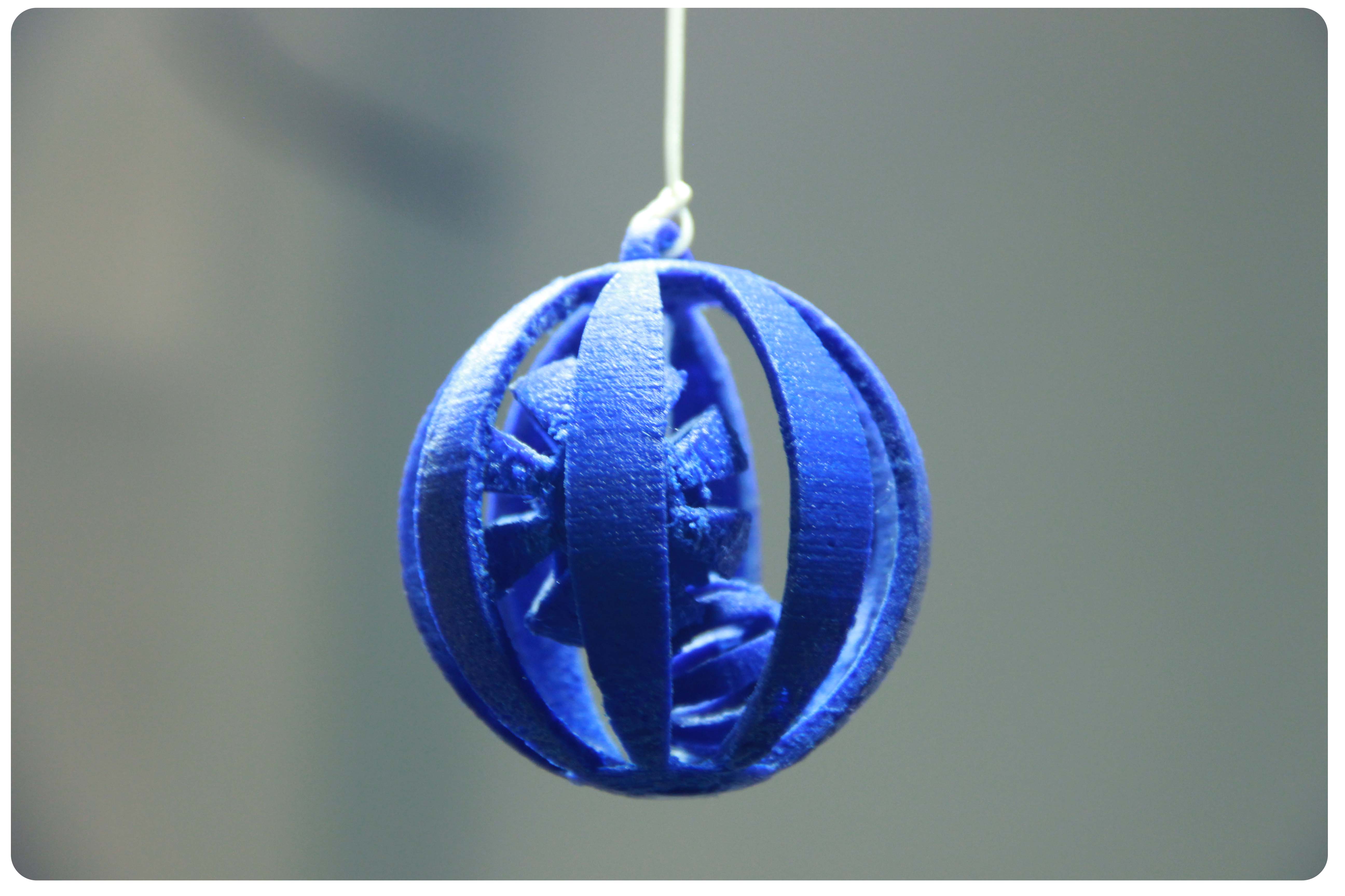
To avoid further complications I printed each component seperately with a different material
After some sanding and filing my model was ready to go :)
Assignment : 3D Scanning
I started 3D scanning using Kinect XBOX 360. All the drivers and software were already installed in the fab lab PC. I used K scan 3D software for the scanning purpose. In K scan we set the no of- scans and the interval between each scan. I adjusted the X, Y and Z value in order to map the object precisely. I started by scanning a fire extinguisher at Fablab but only one side of the scan was seen in the combined scan.Also, it was not able to detect the black color at the tip of the Fire extinguisher. So I thought to scan my face instead. I set the no of scans as 71 with a 3 sec gap between them. And I slowly rotated at uniform intervals in order to get a uniform scan.
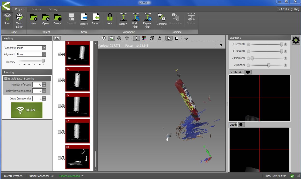
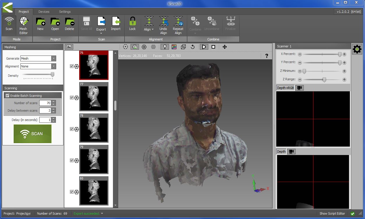
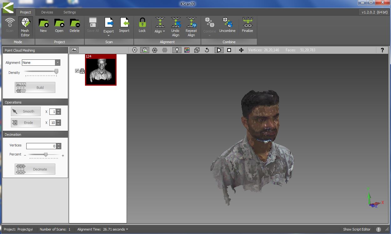
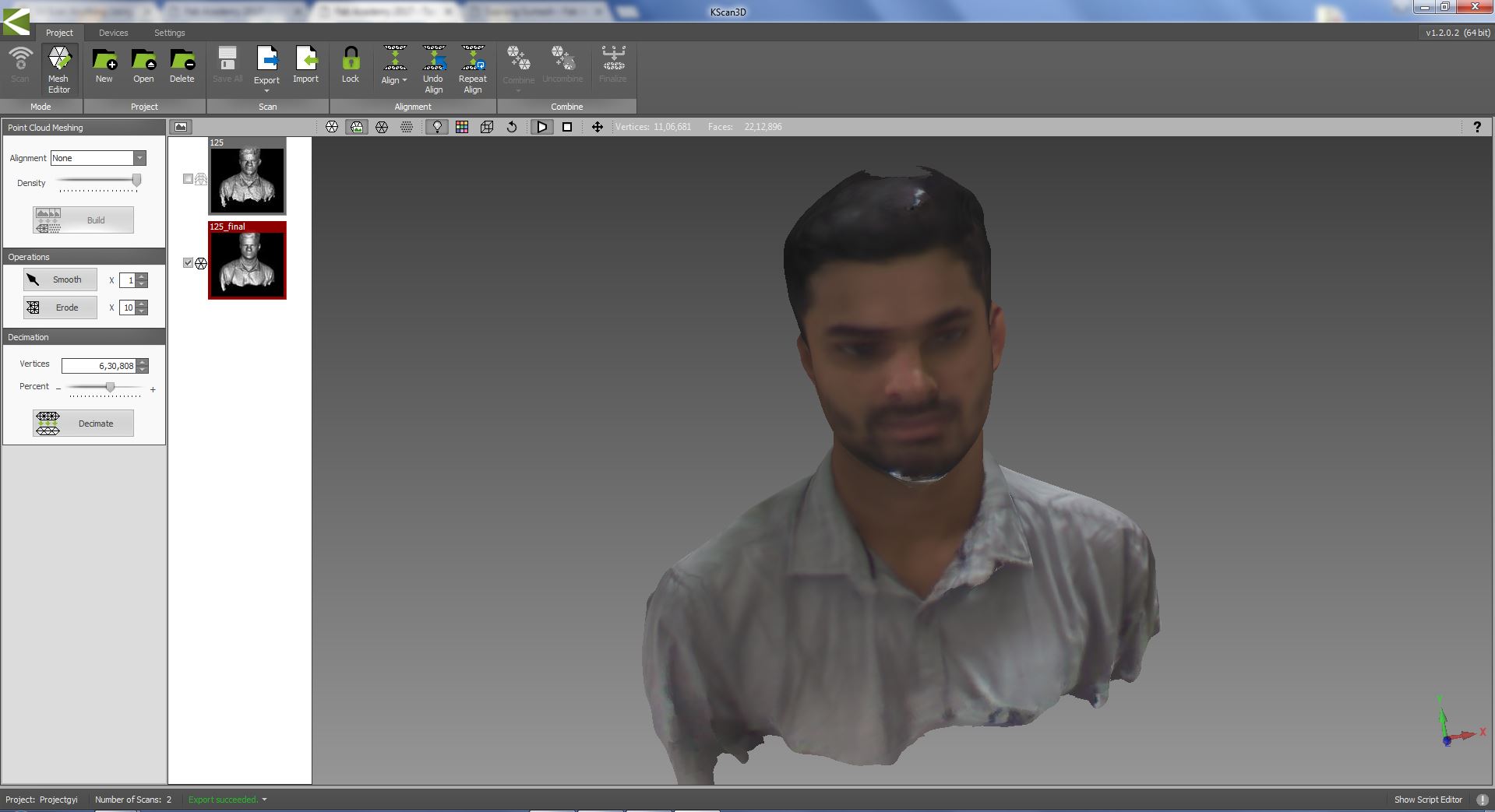
All the scanned files were aligned by clicking on the align button. This was then combined into a single file by clicking on the combine button. To get a much-finished file click on finalize to get the finished and final file. I then exported it into STL format to further edit the meshes and fine tune the scanned files.
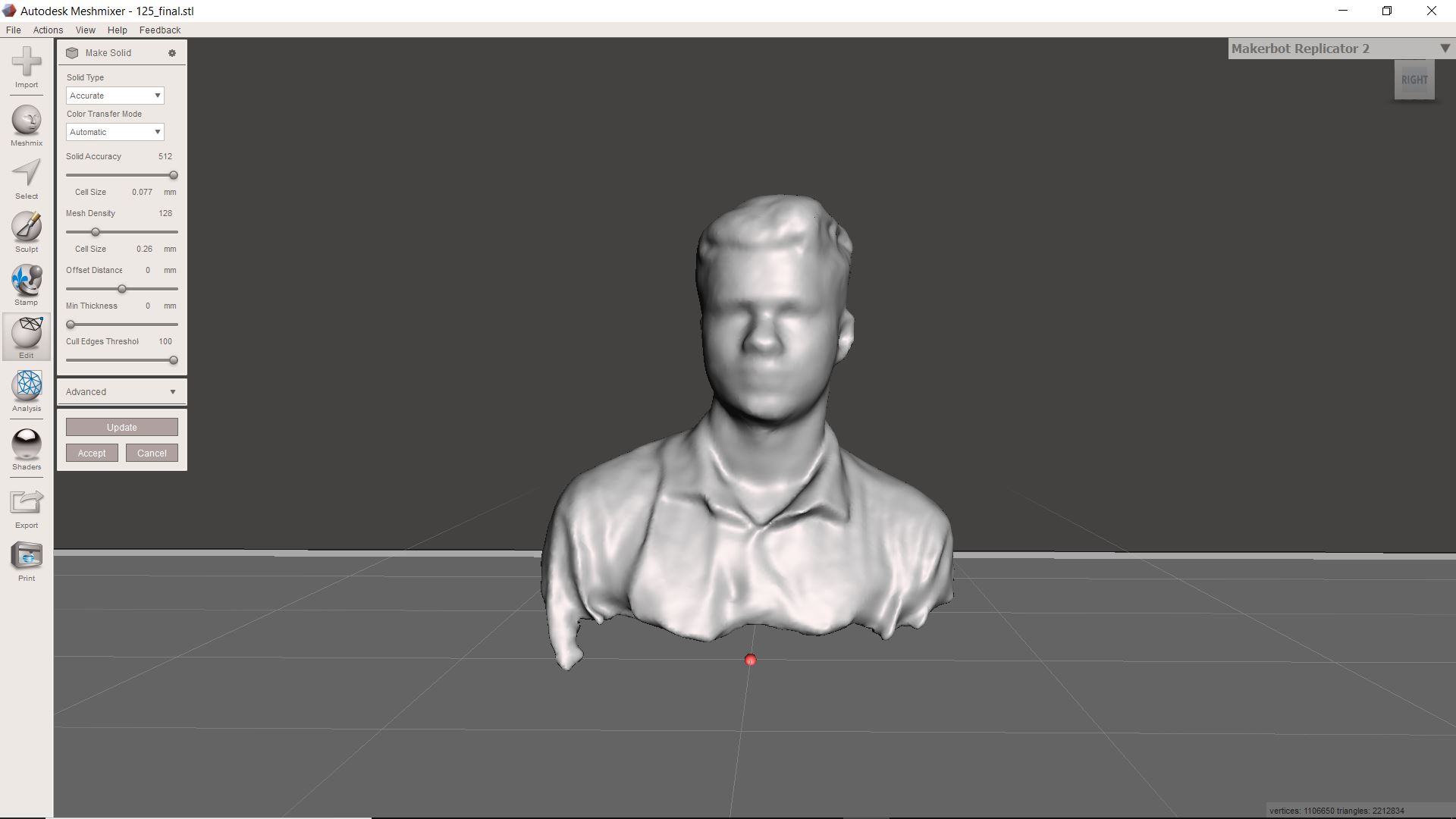
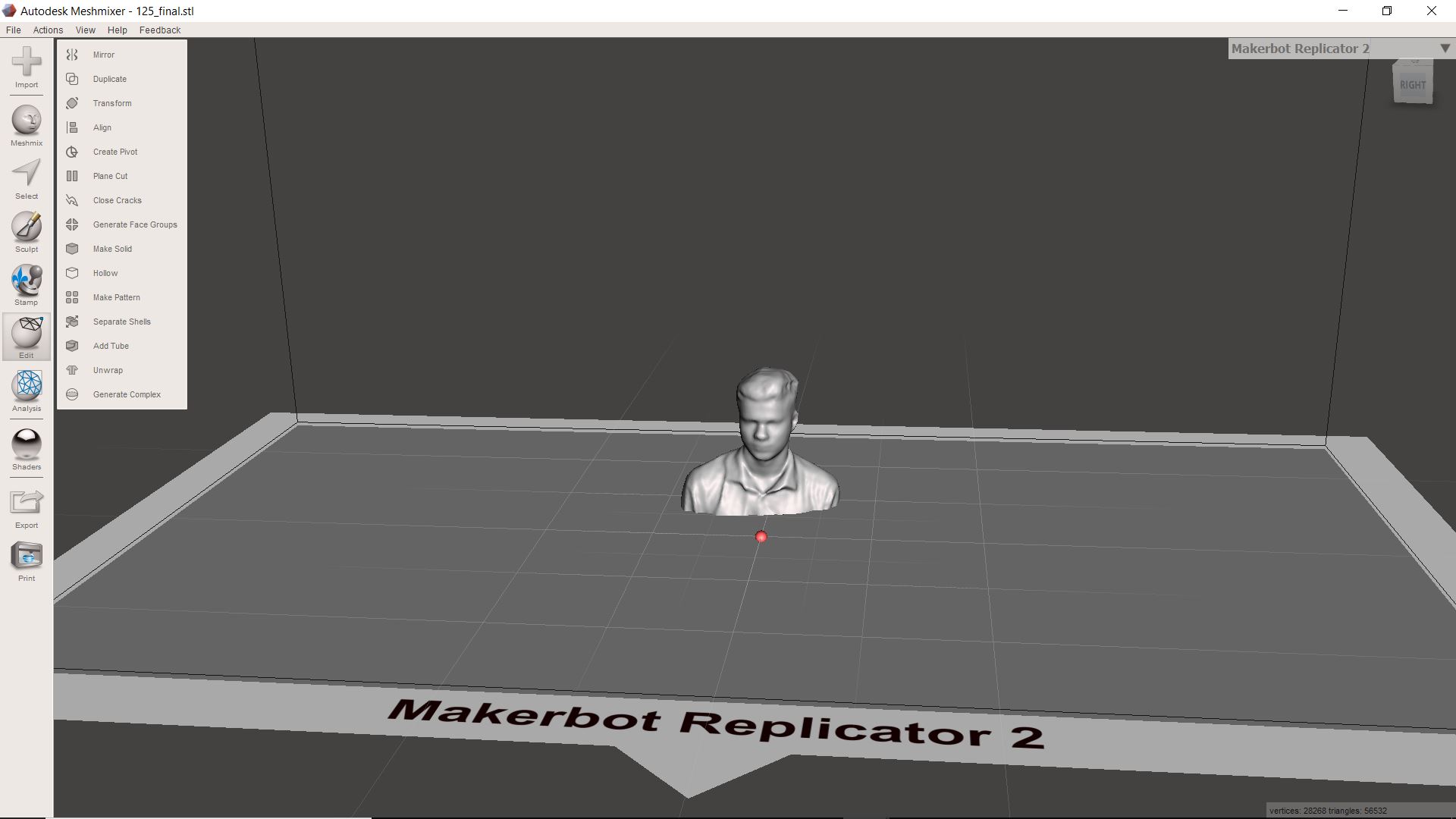
I then opened the files in Meshmixer. Mesmixer is a software from Autodesk to easily edit the STL files. There were some gaps in my scanned files in the top portion of my head. I filled this gap by converting the file into a solid file. I made the bottom portion flat using the plane cut option so that I can 3D print this file.
Download the design files here.
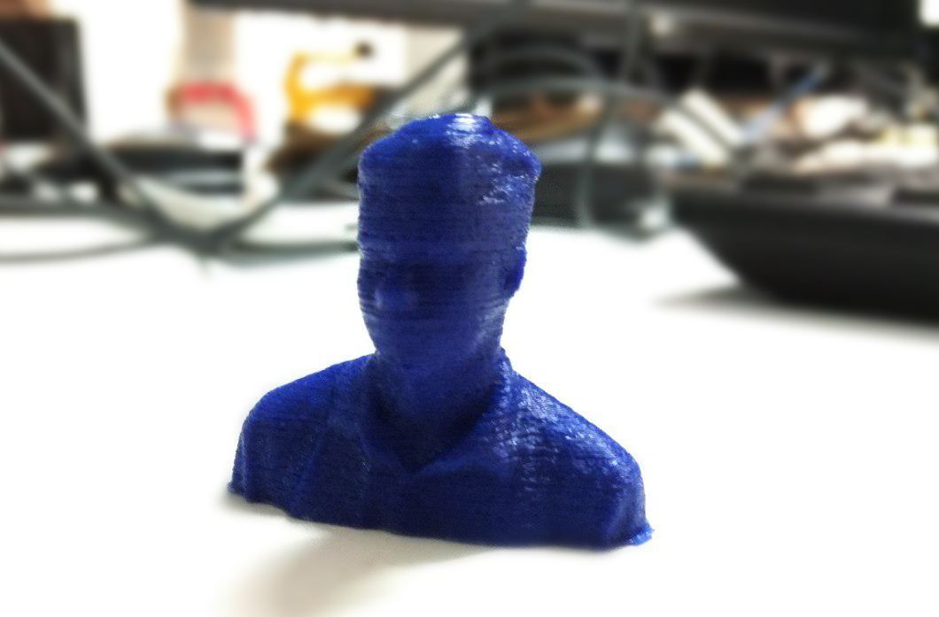
I sliced this file using Cura and me and my friend Suhail printed it in Ultimaker.
Using Modella
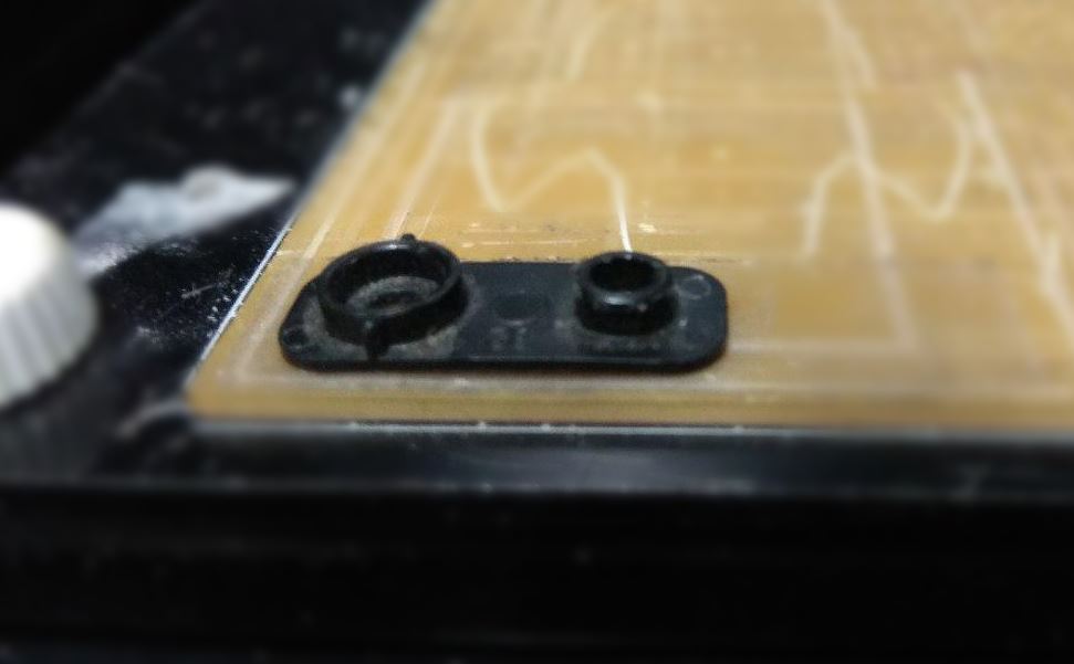
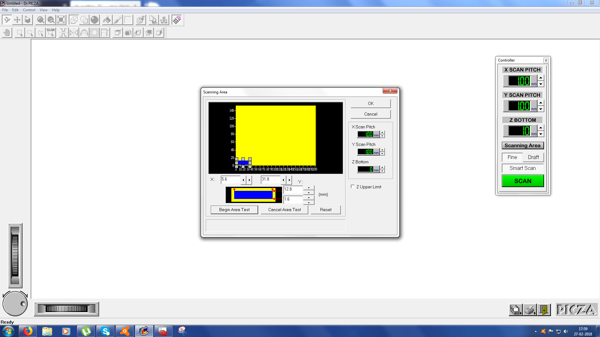
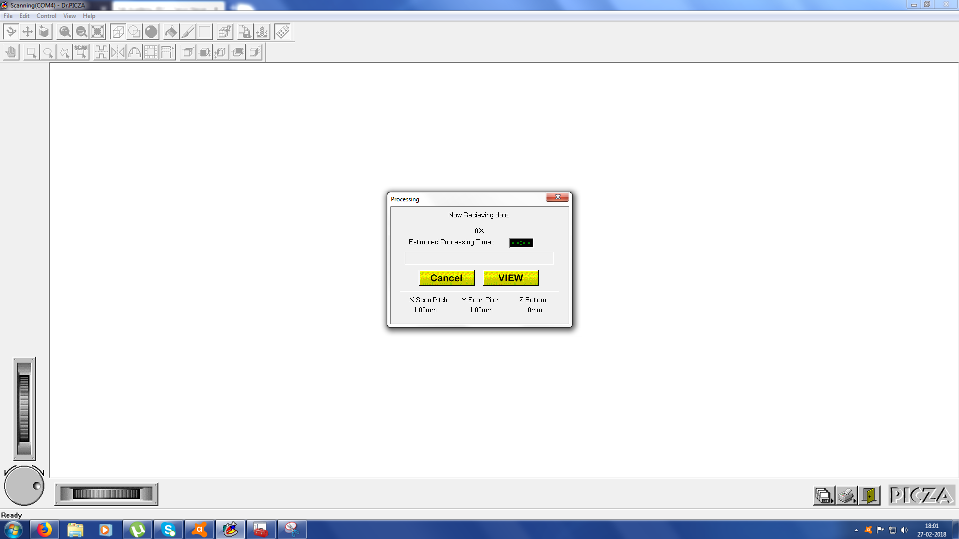
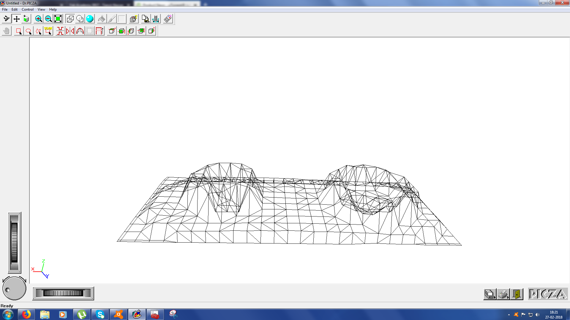
We can also scan using Modella MDX 20 milling machine from last week. We have to replace the milling machine with a probe which will move up and down and calculate each point in a 3D space. We use a software called Dr.PICZA. Here first you have to specify a scan area thereby avoiding unnecessary time wastage.After specifying the scan area I tested it. You set the X, Y and Z bottom values there. I set the Z bottom value as zero. I attached a small material to the bed using a double-sided tape.On clicking the scan button the machine automatically determines the 3-dimensional points of the objects using the probes.But this one is a tedious process and are prone to errors.
Download the design files here.
