
Week Six
Assignment
What I did
Introduction
This week 'Electronic Designing' is a completely new topic for me. I've never done something like this or something even close to electronic designing. So there was so much to study this week. Niel gave us an introduction to the basic electronics and the common practices used while designing.
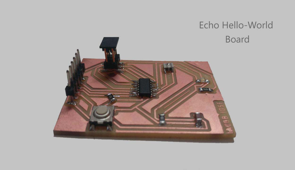
This weeks assignment is to redesign Niels echo hello-world board and to add two components to it (LED and Push button) and to completely redesign the board test the design rules and to make it. We also had a group assignment to use the equipment to test the microcontroller circuit.
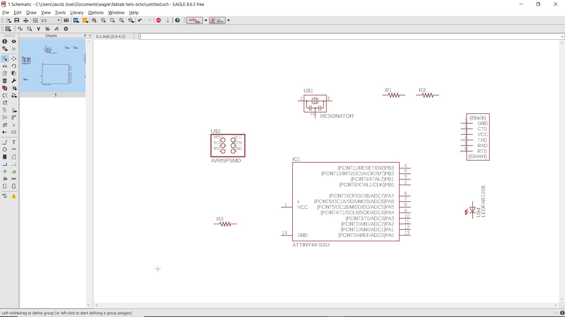
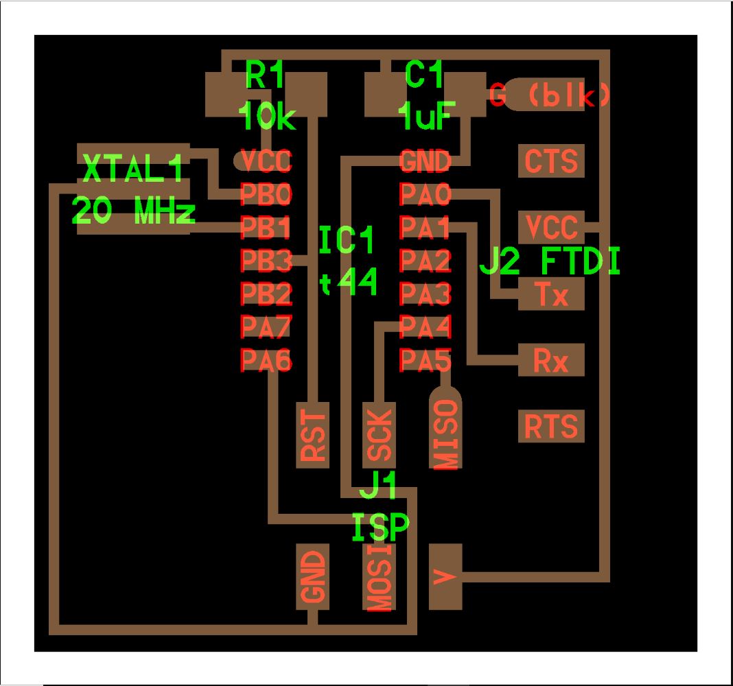
I started with the basic electronics.The default hello world is here.I need to add a push button and LED to this existing design and resistor to ensure only the right amount of current passes through the LED. The Microcontroller( Attiny44) already has an 8Mhz internal clock. But we are adding an extra 20Mhz resonator for more accuracy and precise clock applications.Our instructor gave me an idea about the basic electronic fundamentals like Ohms law and Kirchoff's Law . I also referred this article to know more about filter capacitors.
Pull Up and Pull Down Resistor
I read about pull down resistors from this article.A pull up or pull down resistor is used to remove the floating voltages and ensuring higher or lower states in the microcontroller pins so that it can read the values accurately.A pull-up resistor ensures a high state and a pull-down ensures a low state.
Using Eagle
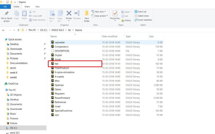
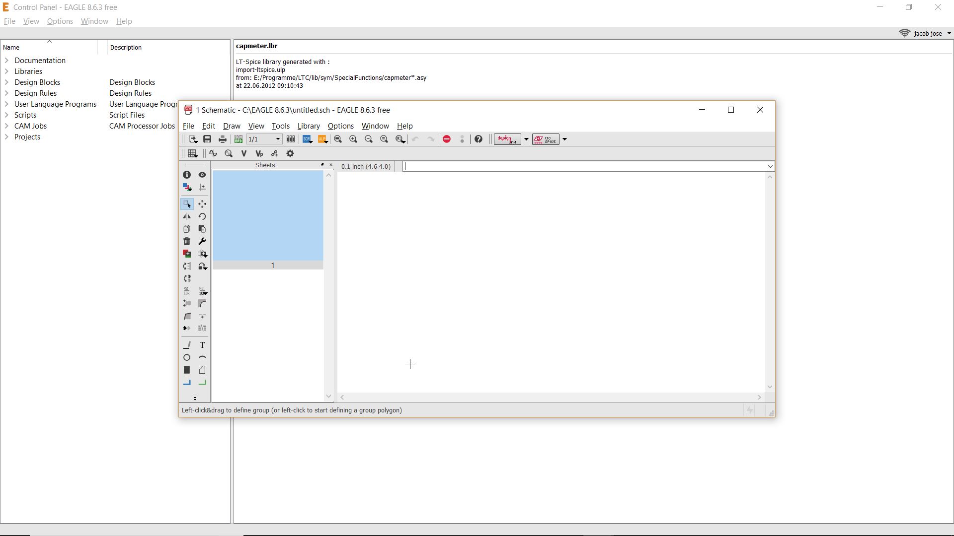
I planned to design my board in eagle . I downloaded eagle from the official website and logged in using my Adobe account. The first thing I did was to add the Fab libraries. I referred the steps from this archive. I downloaded the fab library from here .I then copied this file to the lib folder in the eagles install location.
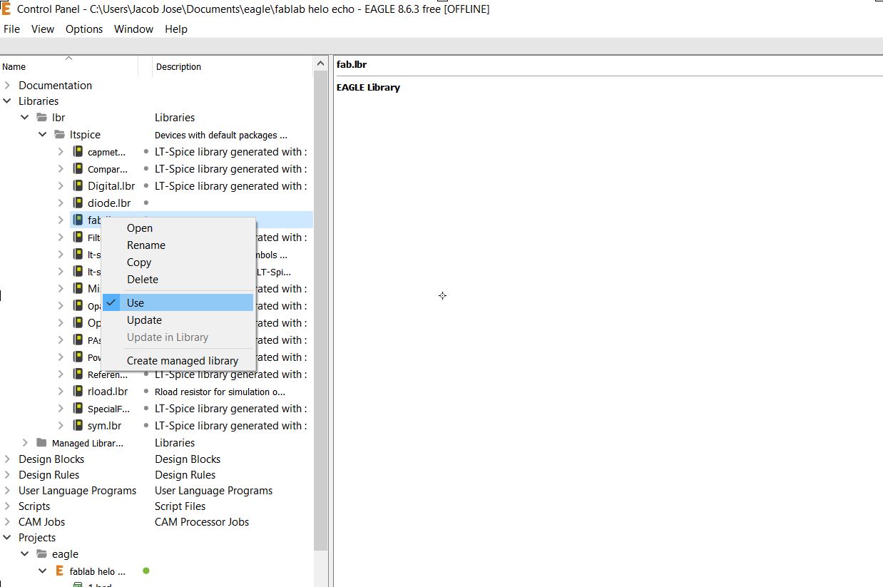
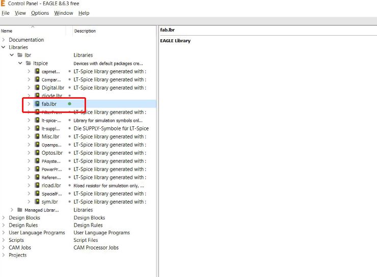
To use these library files we have to first activate them by right-clicking on the fab lib file and selecting the use option. One can see a small green dot beside the library file once it's activated.
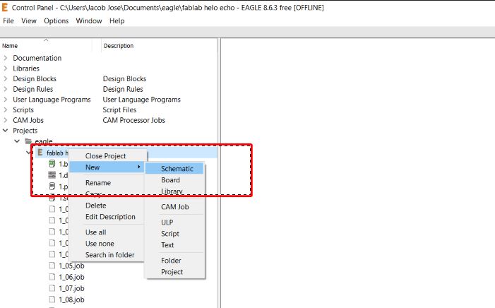
The next step was to start the Schematic drawing. For this, right click on the project file select new and schematic from it.
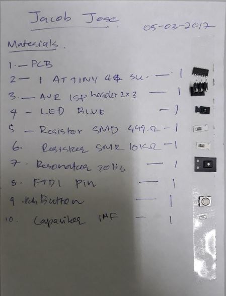
The components I used were:
Then I added all components using the add command. All the required materials are available in the fab library. All the components can now be connected using the net command. To reduce the complexity we can label the pins which we use often like the VCC and GND. Use the command label for it. To change the default name of the labels use the command name and click on the label which you have to change. I first connected the components without a switch and then the switch was added.
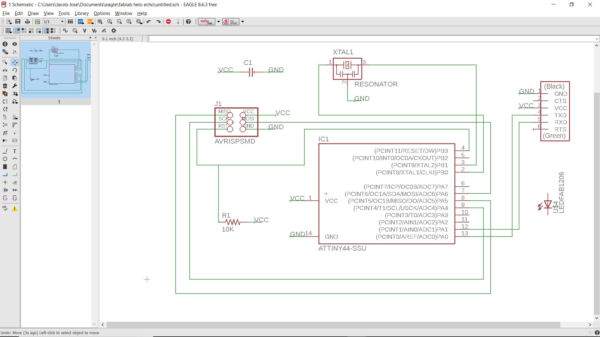
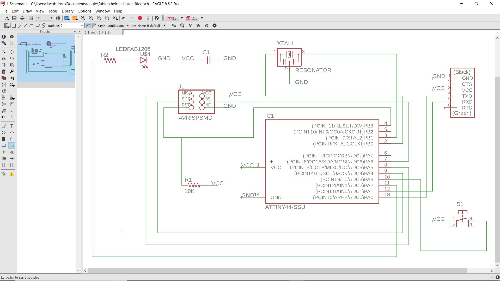
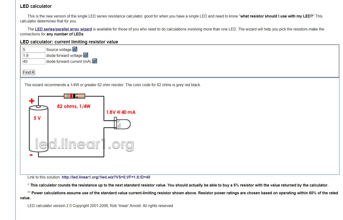
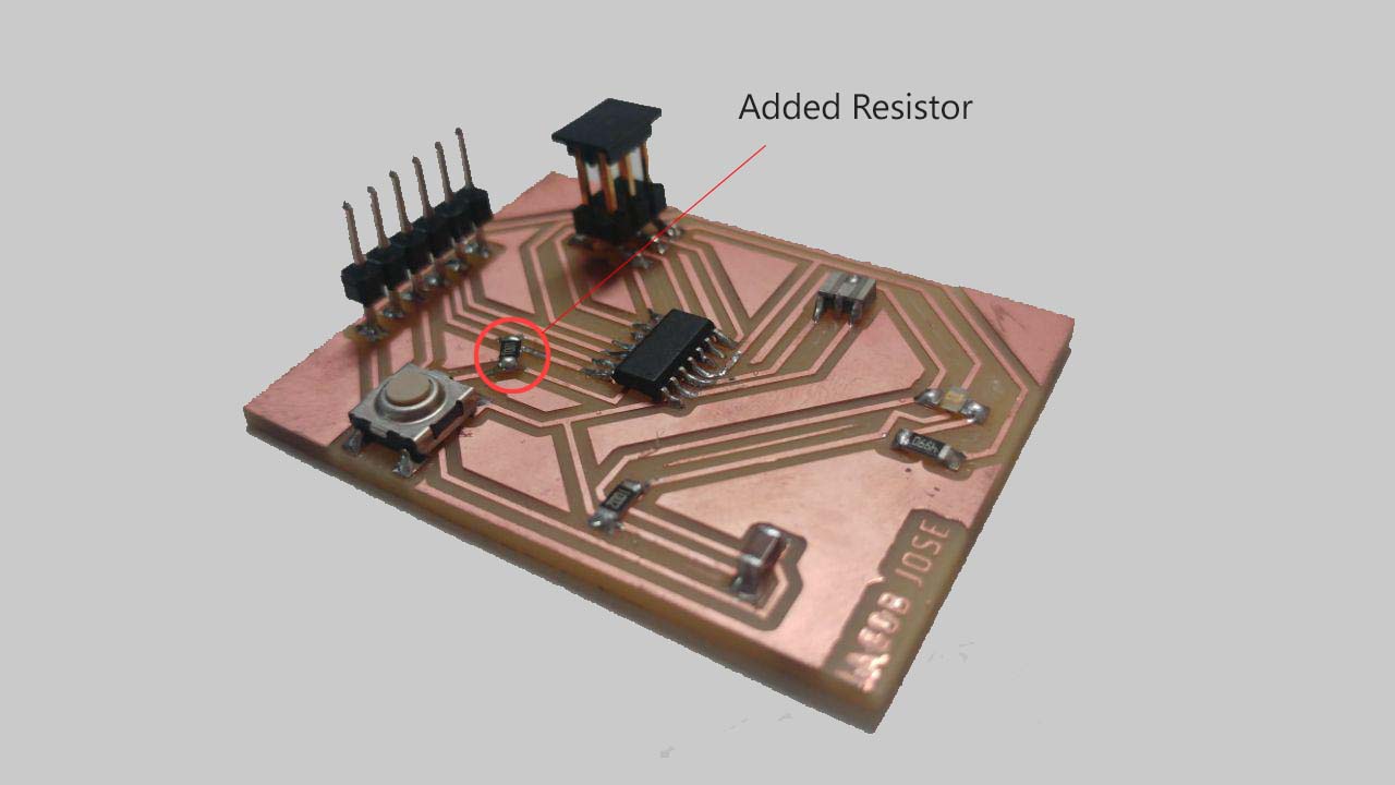
But I made a mistake that I forgot to add the pull-up resistor. I only found that after soldering the components. So I added a 1K ohm resistor to the ground and switch later.I also had to calculate the resistor for the LED. For calculating the resistance I used this website. The resistance was calculated to be about 88 ohms. I used a 499-ohm resistor to be on the safe side.
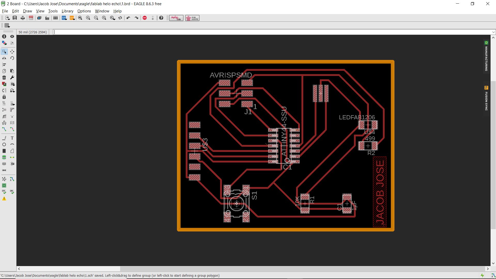
The next step was to make the traces of the board. For this, we have to select the switch to board button in the toolbars.
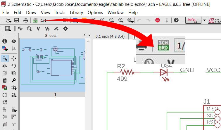
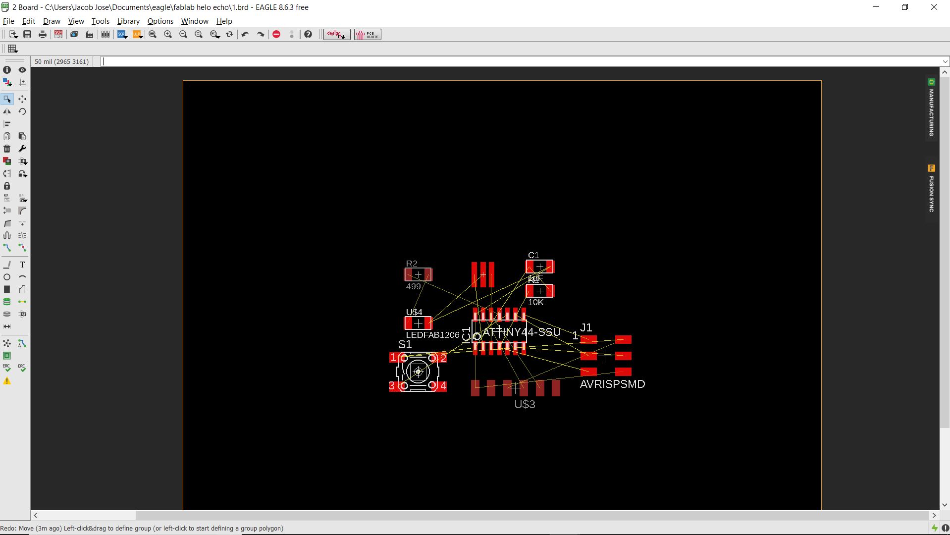
Then we can see all the components and its connection here. We have to place each component by clicking and dragging them to appropriate arrangements. The next step is to root the connection lines. We can do that in two ways. One is manual rooting and other is Auto rooting in which the computer automatically does the rooting for you.
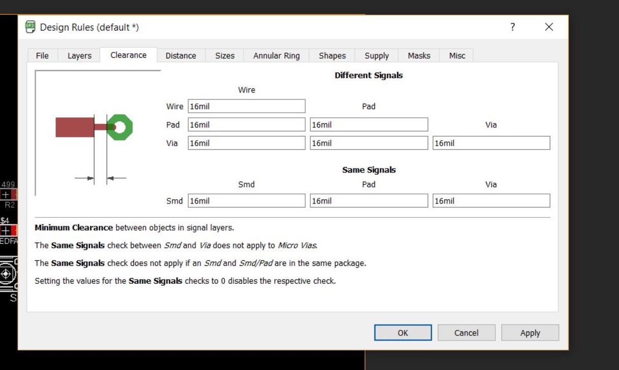
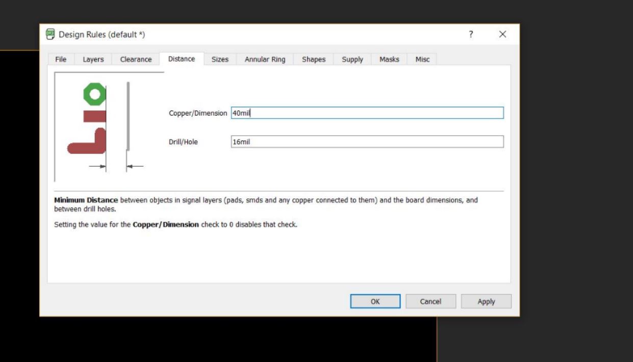
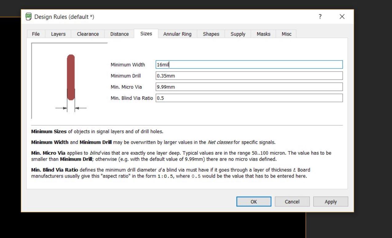
Before rooting we have to first specify the design rules for that click edit select design rules . Now you can make necessary changes in your PCB design like the width, clearance and distance.In our case, we are using a 1/64 bit. So the minimum width comes around 15.625 mil so we take a safe value of 16 mil. Once the necessary changes are made we can move on to the rooting section.
I went for the auto rooting first. I selected the auto rooting icon on the left side of the toolbar for it. You can make the effort to high to get more no of possible roots.
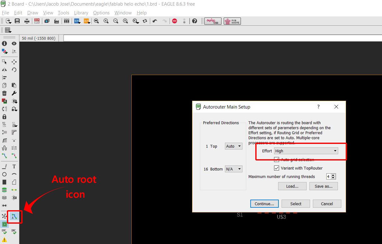
On auto rooting, none of my possibilities reached a 100%. SO I rearranged the components and tried again. After trying a few different arrangements I finally got 100 %. I then made a few edits in the design using Rip up tools by changing a few 90-degree corners to chamfered ones.
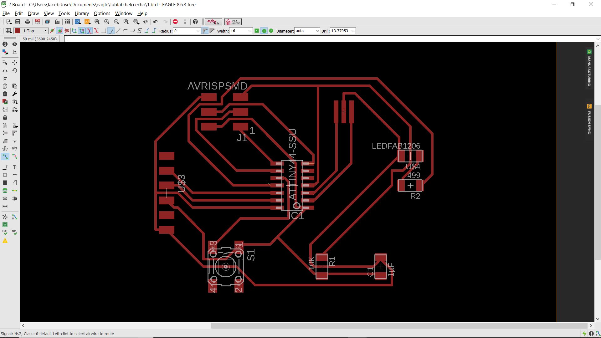
I then adjusted the boundaries to get a cut figure.The width of the cut line was changed to 32 by right-clicking on the line and choosing the properties option. This has to be done because only then the machine can detect the lines.I also added my name to the traces using a Text tool on the left side of the window
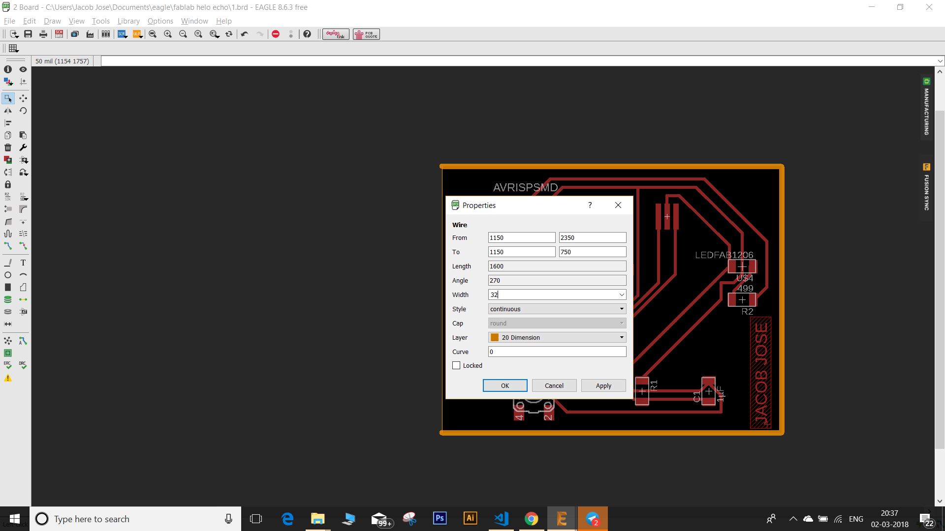
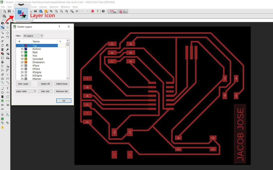
Next, I selected the layer icon and selected the red color to separate it from the cut layer and I exported it as a PNG file (PS: Remember to tick the monochrome option). The same was done to obtain the cut file as well.
Download the Eagle design files here .
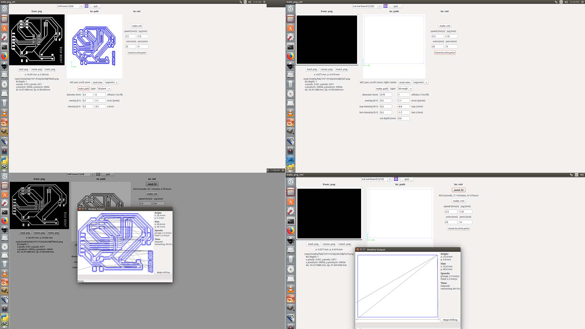
Milling PCB
Since the design was ready it was time to mill the PCB and start making our board. I followed the same procedures from week 5 to mill the board Modella Mdx 20 Milling machine.
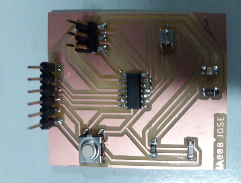
The Milled PCB looked like this
Required components were taken from the inventory. I then carefully Soldered them to the board. I also checked for continuity and bridges in the circuit using a multimeter. Everything seemed ok.
Problems faced and troubleshooting
The first problem I faced was while milling the cut trace. The machine didn't detect my cut trace. This was due to a small mistake I made while exporting the PNG file.I forgot to tick the monochrome option while exporting the images and the files were exported in default orange color and the machine couldn't detect this. I exported another image and fixed this problem.
The 2nd mistake I made was with the schematics. I forgot to add the pull-down resistor. Since I've already soldered the components I thought to add a 1 Kohm to this board externally some other way. Luckily my Groundline was next to the switch so I added the resistor from switch to the ground line and this fixed it :).
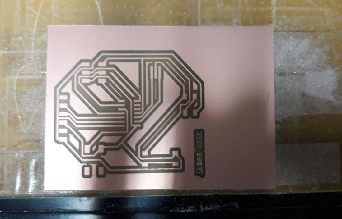
Finaly the hero shot
Testing
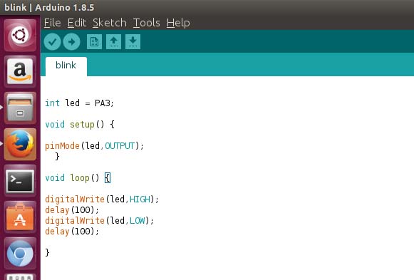
Next step was to test my board. I used Arduino IDE to flash my board. I downloaded the software from here .I connected my fab ISP to the echo hello board using a ribbon cable and then connected the fab ISP to the PC.
I'll be getting into the details of programming in the following week. Now I am just testing my board using a simple program to blink the LED using the following code.
Group Assignment
This weeks group assignment was to check a microcontroller circuit using the test equipments in our lab
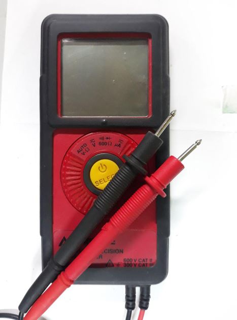
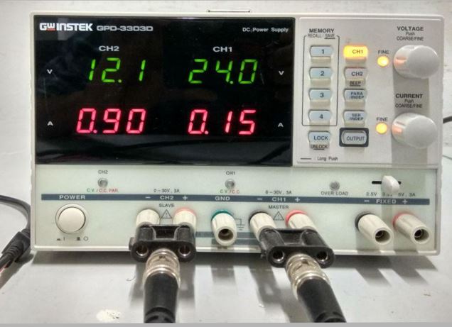
The different test equipments we had in our lab was Multimeter, Dual channel Power Supply, Digital Oscilloscope and a Function Generator.
Its a simple straight forward machine to measure basic current voltage and resistance values. It is also used to check the continuity basic things in your board.We have a Amprobe PM55A pocket sized multimeter in our lab.
In our lab we have a Gwinstek GPD-3303D power supply using which we can supply the power in required voltage and current.We used to power up salman's PCB and to check if his LED connections are correct.
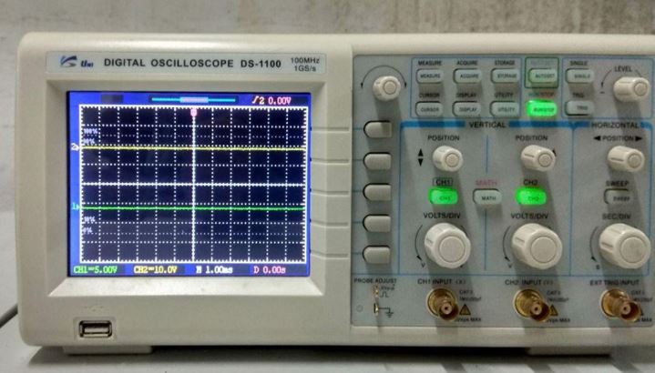
It is much more complex machine to analyse different signals and to see their timing and shapes.We tested the pulse width modulation in Attiny 44 using this Oscilloscope.
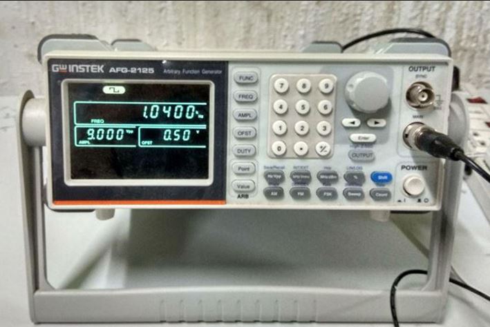
A funtion generator is a device used to generate electrical waveforms.We have a AFG-2100/2000 Series Arbitary function generator in our lab.We connected the output of the function generator to the oscilloscope to see the variation in signal with different parameters.
