
Assignment :
Design a machine that includes mechanism+actuation+automation.
Build the mechanical parts and operate it manually.
Actuate and automate our machine.
This week we have we have to make a mechine .We have to Implement some of our previous week learnings to create a functional machine that must have some sort of machanical movement , Actuation ,motorcontrolls and a controll algorithem.For this week we have to complete the mechanical assembli.We have to impliment the control mechanism during the next week assignment.
We decided to make a machine which will be help full to the lab . We wanted to create an inventory mangement robot. The machine could be able to manage the electronic assets of the lab . If someone wanted to have a purticular component he can give that information to the machine using an android app .The machine will go through the inventorys and took the component and place in an accesable platform.
We divided all the works in between the students
Since I was familier with the designing of some machines before I decided to go for the machine designing parocess .I choose the Autodesk Fusion 360 platform to design our machine .It was a painstaking process I almost took 4 days to complete the designing itself .Since everybody contributed to the manufacturing process we could able to complete the machine on time.
This is the front and side view our robot
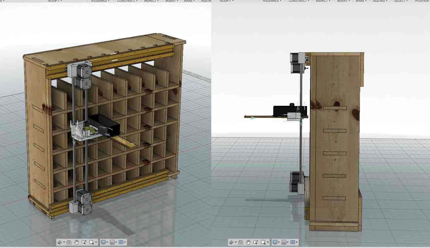
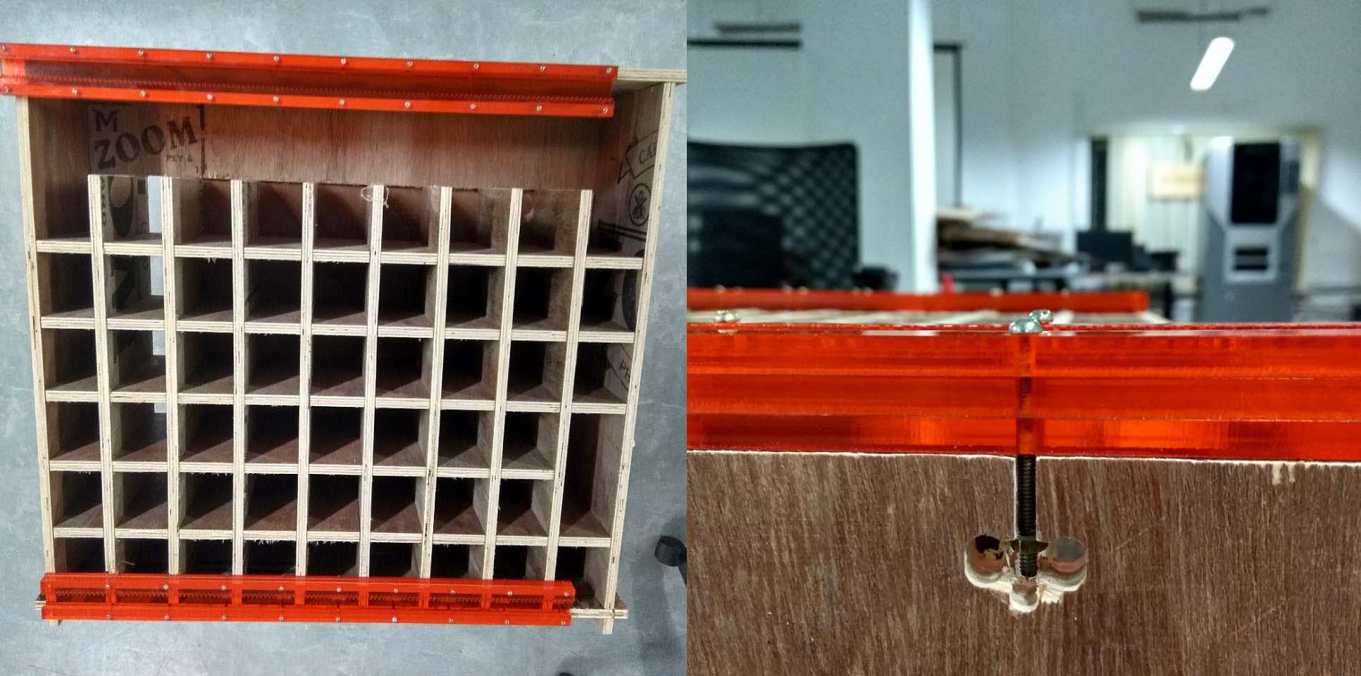
The X axis which moves the machine in horizontal direction are suspended in 2 linear rails which are made up of laser cutted acrylic .The rail also has an integrated rack and pinion which are driven by 2 nema 17 stepper motors.One for top and another for the bottom rails.We choosed ralis and racks because we wanted our machine to be scalable so that in future we could add more shelfs to it in parallel. If we used pulley or lead screw we can't do this.Since I was doubted about the torqe demand for the verticsl movement I choose 2 nema 17 stepper motors for the vertica movement also .For the vertical motion the endeffector was driven by a belt and pulley mechanism. Insted of the rails which we used for horizontal movement the vertical movements we choose smooth rodes
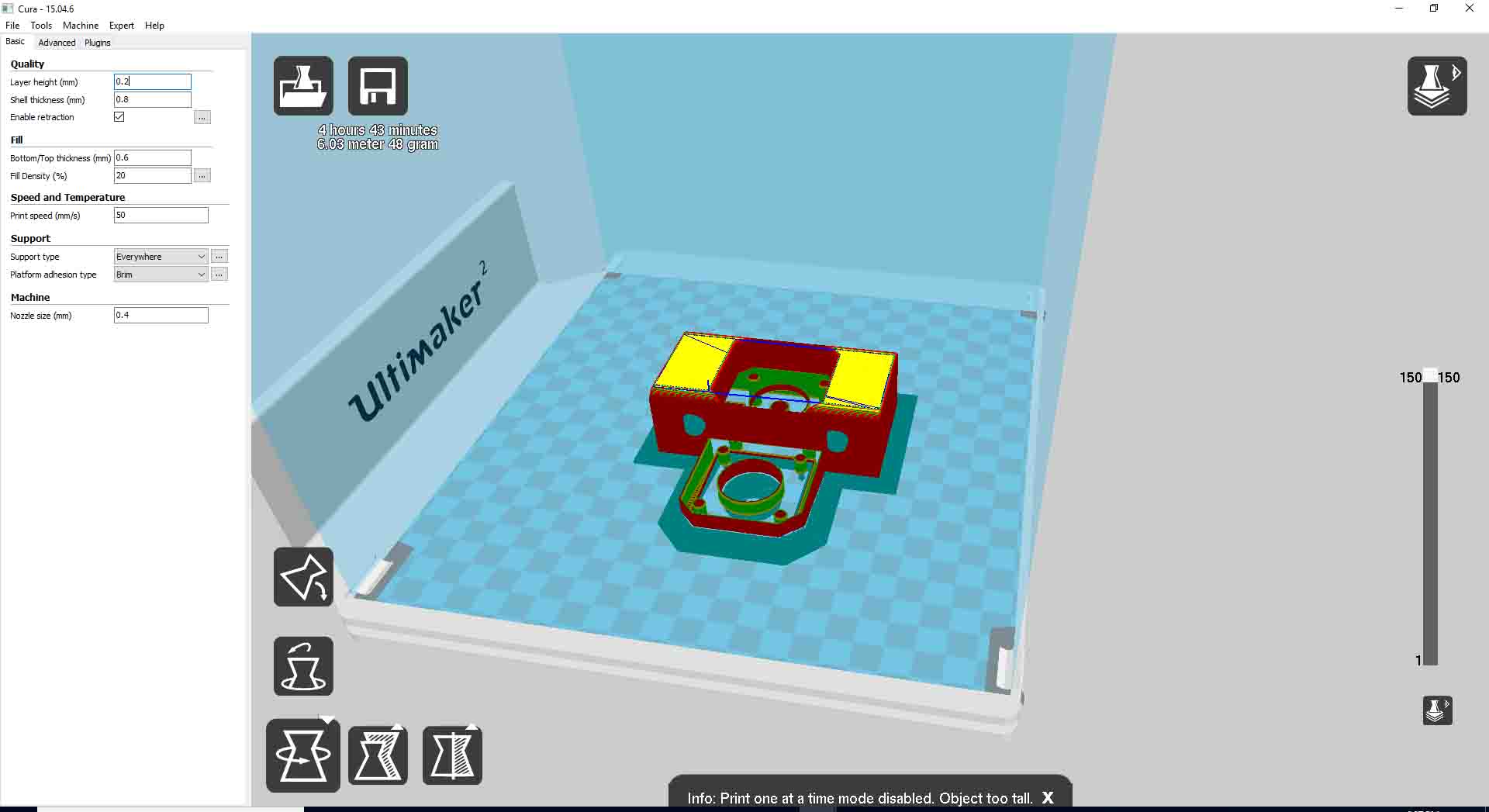
We used 3d printer for printing our end effector and 2 Stepper holders at the top and bottom.To make the rail,rack and pinion and the extending platform at the endeffector we used our lasercutting machine.
This is the stepper holder opened in cura
These are the laser cutted components.
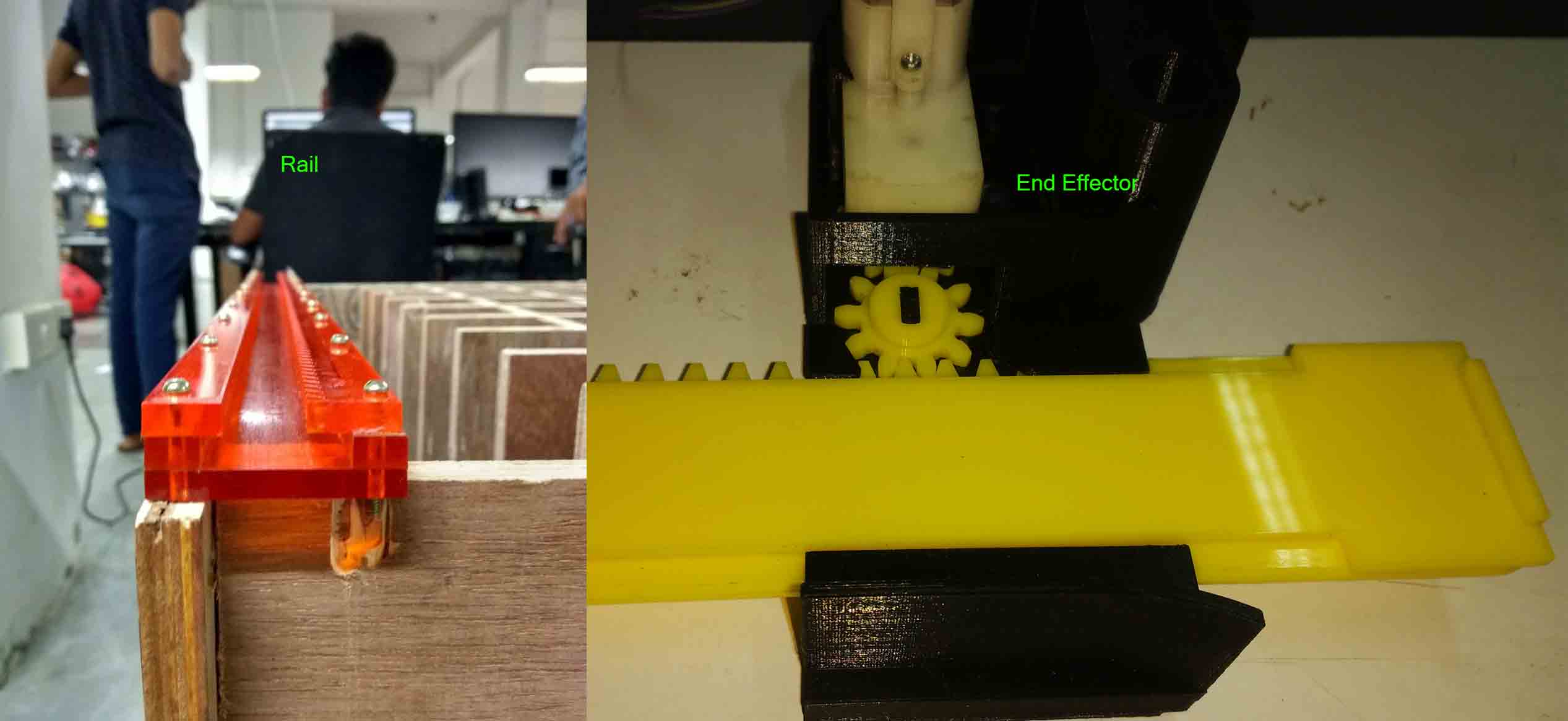
The rail is anchored to the shelf with nuts and bolts .It is tighted to a pocket made in the top and bottom plates of the shelf
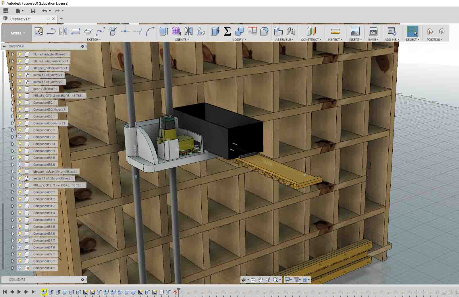
To attach the belt to the end effector .We made a projection on the back if the end effector and substracted a model of the the belt from it . Also I just made some clearence by presspulling the surface.
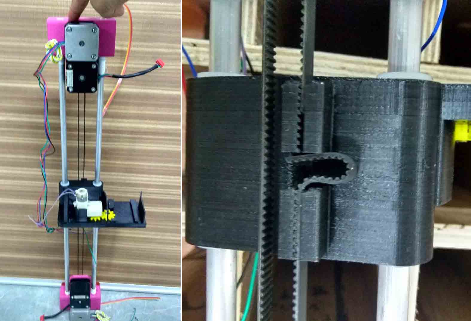
This is how our rail will work,
Jacob testing our vertical motion components.
This is our completed cad model
This is how me and jacob completed our machanical designing .To know more about our project you can find it in our group assignment page . Our project is a combined effort of me and my fab mates . So there you can see how salman and suhile made our pcb and motion control systems and also how hari and justine complete all these machining processes.