Assignment :
Group assignment: characterize the specifications of your PCB production process
Individual assignment: make an in-circuit programmer by milling the PCB
I have some previous experience in PCB manufacturing using etching process .This is the first time i am using a milling machine for pcb manufacturing.So i am realy excited to exploit this opertunity.

| Work area | 203.2 x 152.4 mm |
|---|---|
| Z stroke | 60.5 mm |
| Spindle speed | 6500 rpm |
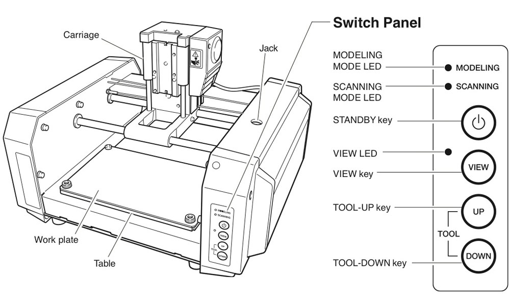
Modella MDX 20 is just like any other CNC mechine. We use the same fab modules which we used in vinyle cutting for milling also.
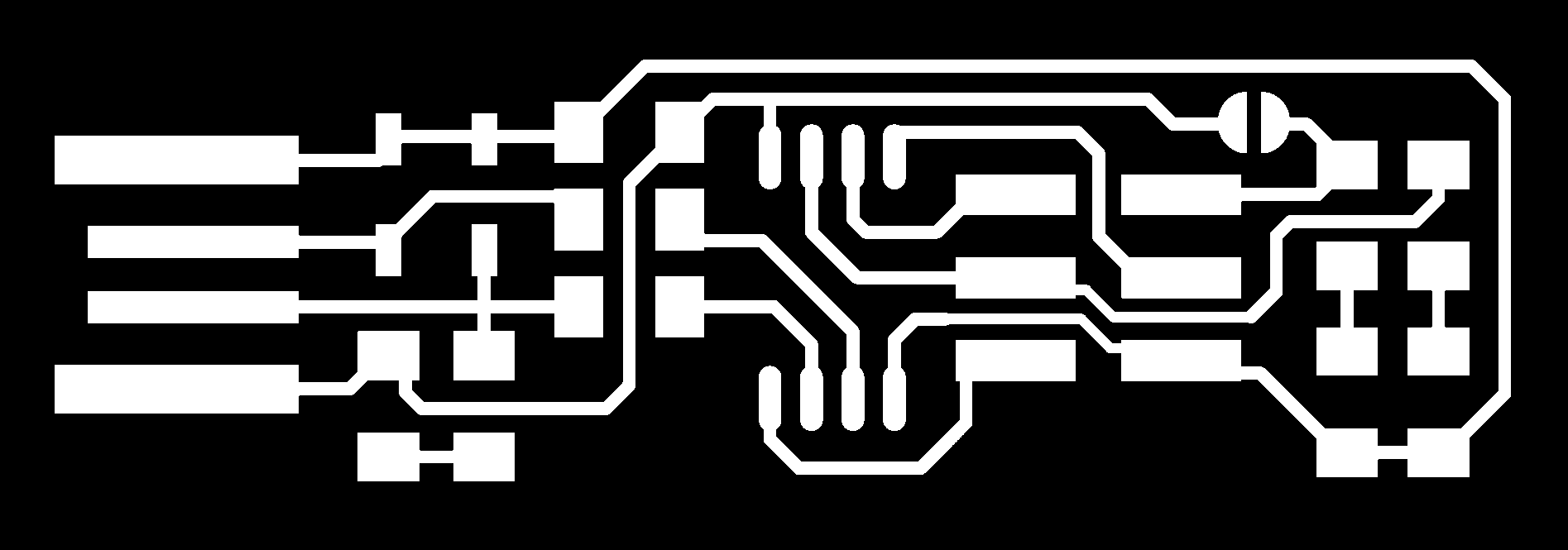
The fab module converts the .png image we give into a series of tool paths, these tool paths are defined by their coordinates. The .png image is a black and white layout of the board, and the black portions will be milled and the white portion is where the copper will be left.
Innorder to complete the PCB manufacturing process we have to do 2 process
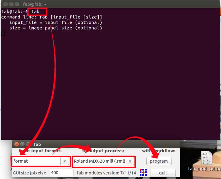
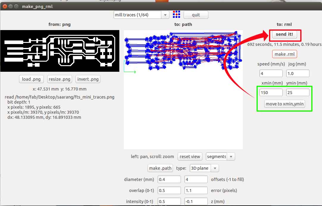
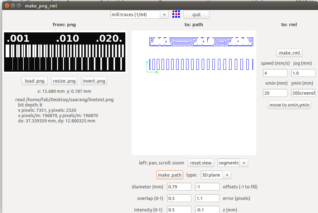
Got to the terminal and run fab Now the fab module will open and the select the input format to .png and select the output you want depending on your machine (modlella MDX 20).
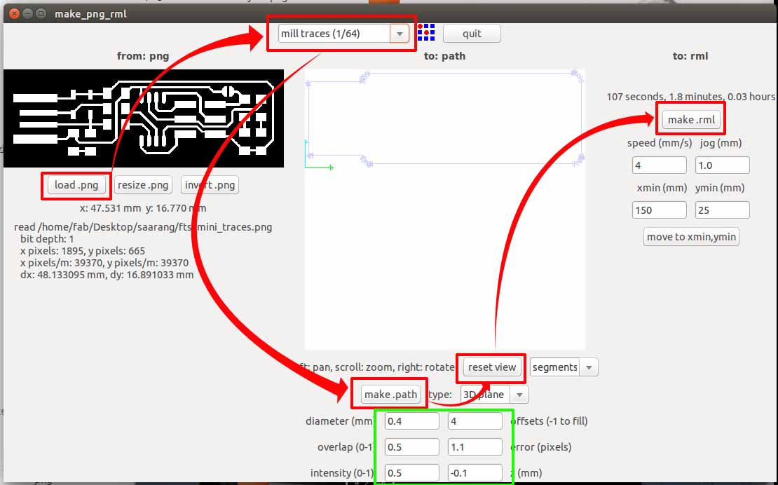
On the top menu select the process you want to use. For milling traces, select the milltraces(1/64) option. Now click load .png to load your traces file and click make path Now you can see the path the tool is going to move through. You can change the setting, I'm leaving it in the defaults. Now if you click make.rml and click send rml
1st we were suppose to prepare the sacrifical layer.But we already had a sacrifical layer .So I decided to go with it.
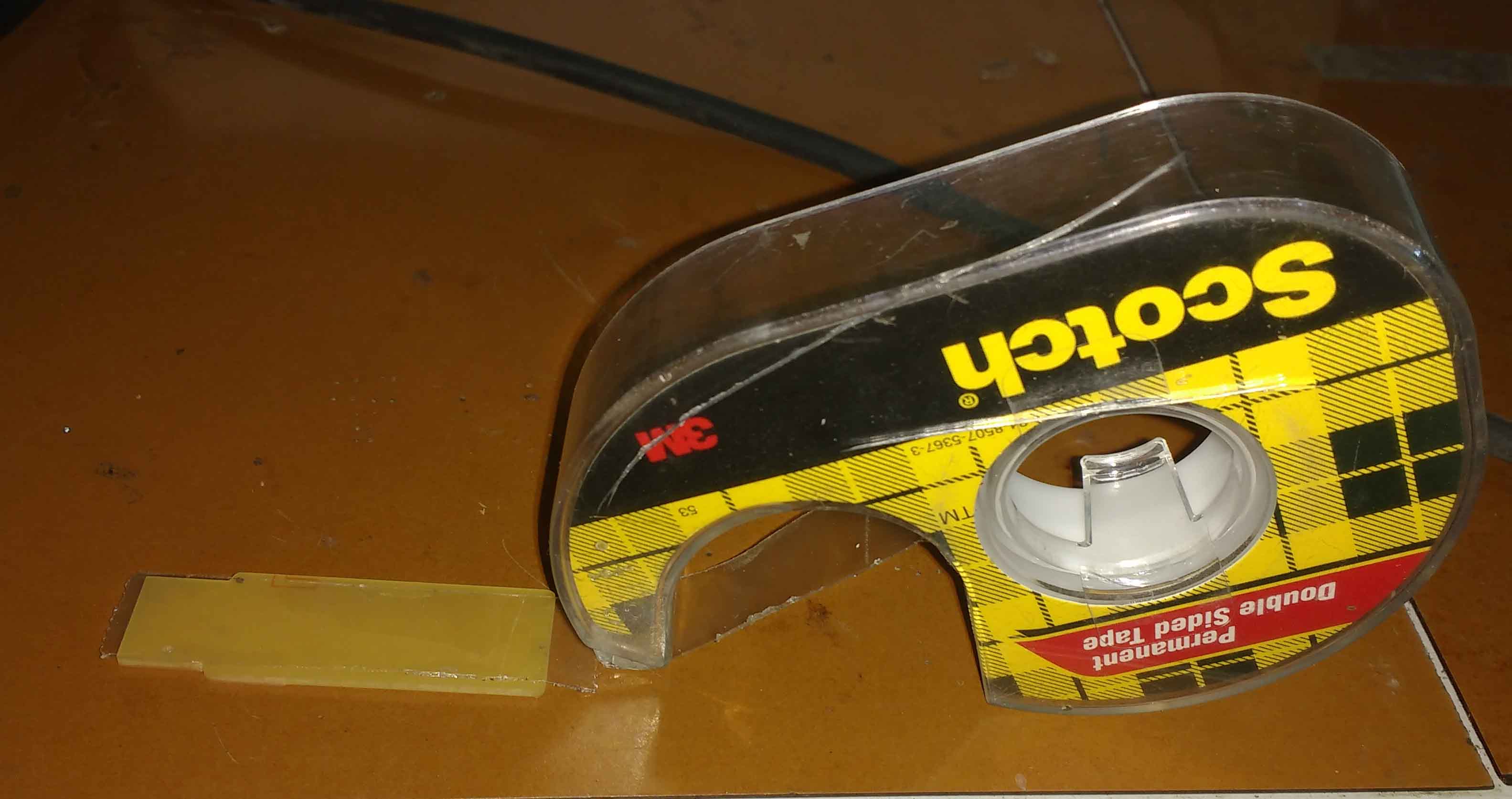
Next clean the PCB and Fix it to the CNC sacrifical layer with a double side tapes.Please make sure that the whole milling portion of the pcb is fixed to the table with the tape .If not the pcb may miss aline and may damage the cutting bit or the pcb itself.
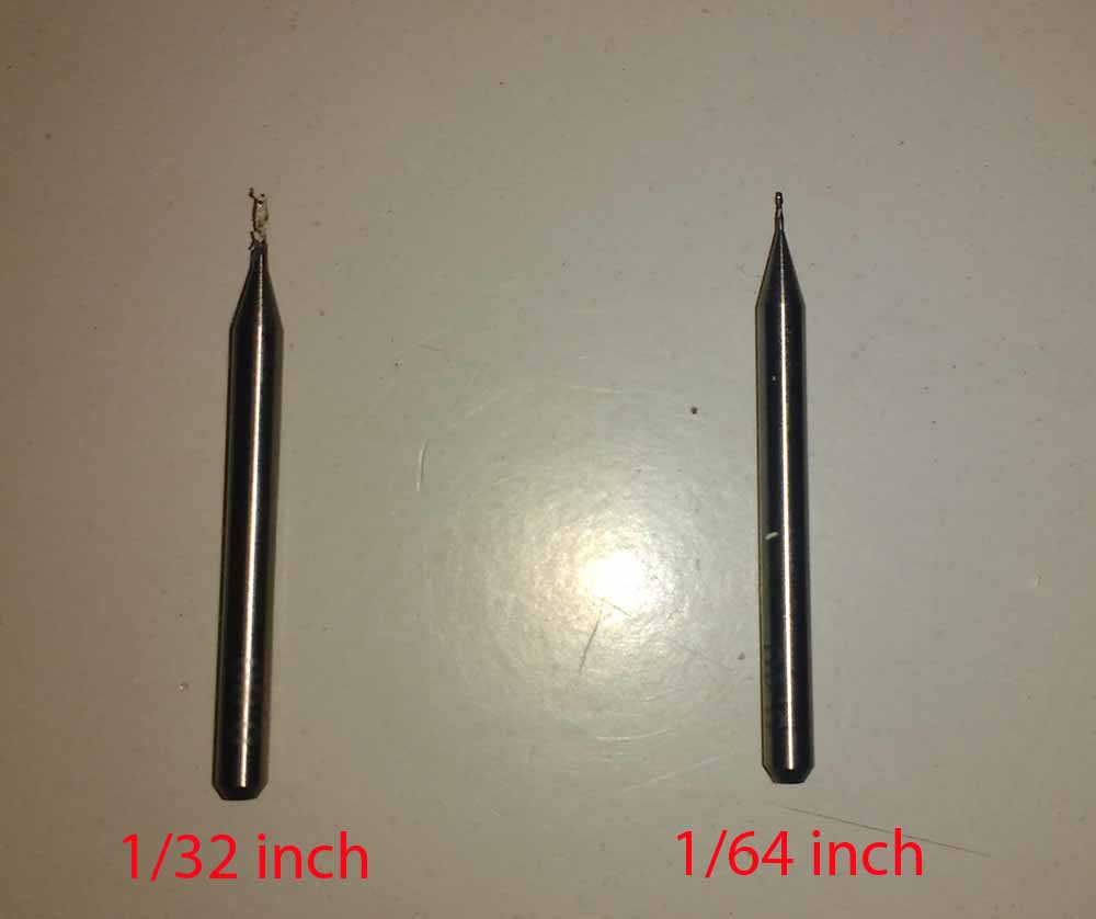
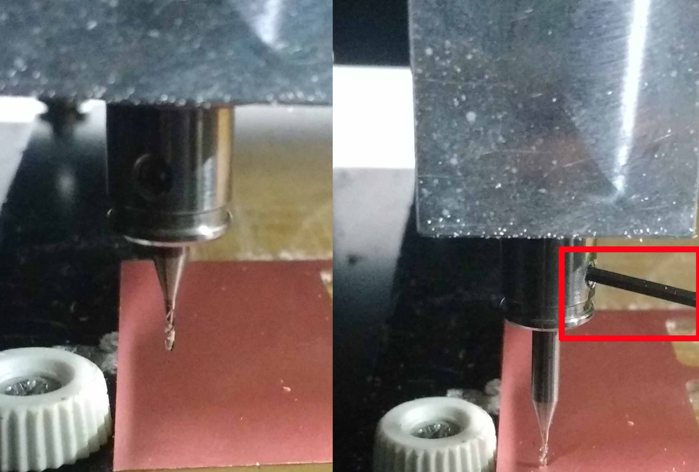
The 1/64 inch is used for tracing and 1/32 inch bit is used for cutting
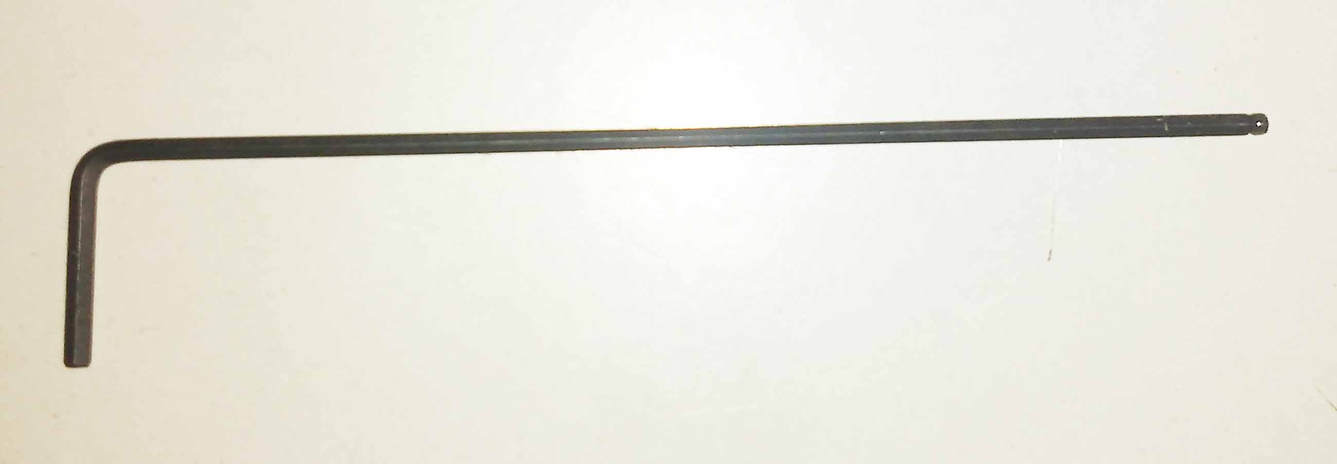
An L-key is used for releasing the bit from the chuck
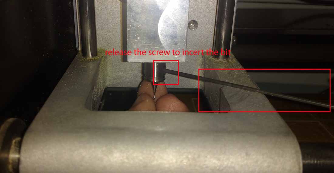
To set the Z-value correctly , we can use multiple ways but the most efficient and easiest way i found is
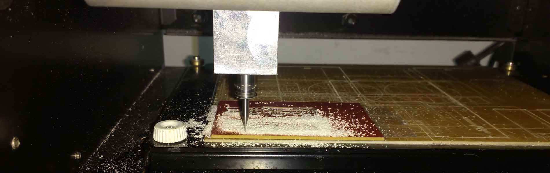
Complete the tracing process by sending it in to the milling Machine
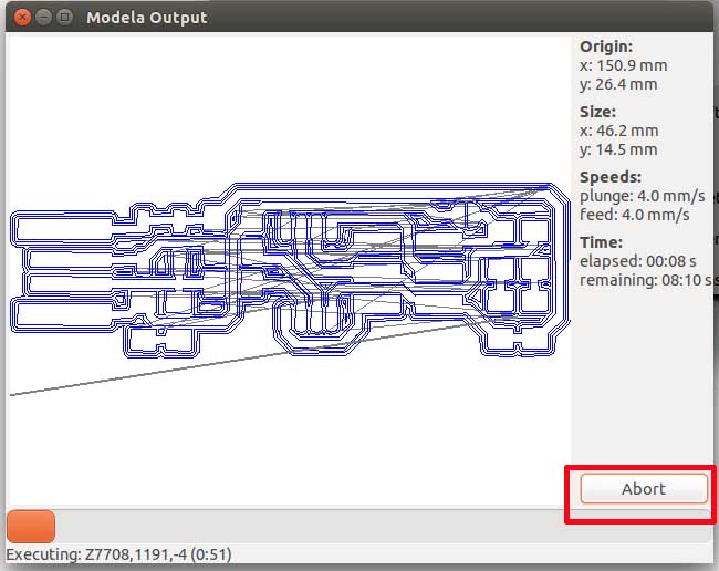
Incase we need to stope the process permanently we can use the abort button. If we wanted to stop the process for temporally we can use the view button on the modella.
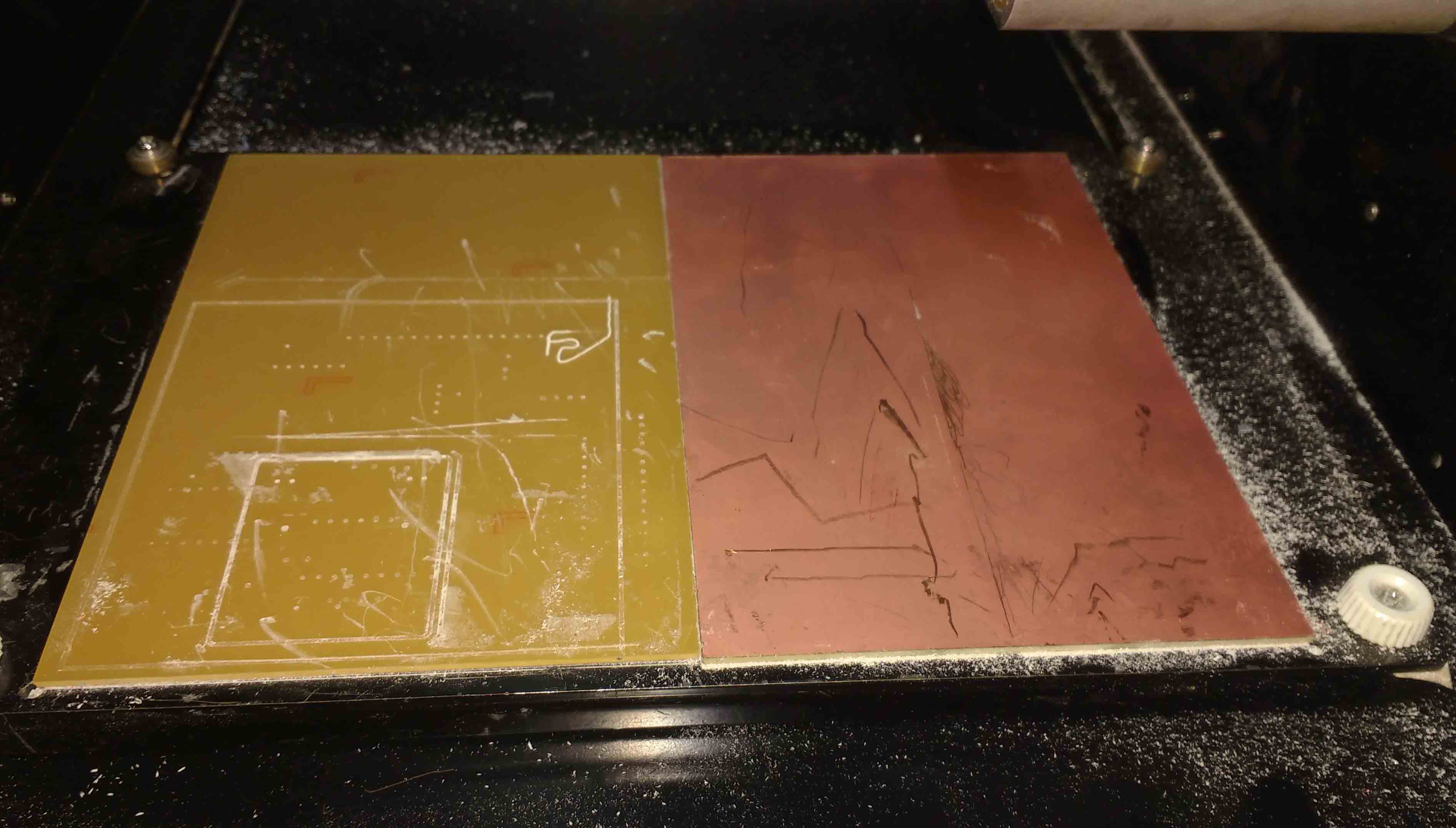
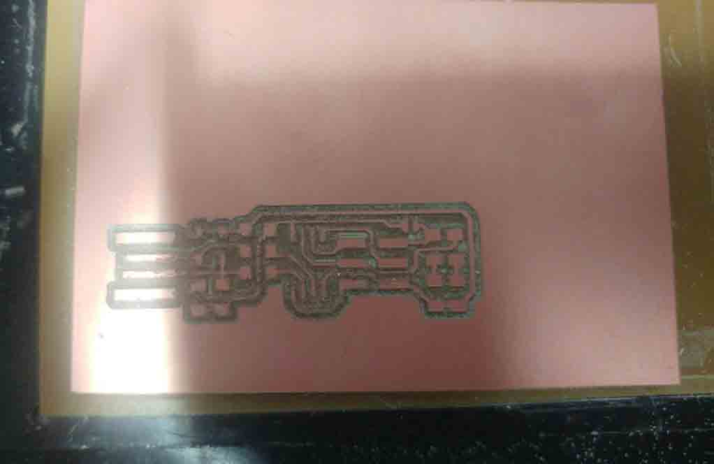
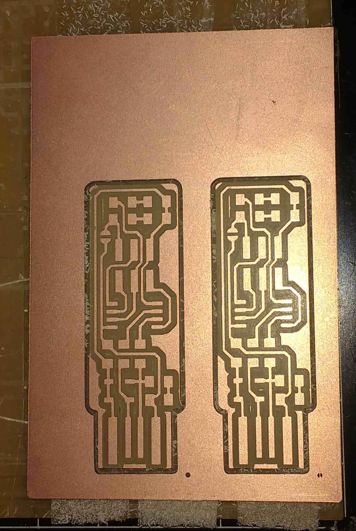
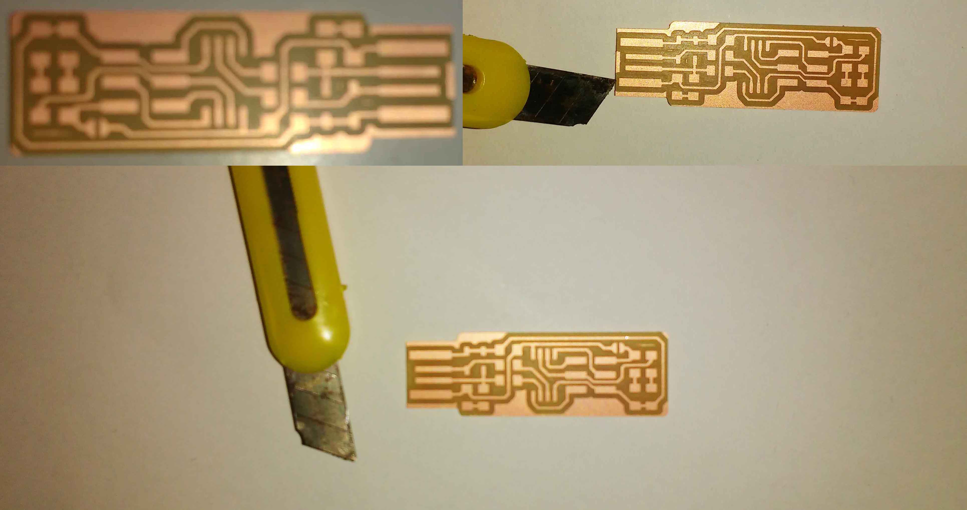
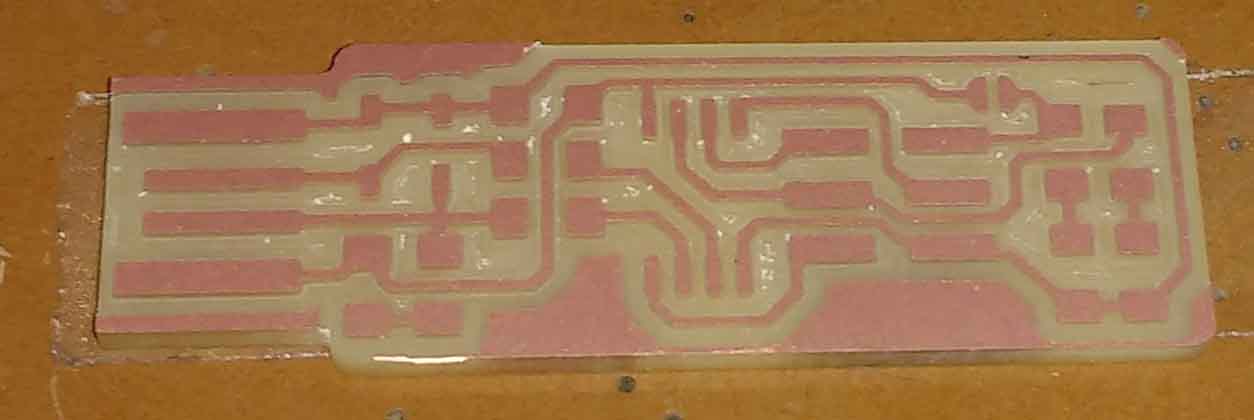
This is the PCB after completing traceing.
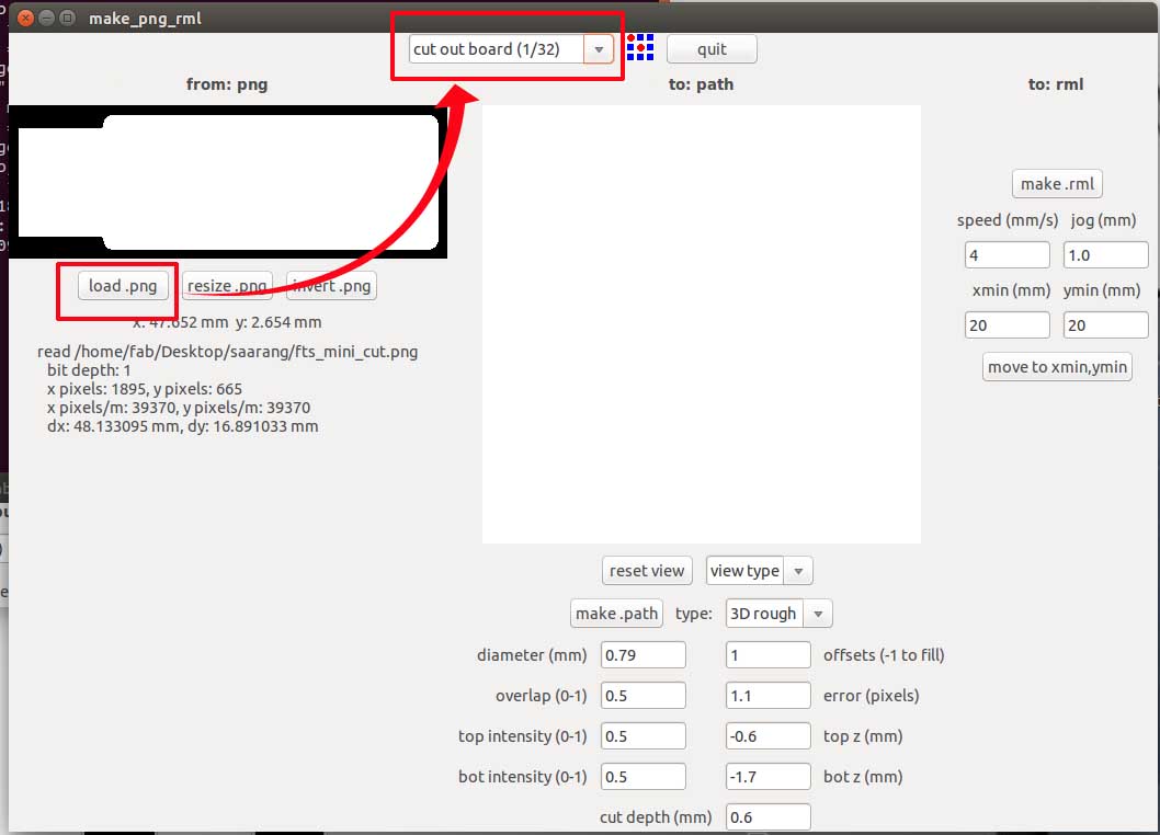
Load the cut file and change the bit to 1/32 . make the path and proced with milling after making the rml. Always be sure about not making a change in the origin.
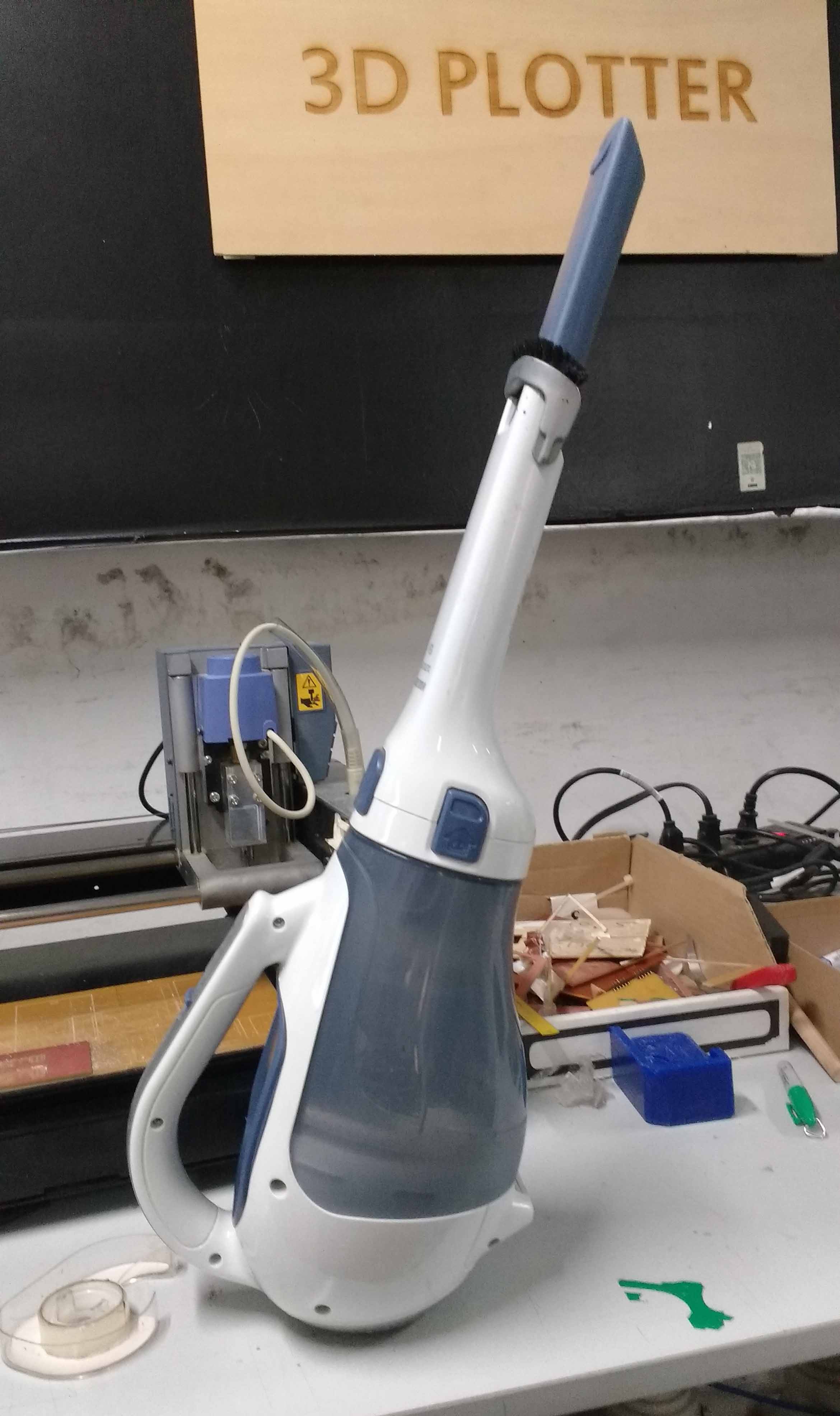
Clean the bed and the board with a vacuum cleaner after completing the millinging.
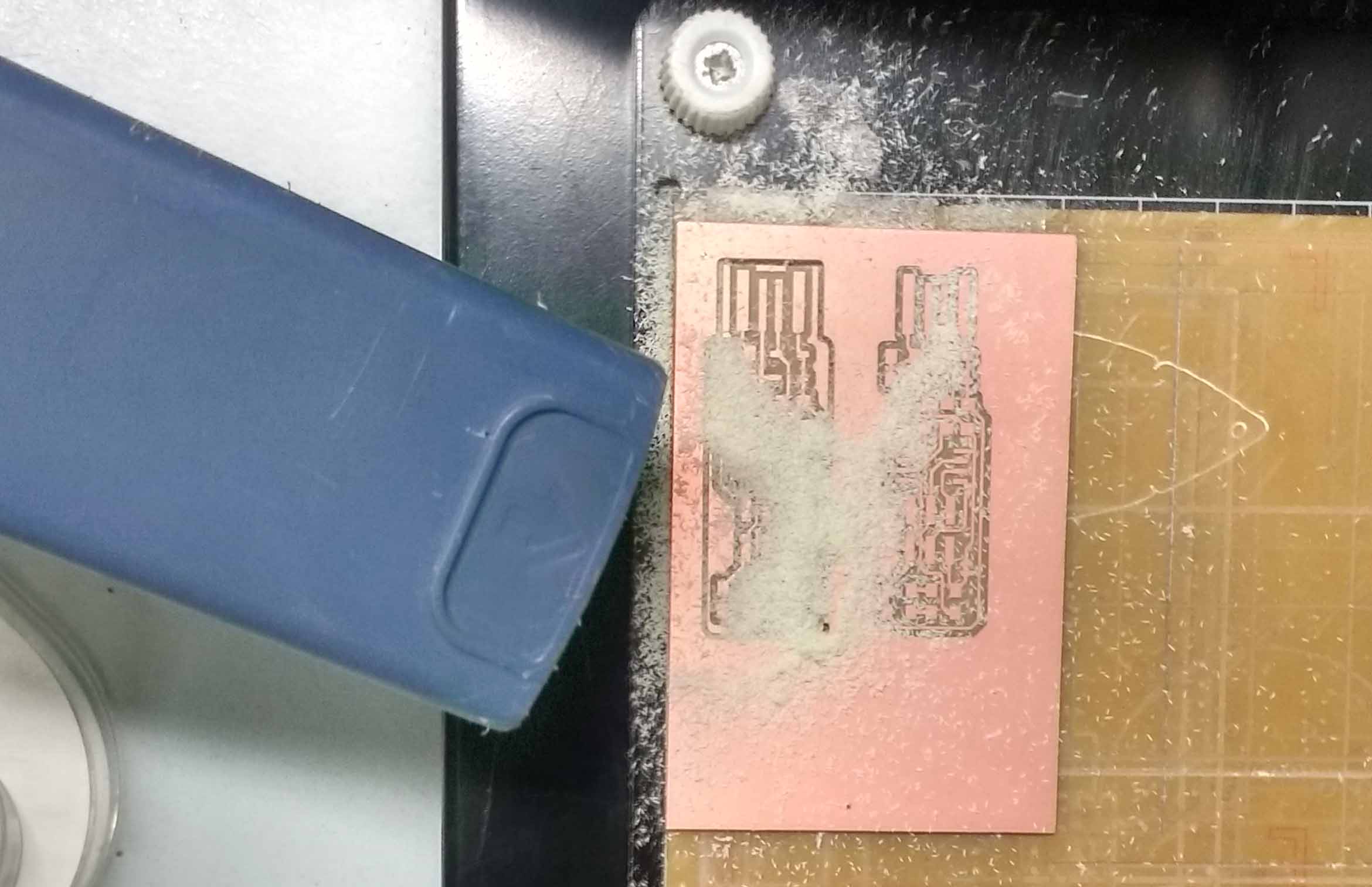
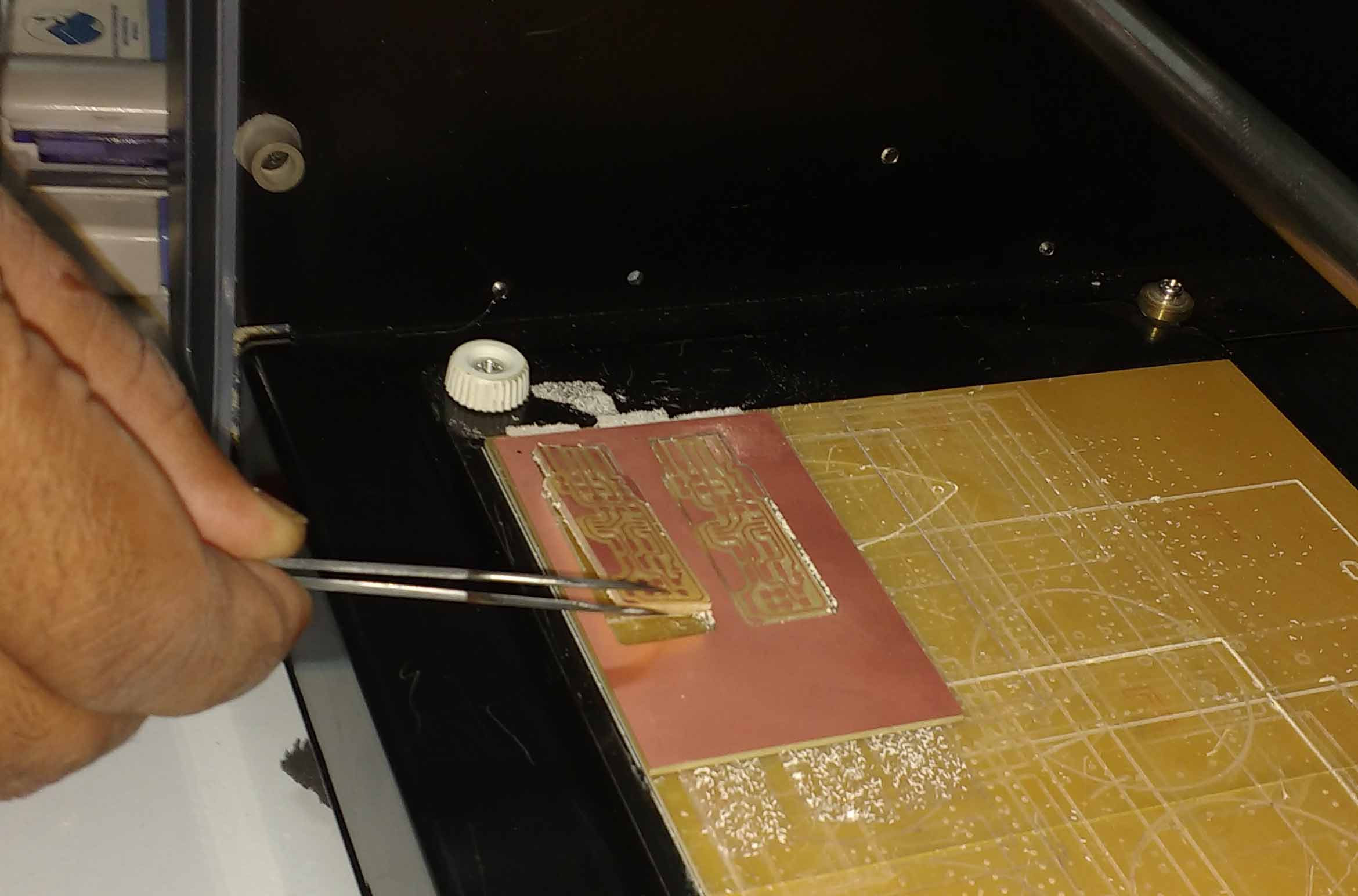
Remove the PCD carefully from the bed with a Tweezer or with the edge of a steel ruler.
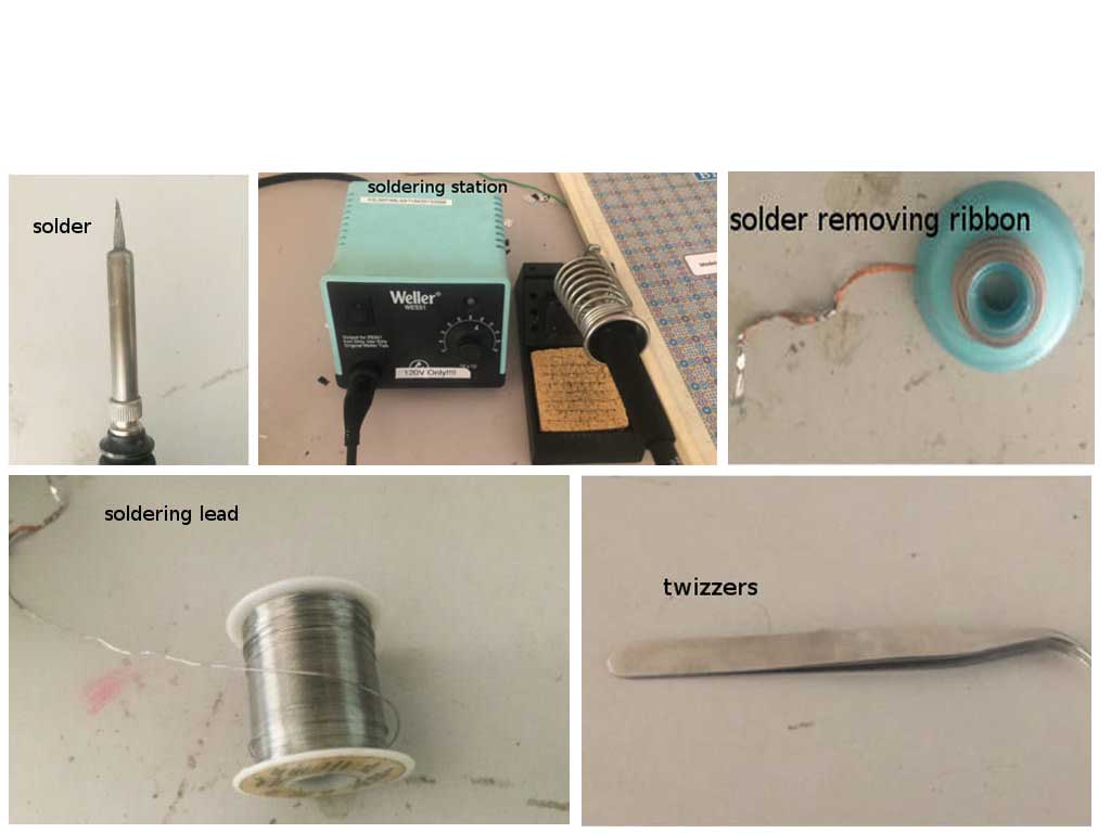
I have some previous experiences with through hole soldering .So I hope it won't be much harder for me to completing my soldering. Before we start soldering make sure all the required instruments are available in our desk
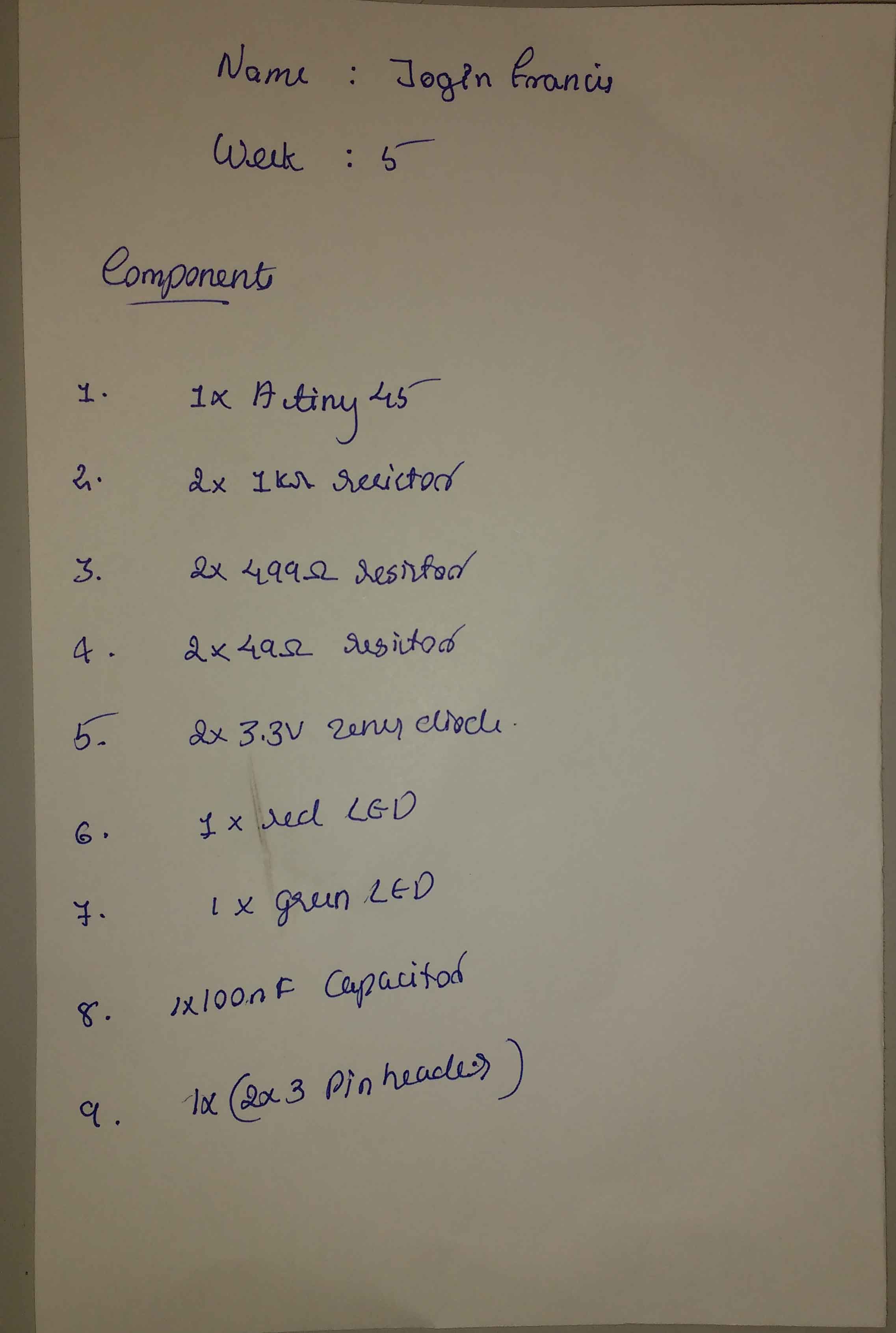
Make a list of all the reqired electronics components in a sheet of papper.
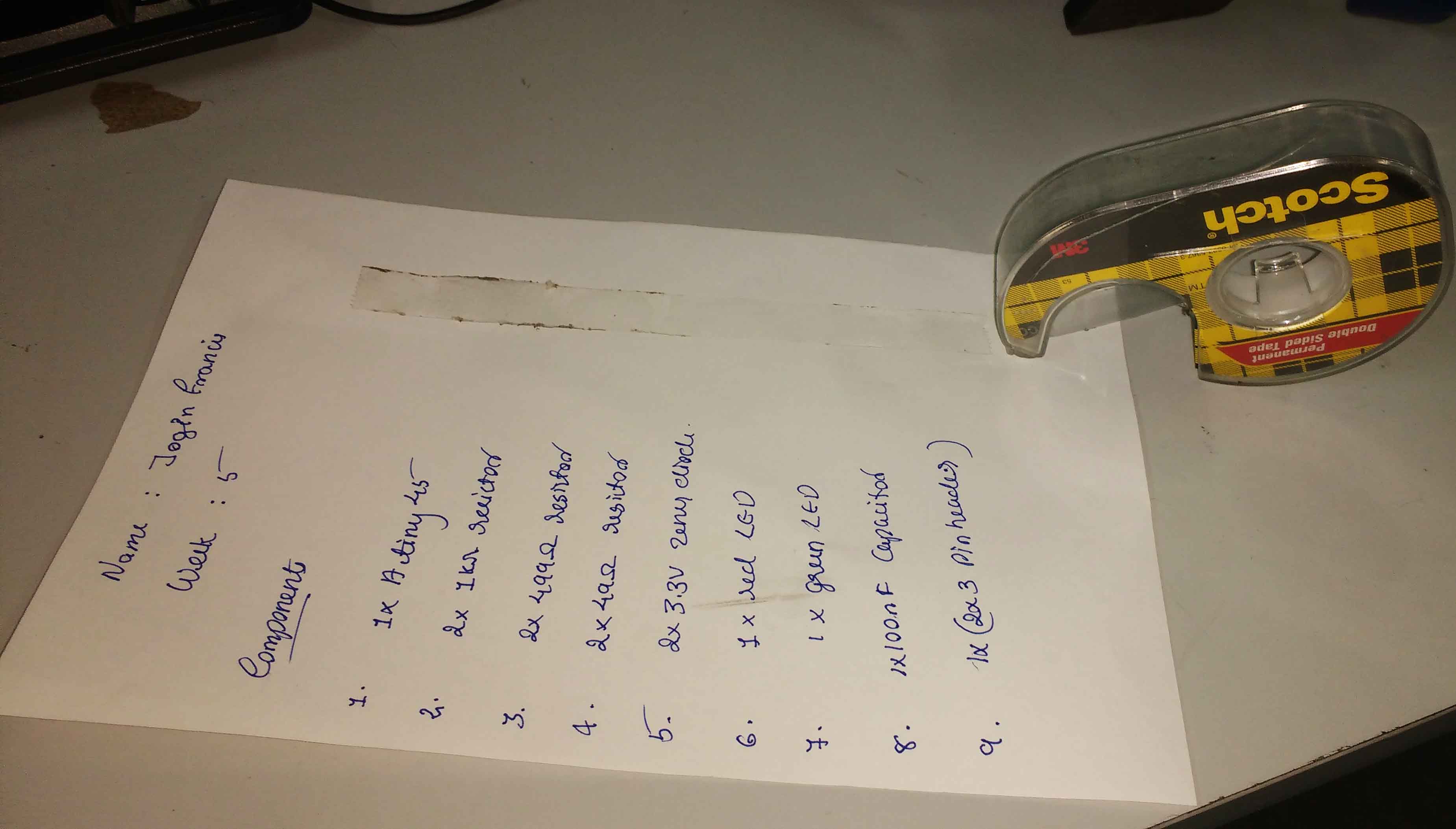
Stick a long piece of double side tape onthe rigth side of the component list .
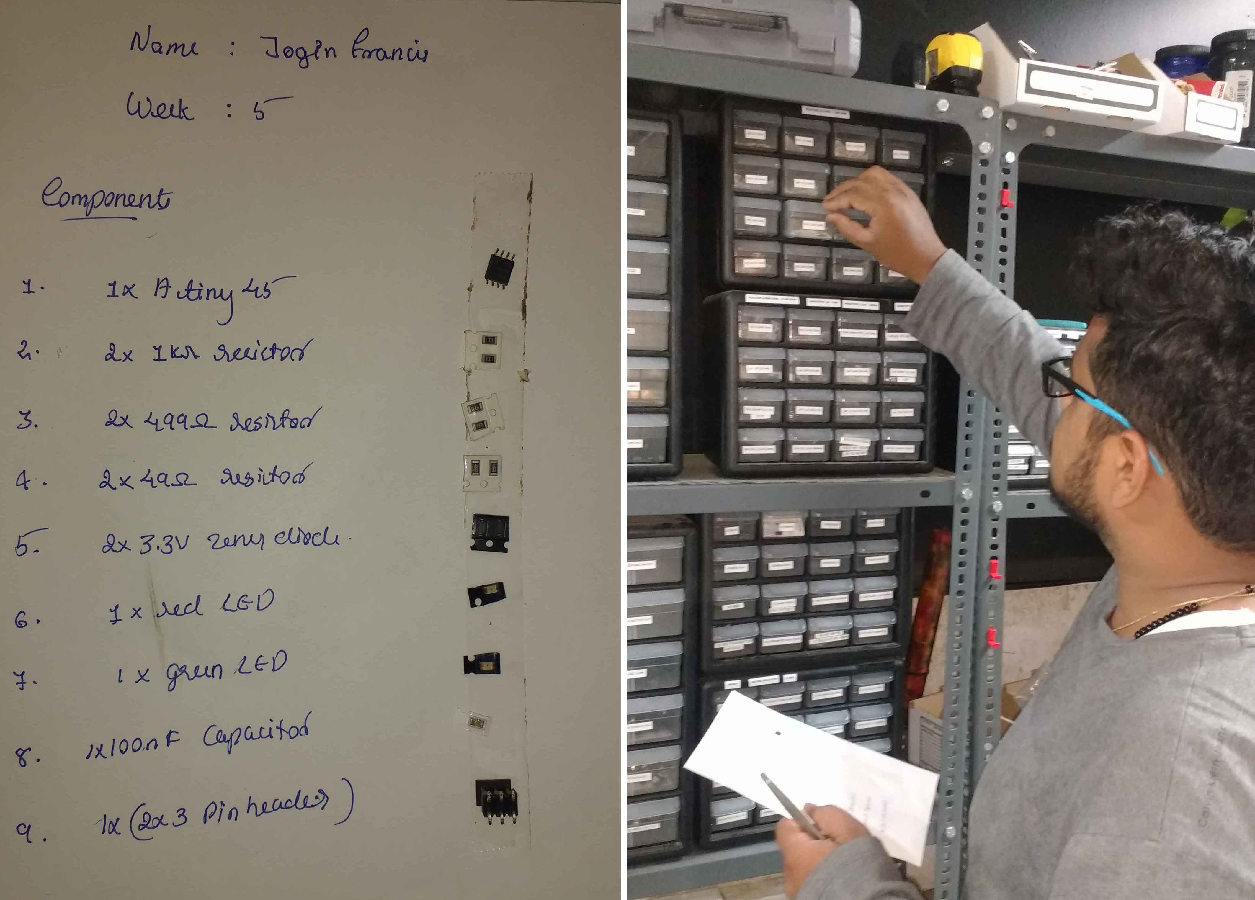
We can use the double side tape to stick components that we took from the inventory .The tape will keep the components in place and it will reduce a lot of confusions in future.
Remove all unwanted residues generated during milling.
For the easynes of soldering i sticked the PCB to the table with a piece of double side tape.
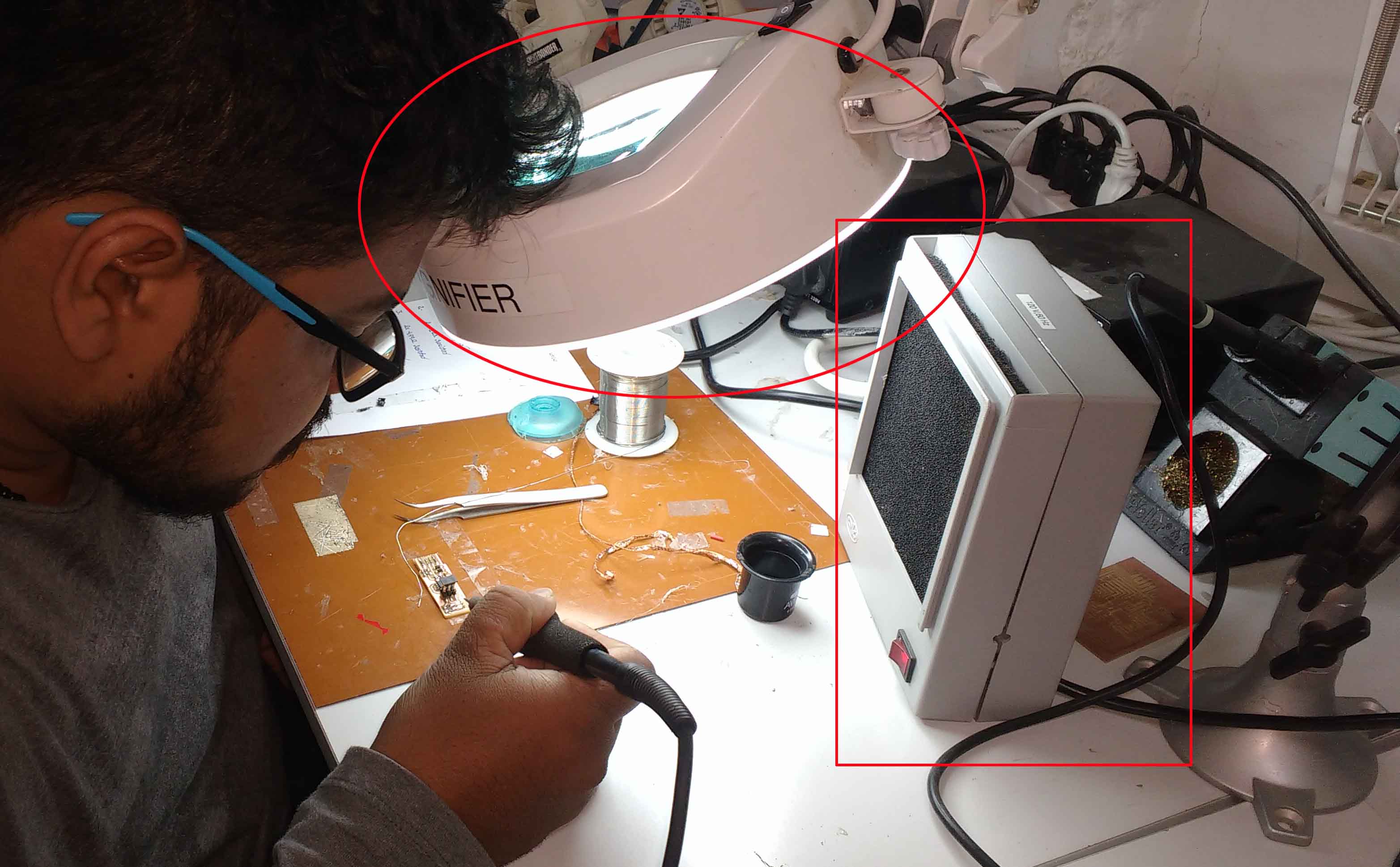
Make sure the enviournment has sufficient lighting and ventilation .Using the magnifying glass could probabily reduce the strain on our eyes.I always prefer to use them
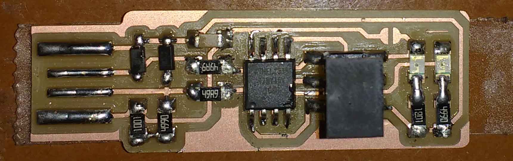
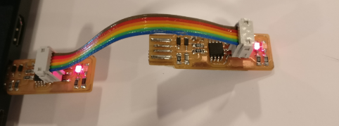
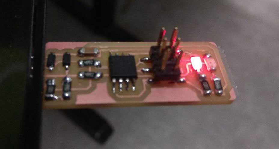
This is my finished USBtinyISP.
Once you finish soldering the components, It is time to test the connections and program the board. Look carefully at the board to see if all the connections are proper
If any components are loose or misplaced, de-solder them and put them in their correct places.If everything checks out, proceed to plug it into the USB port of your PC. If the red LED lights up everything is fine else repeat the about tests.The next step is programming the chip with the right firmware.
The make file of the firmware assumes that you are going to use a programmer in the usbtiny category (another fab ISP). If you're using a different programmer, first figure out what avrdude (the programming software) calls it.
Edit the file called Makefile. It is important to use a text editor intended for programmers. Near the top of the file, find the line that says:
PROGRAMMER ?= usbtiny
change usbtiny to whatever programmer you're using.
Plug the board into a USB port. USB2.0 is preferred over 3.0 if you have one, and use an extension cable so that you do not put strain on your board especially if your port is upside down. If you installed the red LED, it should be lit up now. If not, check the solder jumper and make sure that it is bridged. If your computer complains about a USB device drawing too much power, unplug the board and check for shorts.
Connect the programmer to the ISP header on your board. Note that there are two different orientations in which you can connect the cable; it is imporatant that you get pin 1 in the right place. Pin 1 is the MISO pin and it should be connected to the MISO pin of the board you are programming.
Type
In terminal and ensure the device is identified
After in the terminal run the command ‘make flash’. This will erase the target chip and program its flash memory with the contents of the .hex file you built before. You should see several progress bars while avrdude erases, programs, and verifies the chip.
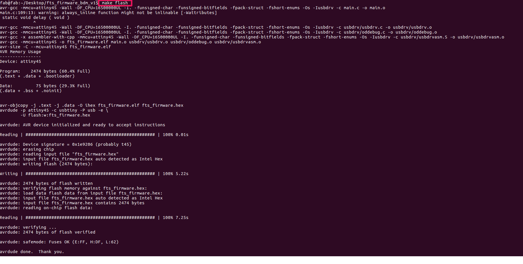
If something went wrong, check:
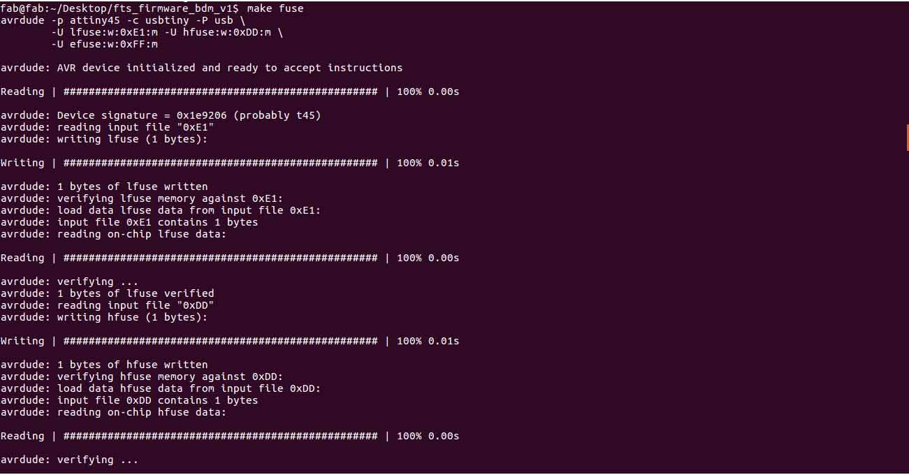
Detailed debugging steps are provided in the FabTinyISP documentation page. Once you've successfully programmed the flash memory, it's time to set the configuration fuses:Go to the terminal and run the make fuses command. This will set up all of the fuses except the one that disables the reset pin.
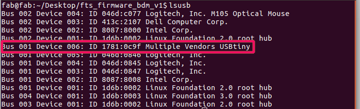
type
check wether the programmer is detected. If you see a "Multiple Vendors USBtiny" device, then the programming has worked. If it didn't, the dmesg command might provide more info on what went wrong.
Blow the Reset Fuse
We need to change the bit that will turn the ATtiny45's reset pin into a GPIO pin.This will disable our ability to reprogram this ATtiny45 in the future, hence make sure everything is working before doing this. Connect your ISP programmer to your board one more time, and in the Terminal run
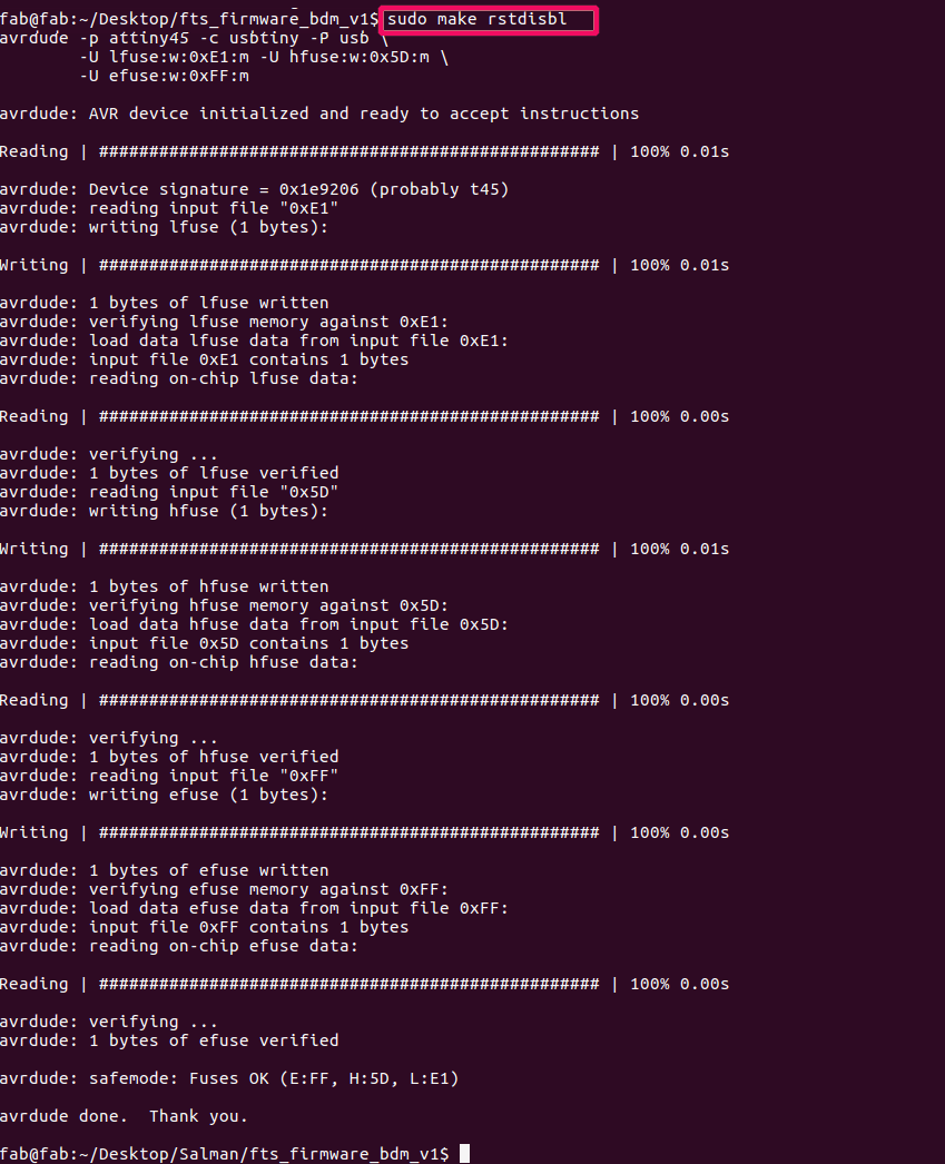
This does the same thing as the make fuses command.with that, avrdude will never be able to talk to this chip again through the ISP header. Now our programmer is finished.
Don't know why .. But i cauld able to complete all these with out any error.
For the group assignment we need characterize the specifications of our PCB production process.Since i exaplined about the production process during my assignment next one is to find-out the resolution of mill bits we are using.

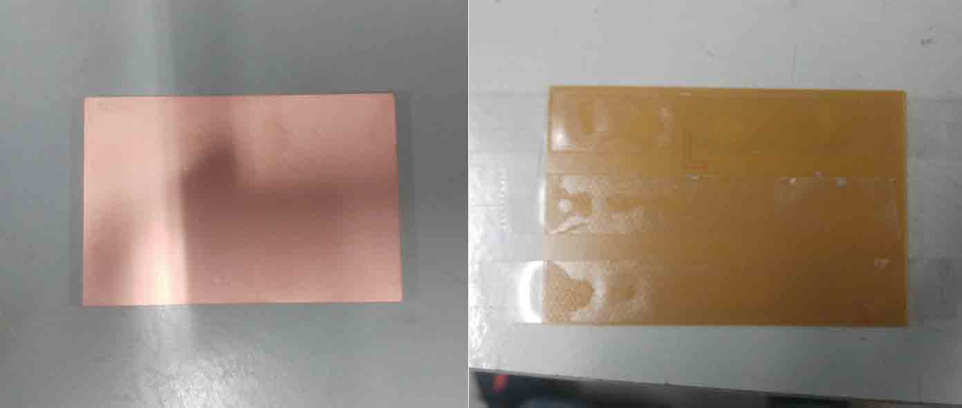
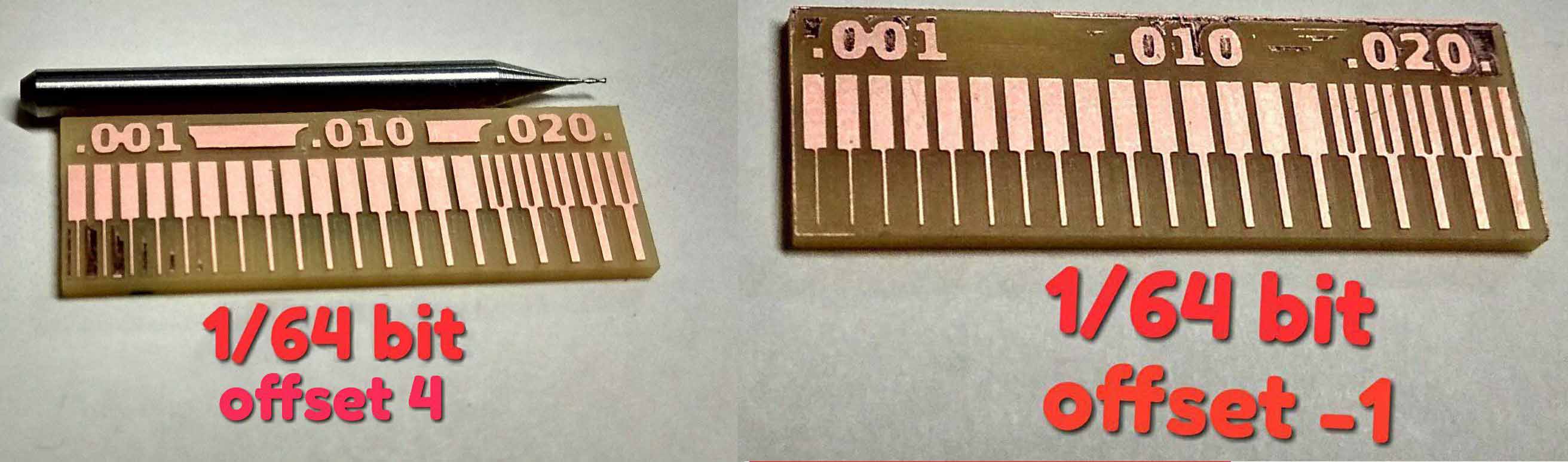
Initially we milled our test pad with 1/64 bit.We choose to mill one board with offset as 4 and another with offset -1.
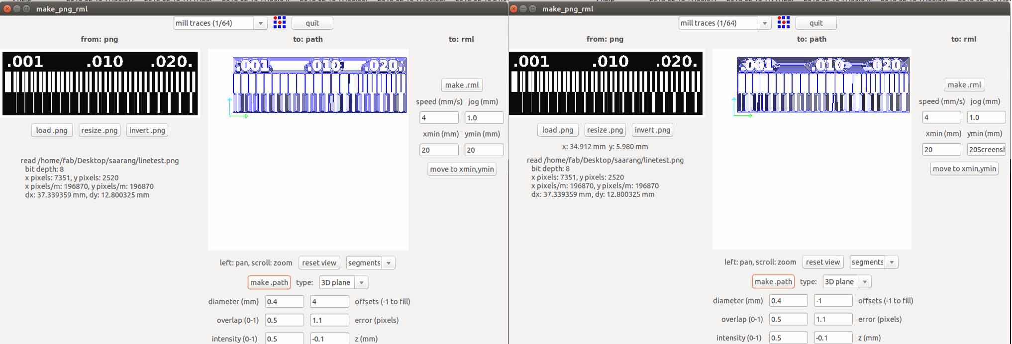
We can visually observe the difference. When we used offset 4 some of the copper is not removed properly and in the case of -1 it is almost removed completely.
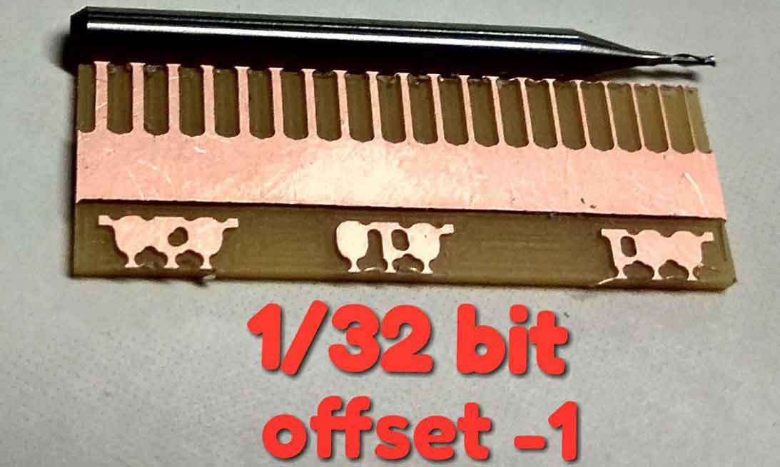
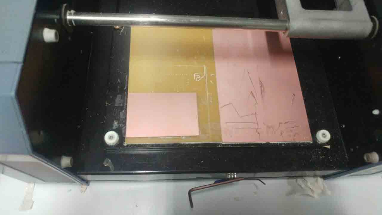
Next we tried the 1/32 bit .
This image clearly shows the difference in milling resolution of 1/32 and 1/64 bits.Usually we use the 1/64 bit for milling trace and 1/32 for cutting and drilling. So it is okey of drilling and cutting.