Assignment :
Group assignment: Test the design rules for your printer(s) (group project)
Design and 3D print an object (small, few cm) that could not be made subtractively
3D scan an object (and optionally print it)
I don't have any previous experience in 3D printing or 3D scanning. But i was looking for an opertunity to understand these new trends in manufacturing
3D printing refers to processes in which material is joined or solidified under computer control to create a three-dimensional object, with material being added together (such as liquid molecules or powder grains being fused together). 3D printing is used in both rapid prototyping and additive manufacturing (AM). Objects can be of almost any shape or geometry and typically are produced using digital model data from a 3D model or another electronic data source such as an Additive Manufacturing File (AMF) file (usually in sequential layers). There are many different technologies, like Stereolithography (STL) or Fused Deposit Modeling. Thus, unlike material removed from a stock in the conventional machining process, 3D printing or AM builds a three-dimensional object from computer-aided design (CAD) model or AMF file, usually by successively adding material layer by layer.(wiki)
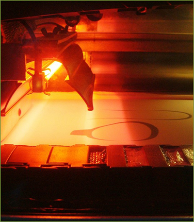
Vat polymerisation uses a vat of liquid photopolymer resin, out of which the model is constructed layer by layer. An ultraviolet (UV) light is used to cure or harden the resin where required, whilst a platform moves the object being made downwards after each new layer is cured.
Vat polymerisation uses a vat of liquid photopolymer resin, out of which the model is constructed layer by layer. An ultraviolet (UV) light is used to cure or harden the resin where required, whilst a platform moves the object being made downwards after each new layer is cured.
The binder jetting process uses two materials; a powder based material and a binder. The binder acts as an adhesive between powder layers. The binder is usually in liquid form and the build material in powder form. A print head moves horizontally along the x and y axes of the machine and deposits alternating layers of the build material and the binding material. After each layer, the object being printed is lowered on its build platform..
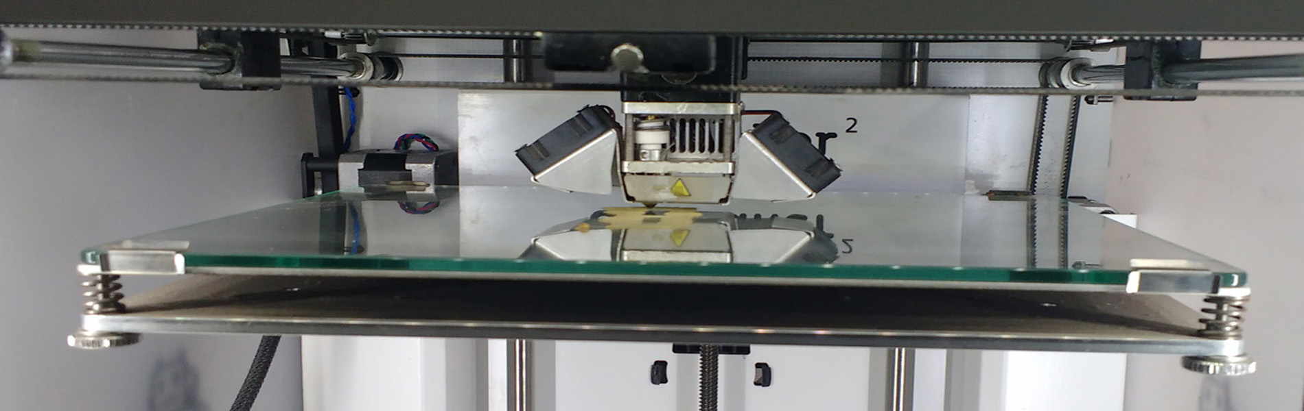
Fuse deposition modelling (FDM) is a common material extrusion process and is trademarked by the company Stratasys. Material is drawn through a nozzle, where it is heated and is then deposited layer by layer. The nozzle can move horizontally and a platform moves up and down vertically after each new layer is deposited. It is a commonly used technique used on many inexpensive, domestic and hobby 3D printers.
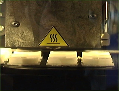
 Powder bed fusion (PBF) methods use either a laser or electron beam to melt and fuse material powder together. Electron beam melting (EBM), methods require a vacuum but can be used with metals and alloys in the creation of functional parts. All PBF processes involve the spreading of the powder material over previous layers. There are different mechanisms to enable this, including a roller or a blade. A hopper or a reservoir below of aside the bed provides fresh material supply. Direct metal laser sintering (DMLS) is the same as SLS, but with the use of metals and not plastics. The process sinters the powder, layer by layer. Selective Heat Sintering differs from other processes by way of using a heated thermal print head to fuse powder material together. As before, layers are added with a roller in between fusion of layers. A platform lowers the model accordingly.
 Directed Energy Deposition (DED) covers a range of terminology: ‘Laser engineered net shaping, directed light fabrication, direct metal deposition, 3D laser cladding’ It is a more complex printing process commonly used to repair or add additional material to existing components
I have chosen autodesk fusion 360 for doing my design. i have some previous experiences in designing in fusion the steeps i have done.
.jpg)
Cura is an easy to use slicing and g code generator.It was created by David Braam; he was later employed by Ultimaker to maintain the software
.jpg)
Open file in cura
.jpg)
Select support material and bed adhesion type
.jpg)
You can go through the layers and different types of views.you can check wether there is any overhang or any internal structural problems.Then upload the file to the SD card
Insert the SD card in the slot
.jpg)
.jpg)
Remark! Since i forgot to enable the support material in cure.The structure loose its diamentional constrains and now it seems like a melted wax bolck.
I found that our ultimaker version uses the same material for suppot as well as for building .So it will be difficuls for me to clear and also for seperating my double headed nut and bolt structure.
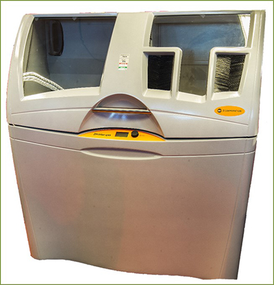
So i desided to choose the "dimension sst 1200es" printer in our lab for printing. Because it uses 2 different materials for printing and support so it will be easier for me to remove the support materials
.jpg)
.jpg)
"Dimension sst 1200es" is an industrial grade 3D printer with excellent adhesion between layers and very good build quality. it support dual extruder so that we can print build material of one type and support material with a different chemial property .
.jpg)
Check wether your device is turned on and ready to receive files
.jpg)
.jpg)
Open file
.jpg)
Correct the orientation
.jpg)
Selet the type of material support material,number of copies,units etc.Since I am printing a small model and it need to be strong I choose "Sparse - high density" As moedel interior ,0.0100 as layer resolution and "SMART" support.
.jpg)
Check wether the device is ready to receive file. If it is in idle proced with printing else correct your problem
.jpg)
.jpg)
If everything is perfect the machine ask to start model
.jpg)
Press the start model button in the printer to start printing
.jpg)
.jpg)
.jpg)
This is the printer output.
Carefully remove the build plate from the machine . To remove the plate slightly pull the handle of the build plate .This will release the lock of the plate .Now we can easly separate the plate From the machine .Again we need to put it in the support cleaning apparatus for cleaning the support material
Place the material in a metal cage inside the reaction chamber. set the temperature to 85 degree celsius . Since I needed to remove support from inside the treads I decided to set the time for 5 hours .
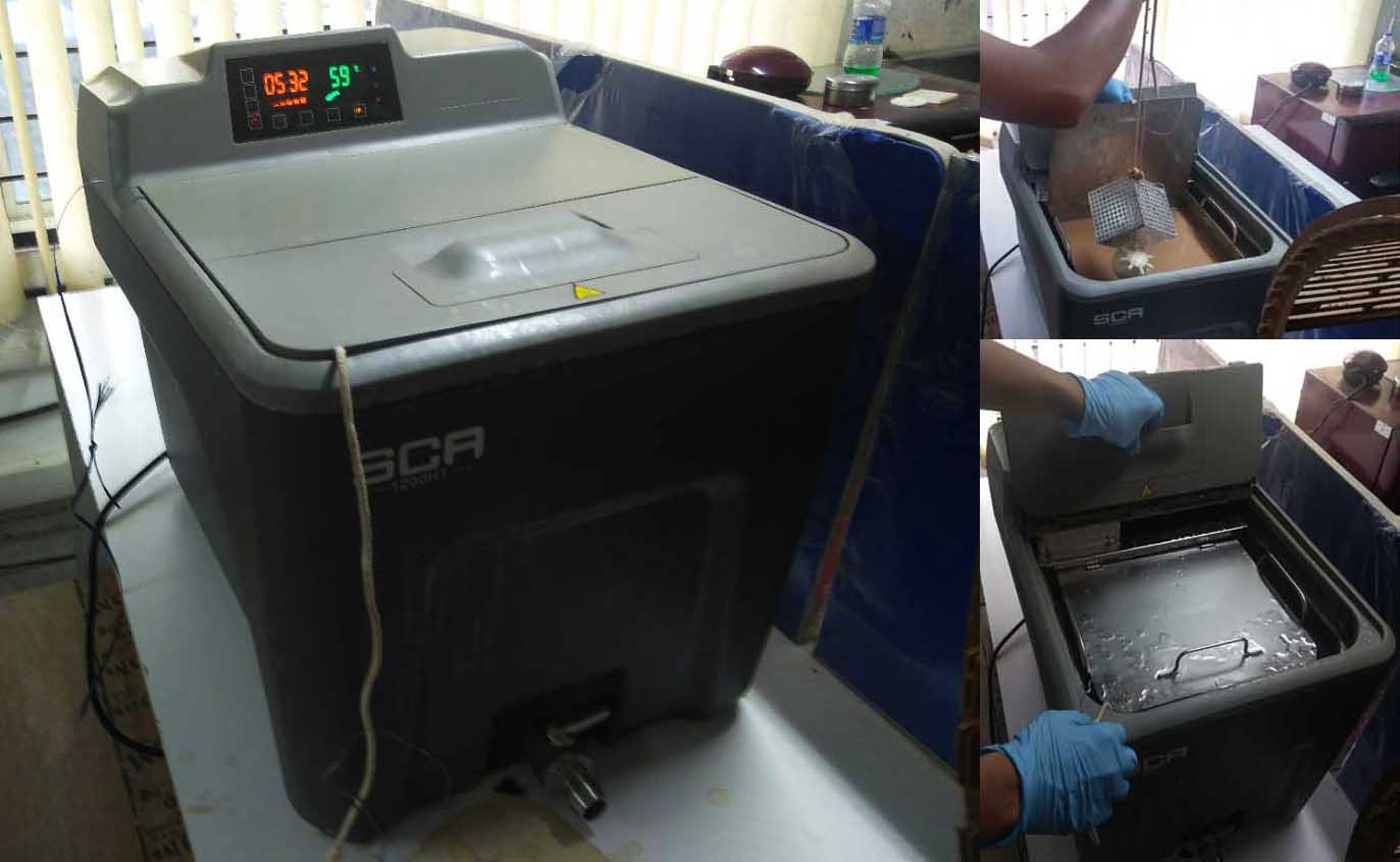
Always wear gloves in handling with heat and chemicals.
Take the model from the device and clean it with running water.
.jpg)
This is the final output
.jpg)
With the initial help of a spanner now the nut and bolt can rotate independently.
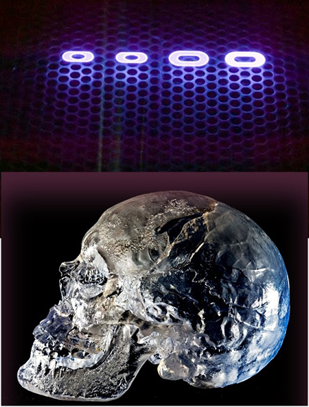
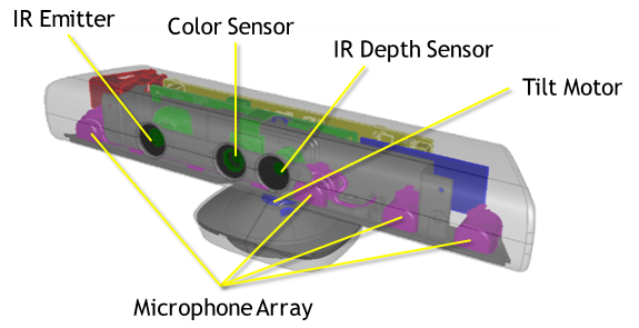
Kinect is Microsoft’s motion sensor add-on for the Xbox 360 gaming console. The device provides a natural user interface (NUI) that allows users to interact intuitively and without any intermediary device, such as a controller.
The Kinect system identifies individual players through face recognition and voice recognition. A depth camera, which “sees” in 3-D, creates a skeleton image of a player and a motion sensor detects their movements. Speech recognition software allows the system to understand spoken commands and gesture recognition enables the tracking of player movements. Although Kinect was developed for playing games, the technology has been applied to real-world applications as diverse as digital signage, virtual shopping, education, telehealth service delivery ,Robotics ,3D mapping etc
.jpg)
There's a trio of hardware innovations working together within the Kinect sensor:
For this week I used kinect for creating a 3D model of a handheld vacuum cleaner in our lab.
I placed the vaccum cleaner ina roll of masking tape . This raised the model from the supporting table and there by It will be easier for removing the backgroung later.Also the roll helped tho rotate the model easly.
.jpg)
I used KScan 3D Software to scan the object.
.jpg)
I used 20 successive images to complete the scanning
After completing the scanning click the align button to align all scans in the corresponding places
After completing the align press the combile button this will combile all the individual scans in to a single model
.jpg)
Press the finalize button to complete the whole process.This is the final model generated.
.jpg)
The model we obtained during the last process is a 3D mesh geometry .Since we didn't scanned the bottom area there is a hollow section under the model .We need to clear the void and need to convert it in to a solid model.
I used an online tool called vectary to edit the mesh geometry.It is very easy to use and don't need to download anything.
.jpg)
just open the platform and import our model to the enviournment.
.jpg)
Select the mesh tool -> weld and select the gap to be filled.
.jpg)
It will automatically fill the gap and will create a complete model.
.jpg)
Export the model as stl to the local system.I used ultimaker to print my scaled down model.I used Infill 50% ,layer height 0.1 mm and 0.1 print speed .I enabled support and Build Plate Adhesion.
.jpg)
Our group assignment was to test the design rules of our printer. We used a design from Thingiverse.The following are the design specifications of this particular test file.
We Printed with twice with different parameter.
.jpg)
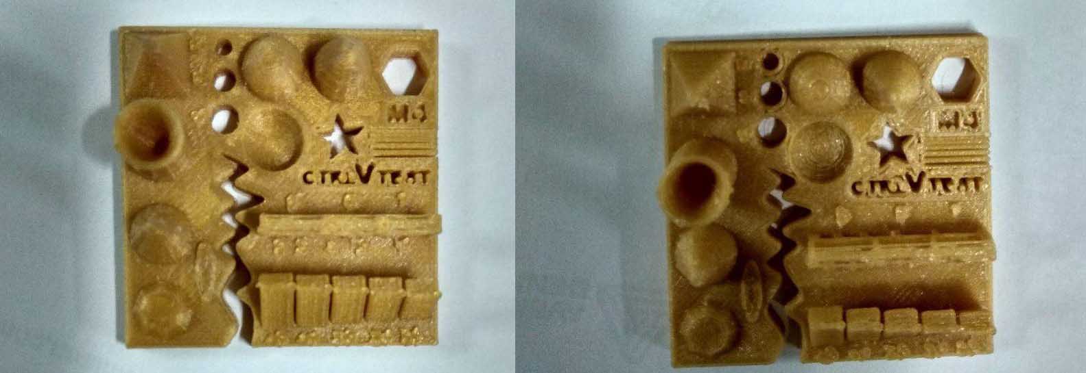
The first print came out quite good. The only problem that I felt was with the bridge print in which the top three members (7,8 and9mm) collapsed and the extra brim at the curving slot which was unnecessary. So the maximum bridge length that we can print without support in roughly 6mm in this settings. There was also an interface between the walls at .1 and .2 mm. So the minimum thickness that we can safely use is .3mm.
For the second the surface finish for this one didn't come out as good as the previous one but still, it was a decent looking piece. The problem with the bridges and walls persisted and the brims inside the slots were completely removed.