Assignment :
Make something big (on a CNC machine).
This is realy interesting.This is the first time i got an opertunity to use ShopBot CNC machine . From my school days onwards i used to work with woodworking tools so i realy know the paine of making something in the correct dimension .Sometimes the joints maynot be tight or may be the whole structure willbe in out of alignment .So from that that ages onwards i was looking for something for precision .It was an year befor my college that me and my brother desided to create a CNC of ourown.
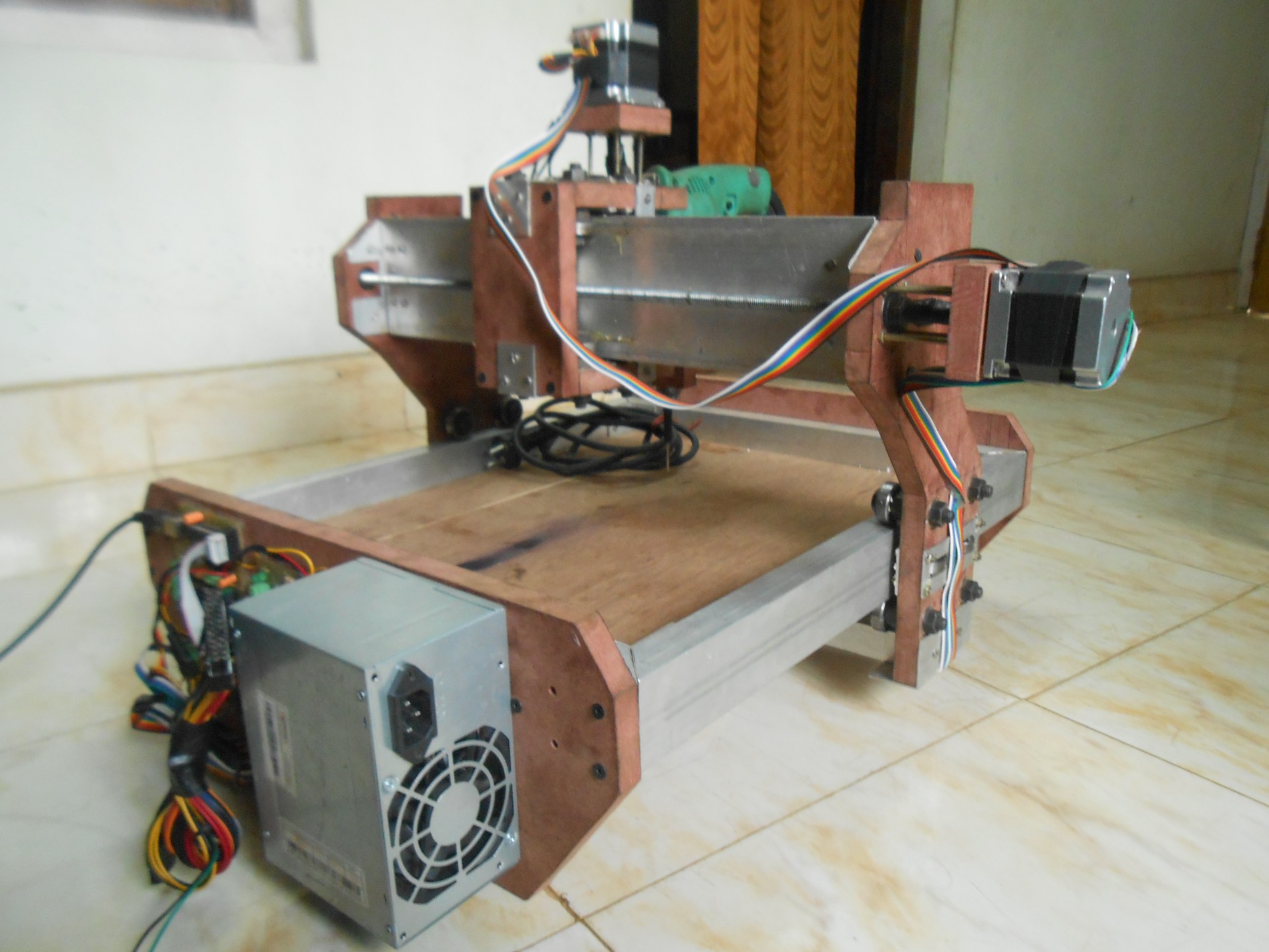
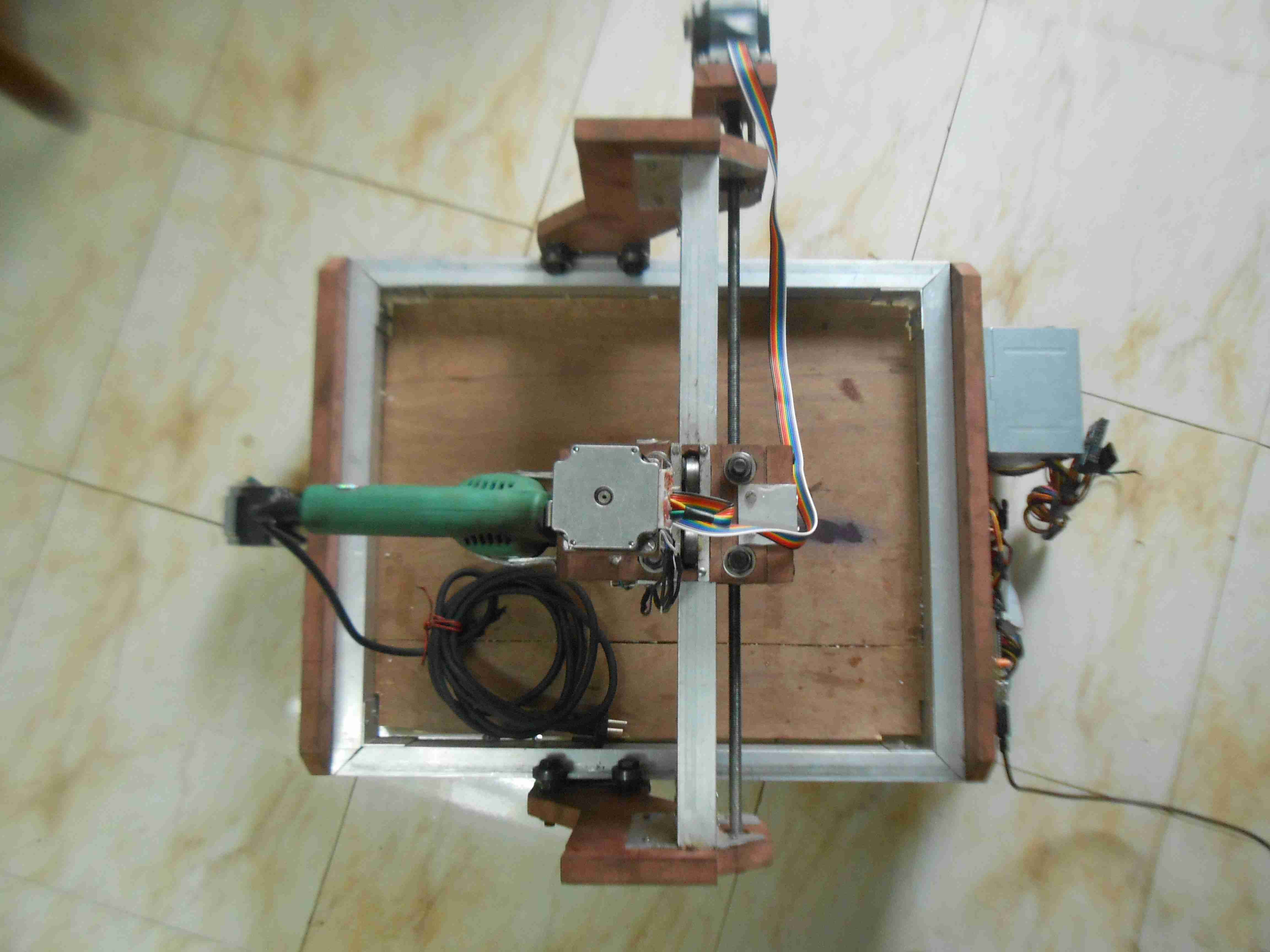
Our intial attempt was based on some locally available materials .Though it worked with some perfection .we couldn't able to attaine a precision below 1 to 2 millimeters. also we couldn't able to find a proper end effector . At that time the cost of a router was more than the money we required for our CNC structure to build. So we used a hand driller for that.So today we can try the ShopBot .
Initially lets brief about what is a CNC :A CNC is a Computer numerical control automation of machine tools by means of computers executing pre-programmed sequences of machine control commands. [wiki]
The process involves creating a CAD(Computer Aided Design) file of the desired object. Then a specialized CAM (computer aided Manufacturing) software is required to convert the 3D CAD file into a set of codes which the machines can understand. CNC machining language, called G-code essentially controls all features like feed rate, coordination, location and speeds. With CNC machining, the computer can control exact positioning and velocity.
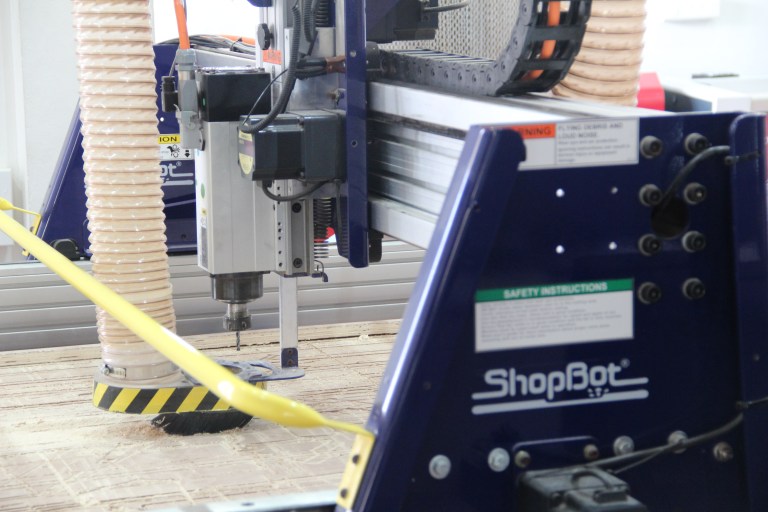
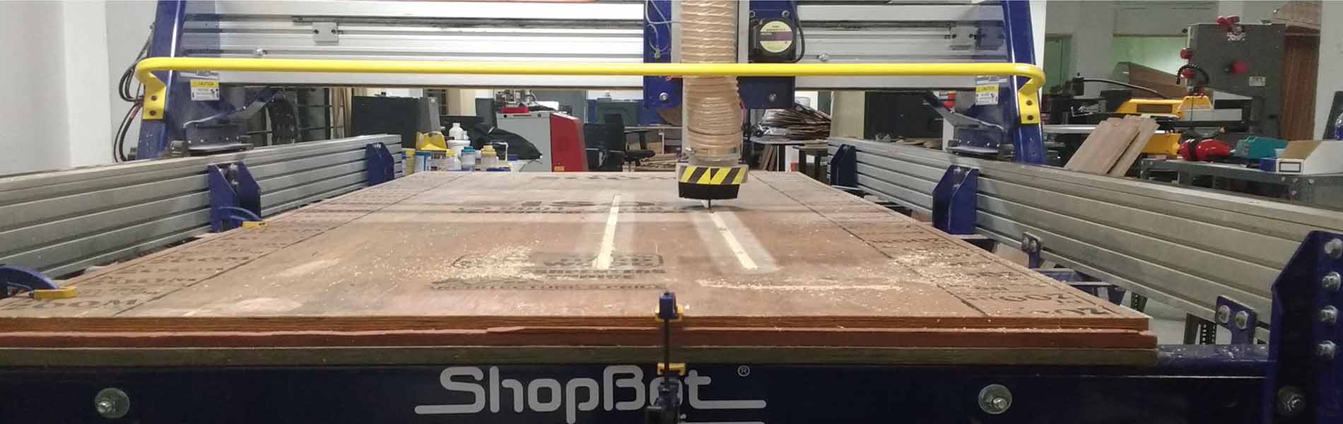
Founded in 1996 in Durham, North Carolina, ShopBot Tools, Inc., designs, manufactures and distributes CNC (Computer Numerically Controlled) routers for milling, drilling, and cutting of wood, plastic, metals and other materials -- powerfully, precisely, and affordably.the machine in our lab can cut 4x8 feet stock with 3 axis movement
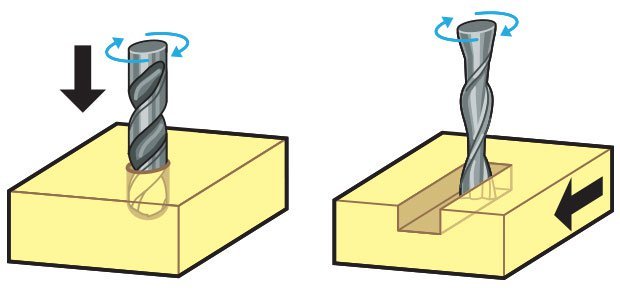
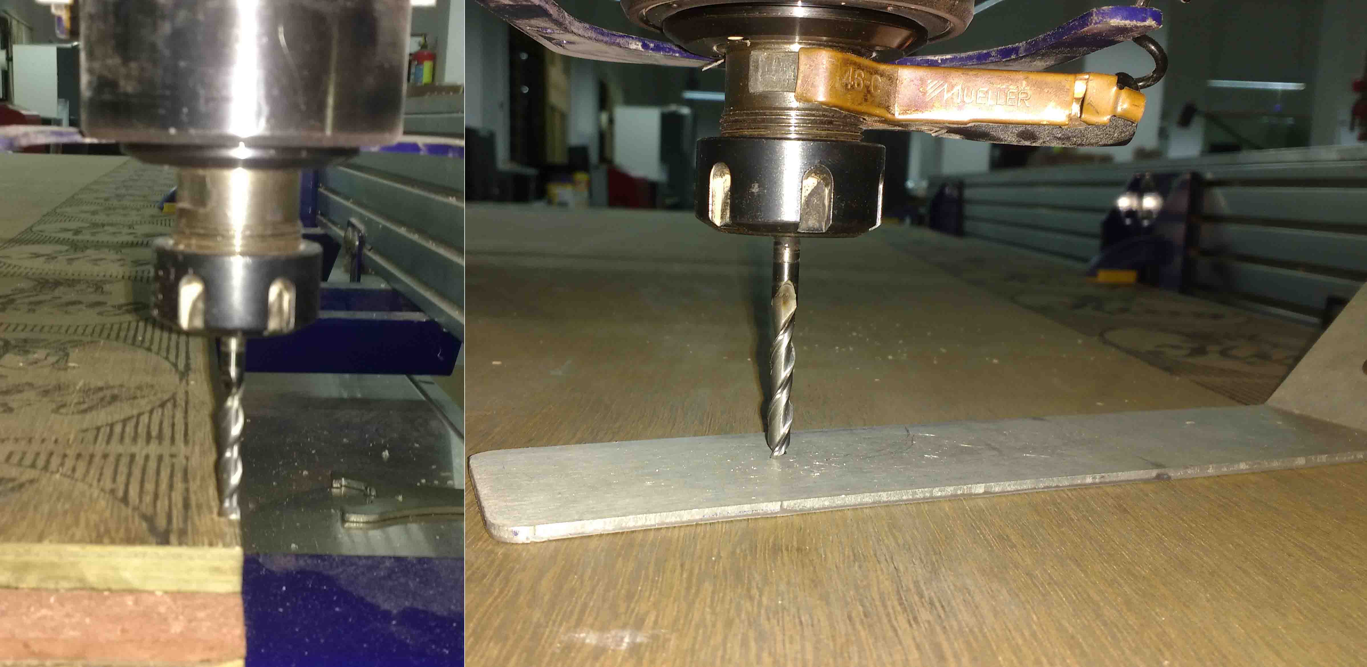
Drill plunging axially on left, endmill cutting laterally on right. if you want to know more w=about it just go through this page
flat end leaves flat surface profile on the stock and are good for removing large volume of material, but steps are formed when used for making curved surfaces. Ball end leaves curved surfaces and forms smooth curved finish while cutting cavities. They are used for finishing cuts.
Chip load :- This is the amount of material that is removed in each chip. The value is approximately = feed rate (inches per minute) / (RPM x number of flutes)
Cut depth :- This is the measure of how deep the end mill should go in each step while milling. Ideally cut depths should be less than 1/3rd of the length of the tool. They are mentioned in the product manual of the tool bits.
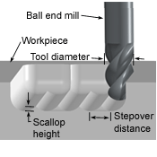
Step over :- In a pocket cut the machine will traverse the entire area of the cut. It does that with a series of paths that cover the entire length and width of the cut. While doing this the step over determines how much the adjacent paths overlap each other. Usually we use it at 50%, ie the adjacent end mill cuts will overlap 50%, which gives a better finish.[Thanks Rahul]
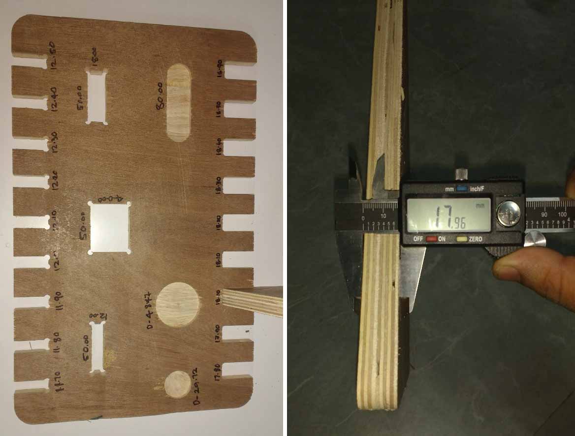
This was our group assignment to find the press fit dimension for the 12mm and 18 mm plywood .So we cut slots from 18.90 to 17.80 in steps of 0.1mm and for 12mm from 11.70 to 12.50 in steeps of 0.1 mm.
We found out that the right fits comes somewhere near 18 mm and 11.7 mm. The material thickness does vary a bit with temperature ,moisture etc.
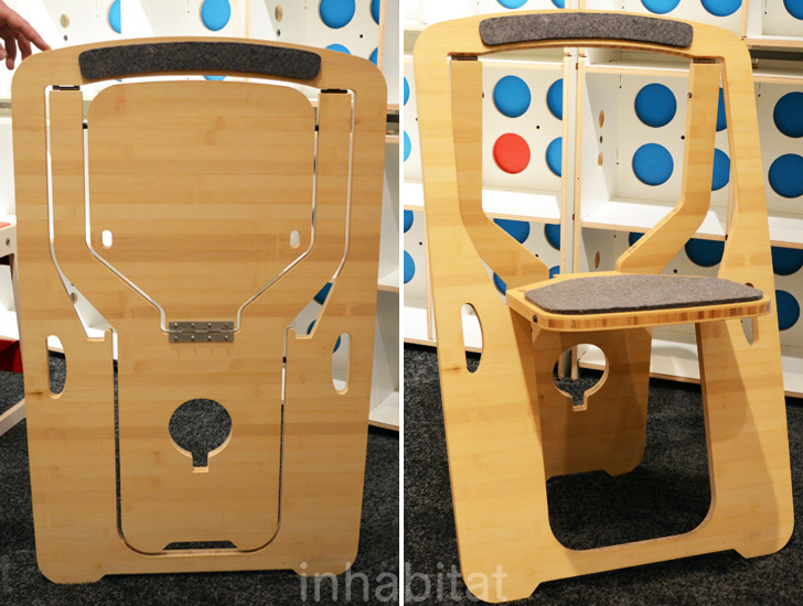
Initially i decided to modify a single piece foldable chair i found in pinterest.In the current version they were using metal hinges .So i decided to use living hinges instead of metal hinges so that the chair could be used as soon as it take from the cnc . I needed some sort of living hinge that is flexible but not elastic in nature .
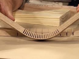
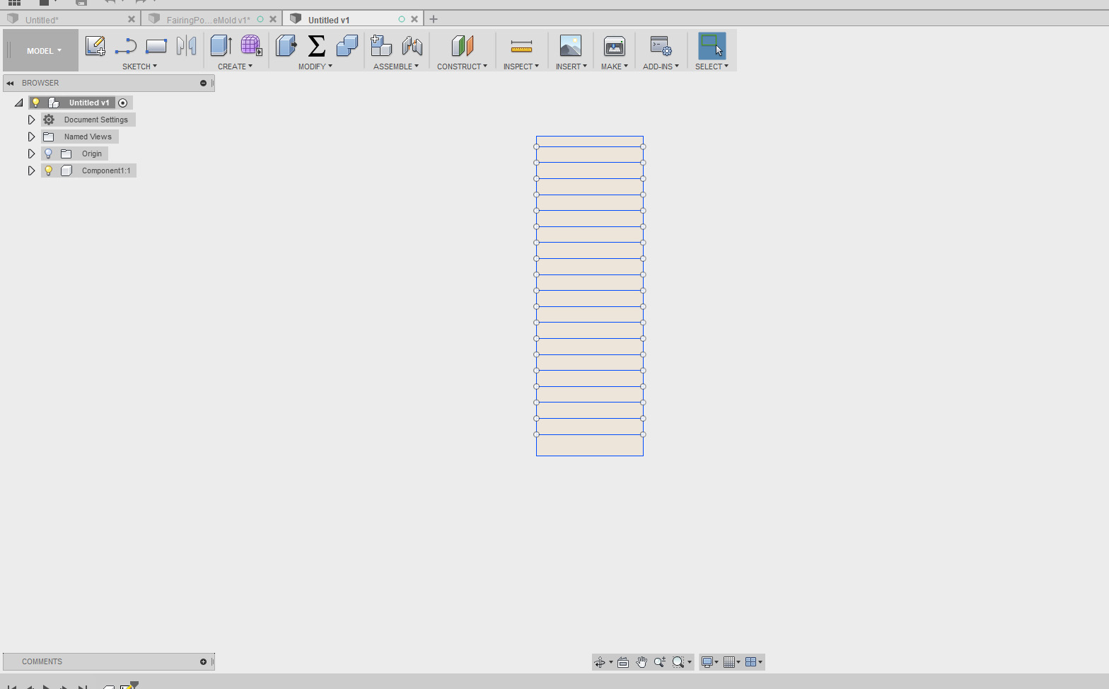
So i decided to use the kerf bending profile . I Draw a sample in fusion and made a sample cut with shopbot
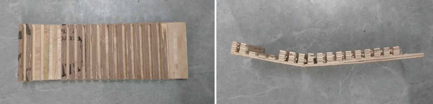
Remark! As i routted my design i found ,Though i used 2 and 3 mm width for connecting adjucent links the fiber made plywood is not flexible enough.I have tryed same type of kerf bending in MDF befor at that time it performed very well. I think today it faild because i used fiber made plywood . since our lab doesnot have any MDF available I decided to switch my design.
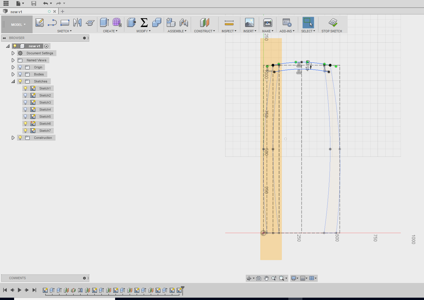
Since my living living hinge faild so miserably i desided to make a Shelf .I fund a video by patrick.rainsberry It is very helpful if you are using fusion 360 for designing your project.
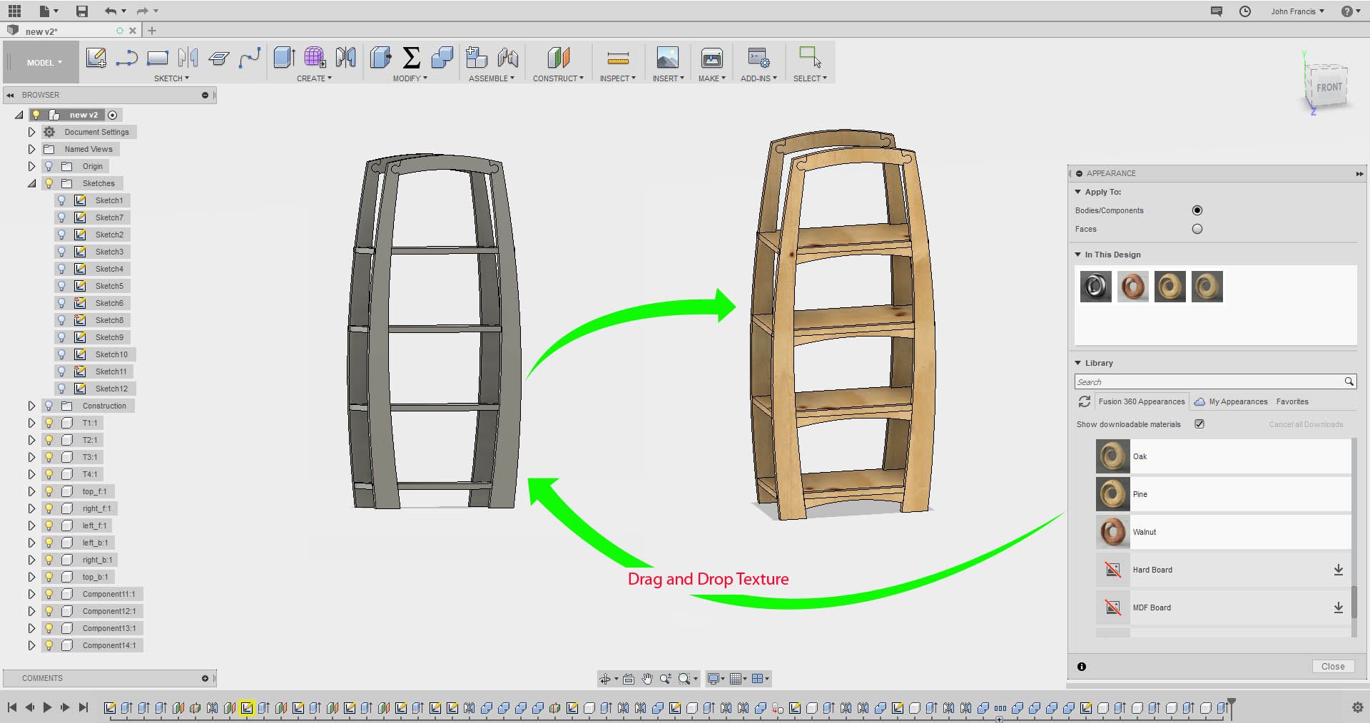
In fusion we can easly add texture material inside the software itself .
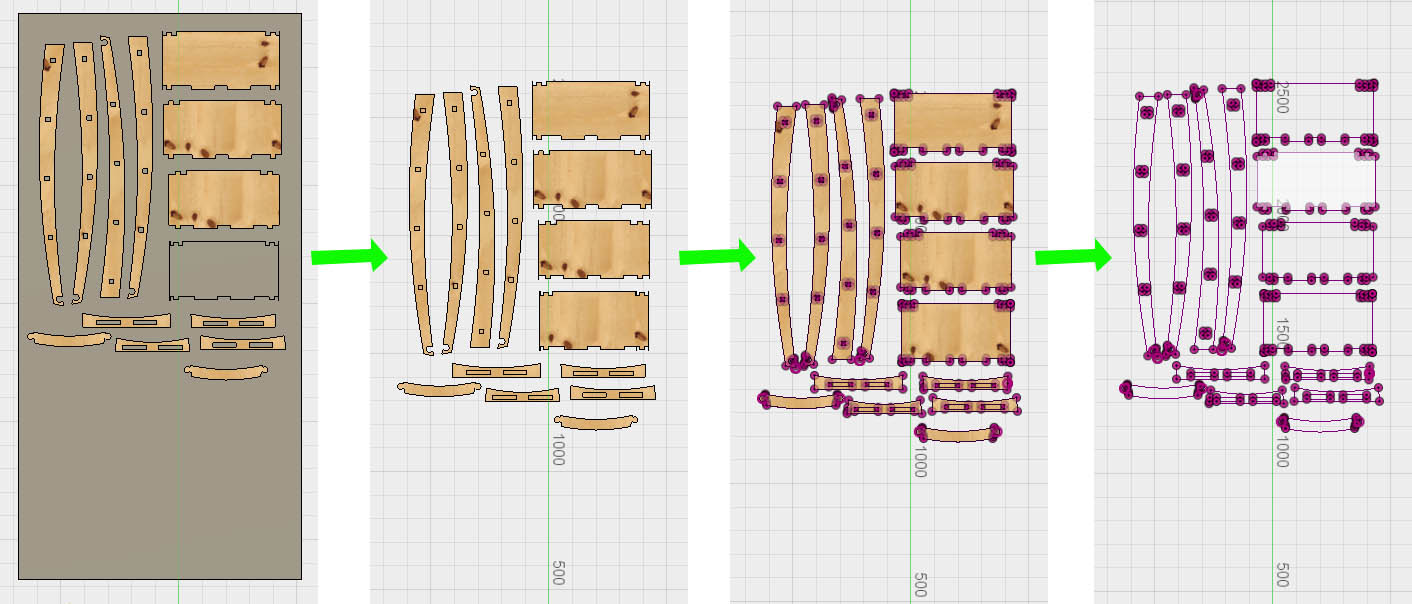
We can make 2D drawings from 3D designs in multiple ways. The one i used is
My completed Design.
I scaled it to fit inside the lasercutter and adjuested the holes to 4 mm .I cut the design in cardboard and assembled it
3D file
DXF file
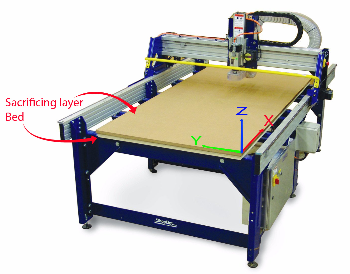
Shopbot is a 3 axis machine the Z axis is perpendicular to the bed .The X and Y axisis are the length and the breadth of the machine respectively.To have a riggid supporting layer on the bottom of the workpiece we will place an additional piece of plywood above the bed called sacrificing layer .The sacrificing layer also protect the millig bit from damage by avoiding unwanted intereference with the metal body.
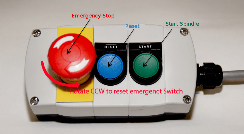
Shopbot has a wired remote which consist of an emergency button,A reset switch and a spindle start button.
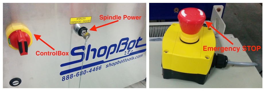
All the electronics are integrated in to the shopbot main control box.It has an ON/OFF switch and also a key to enable the spindle.Shopbot also has an additional emergency stopbutton to place on the other side. So that user could access energency button easly from both side of the machine.
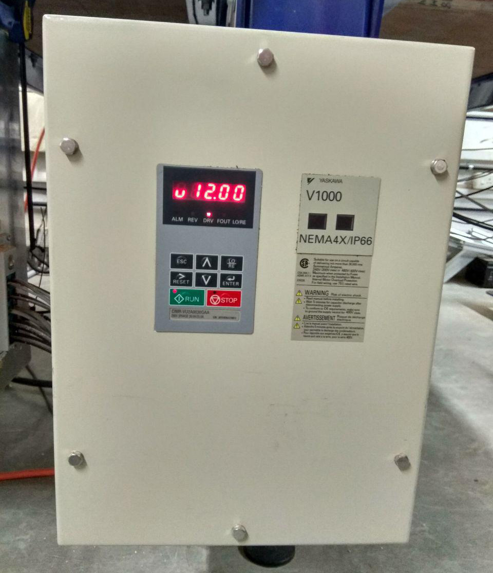
The picture shown above is the electronic speed controller for the spindle motor.
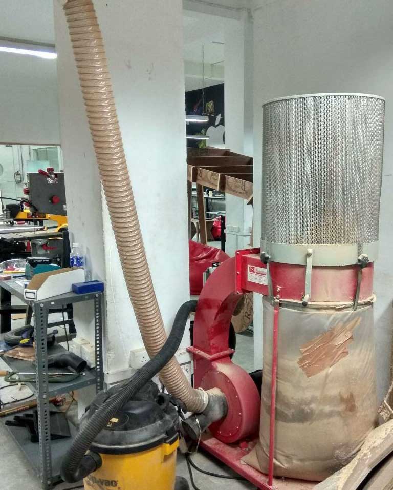
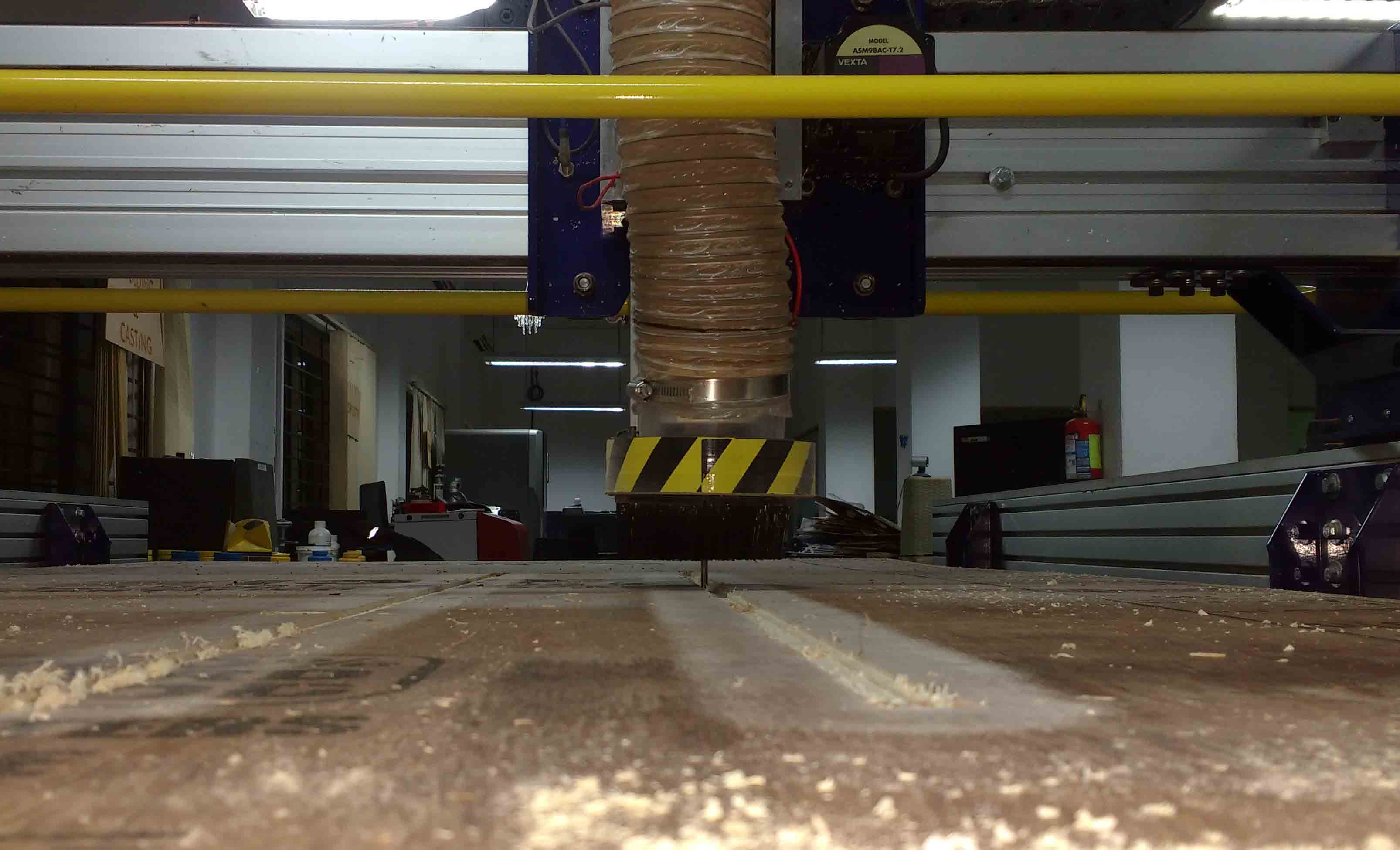
Since cnc machines are working close to human enviournment. We need to have proper arrangements to keep the place habitable to tha person also . Shopbot depends on these huge vaccum cleaner to suckout residues created during milling.
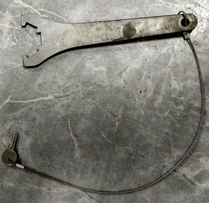
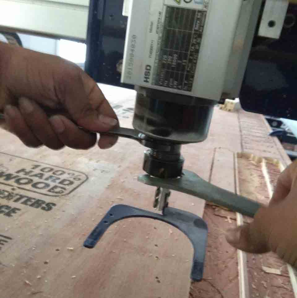
To prevent accidently turning on the spindle while we working on the chuck . The key for the spindle is attacked to the chuck releasing tool.
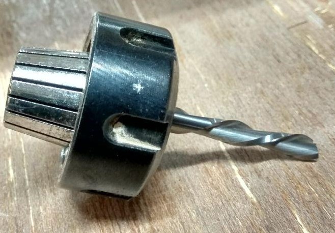
This is the collet which attach the milling bit to the spindle depending on the size of the bit we can choose different collets.
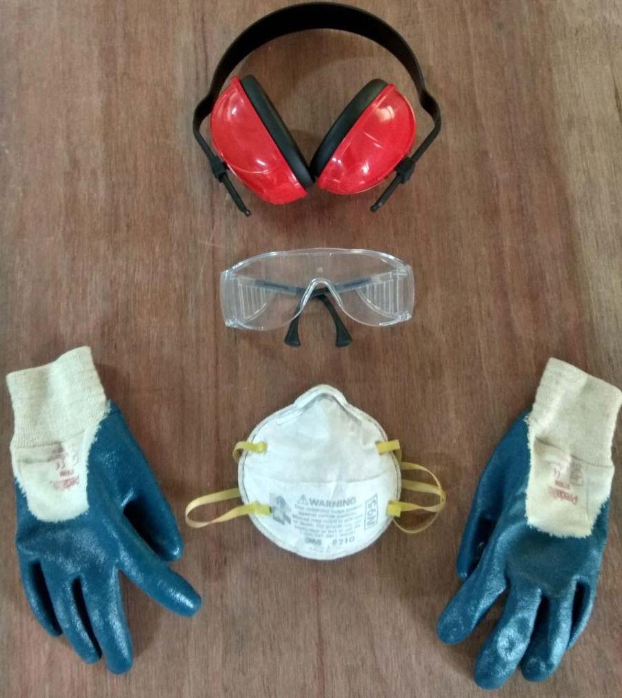
Safty first . Since plywood is rich in small fibers it is essential to use glows, mask and googles also use earphones to avoide any ear damage
Open VCarve pro .Start a new project specify the length width and thicknes as 2040,1220 and 12 respectively.open the new project and go to File -> import ->DXF and open your model.
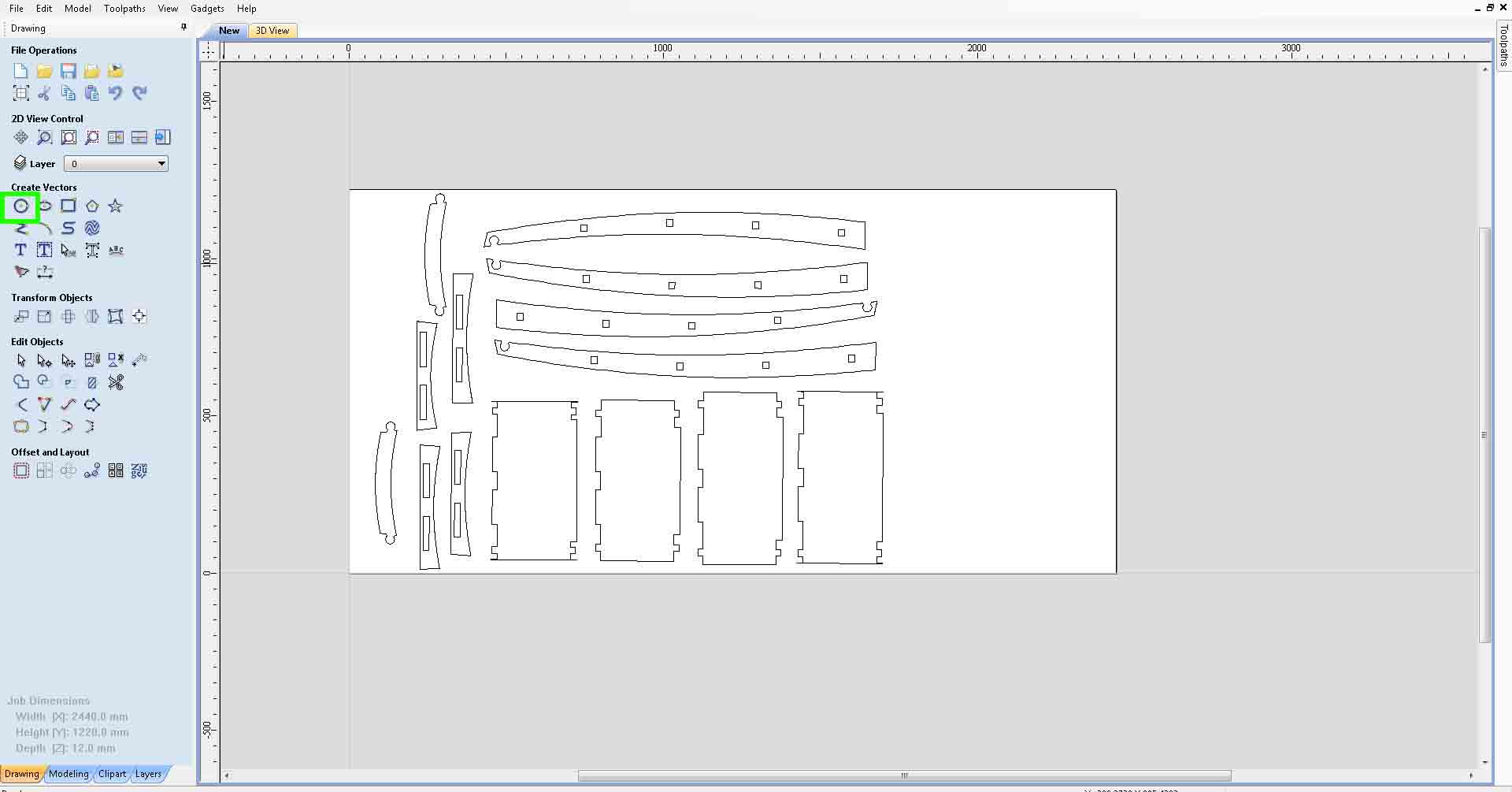
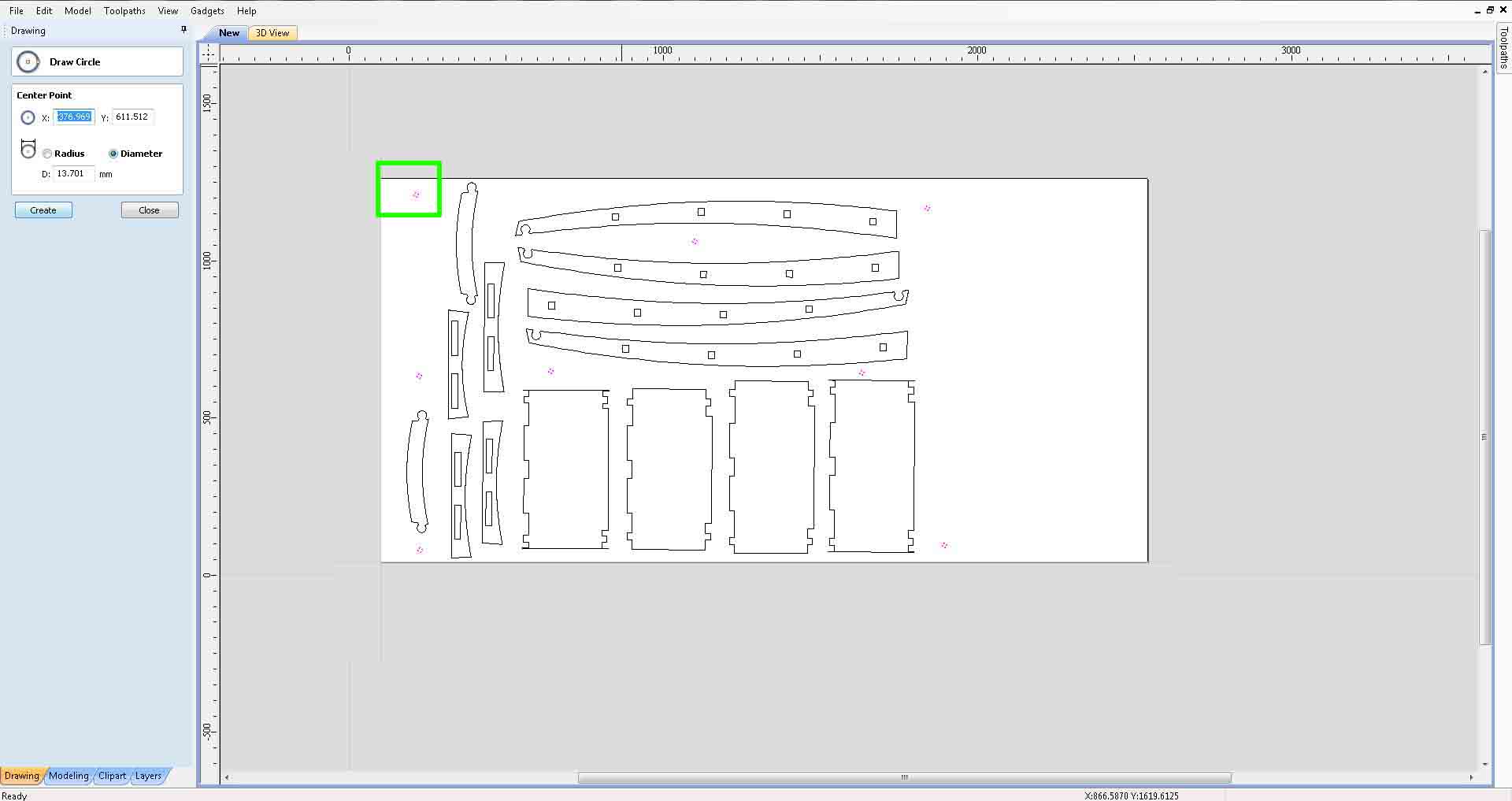
To arrest the movement of work piece while milling we have to screw the work piece to the sacrificial layer . Since we don't want our mill bit to interfere with the screws we should plave them in safe places.The easiest way is to find out the suitable position using the machine itself.!st place some holes in some safe positions in the model using the circle tool.use a slightly bigger circle than the dia meter of your tool.
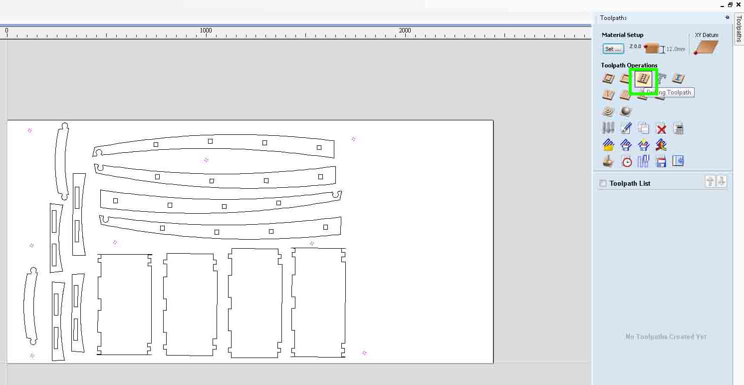
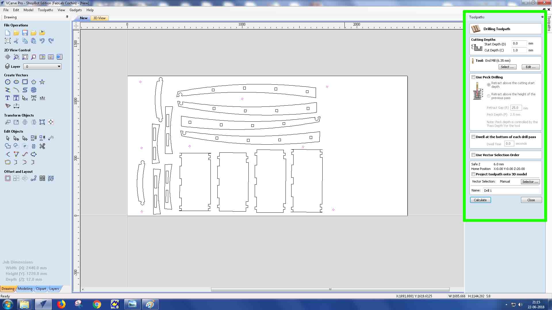
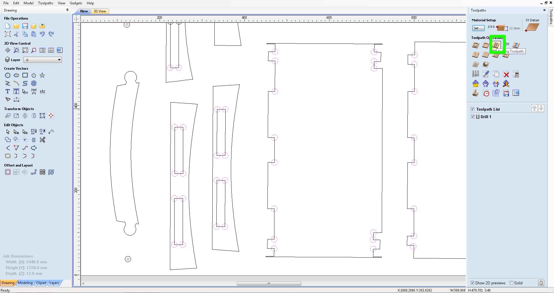
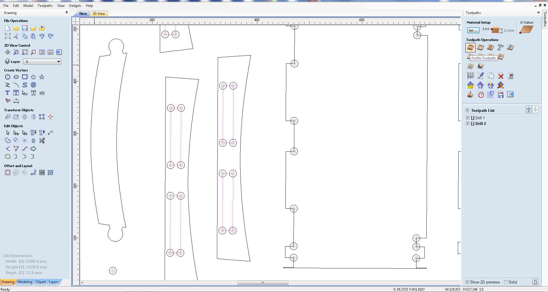
Select the button to generate the drill tool path.
Select all the screwing holes choose 1 mm depth to cut and generate tool path.
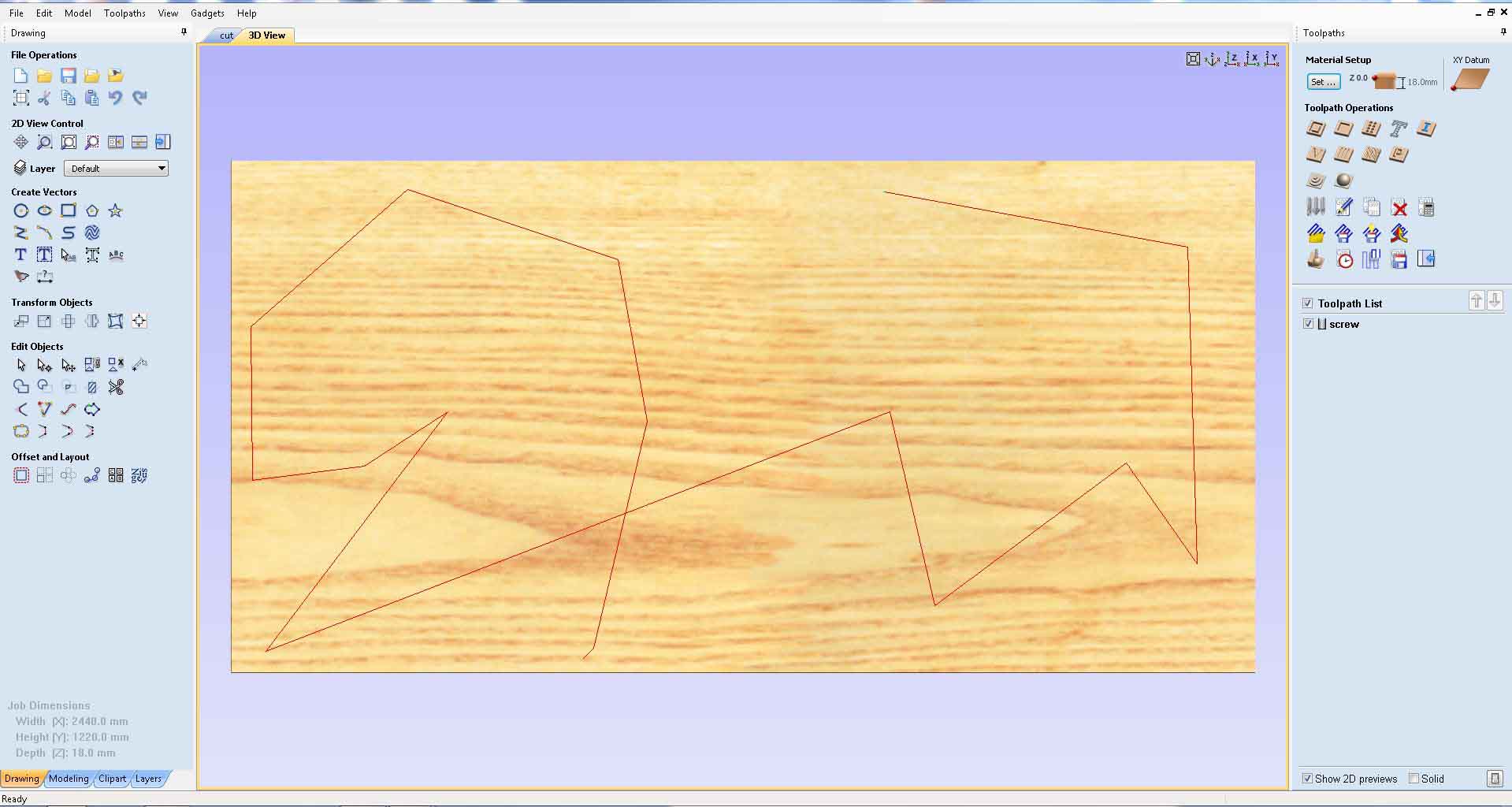
The V carve will generate a visual feedback by checking the simulating we can modify the file if we wanted.
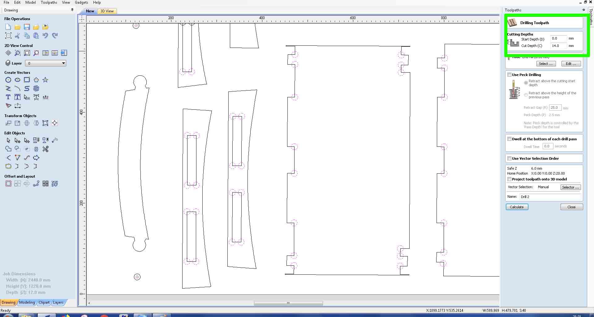
Next we need to drill holes in all corners to enable the complete incertion of the press fit . We can also use the dog bone add-in in Fusion 360 to achieve a better result .But my Instructors adviced me to try this for the 1 st time and use the add-in for later uses.
Select all the circles . In our cnc our sacrificial layer is not uniform sometimes we observed a level difference of 2 to 4mm in some places.So iI decided to add an extra 2 mm ti the drill depth just to ensure the completion of drill process./p>
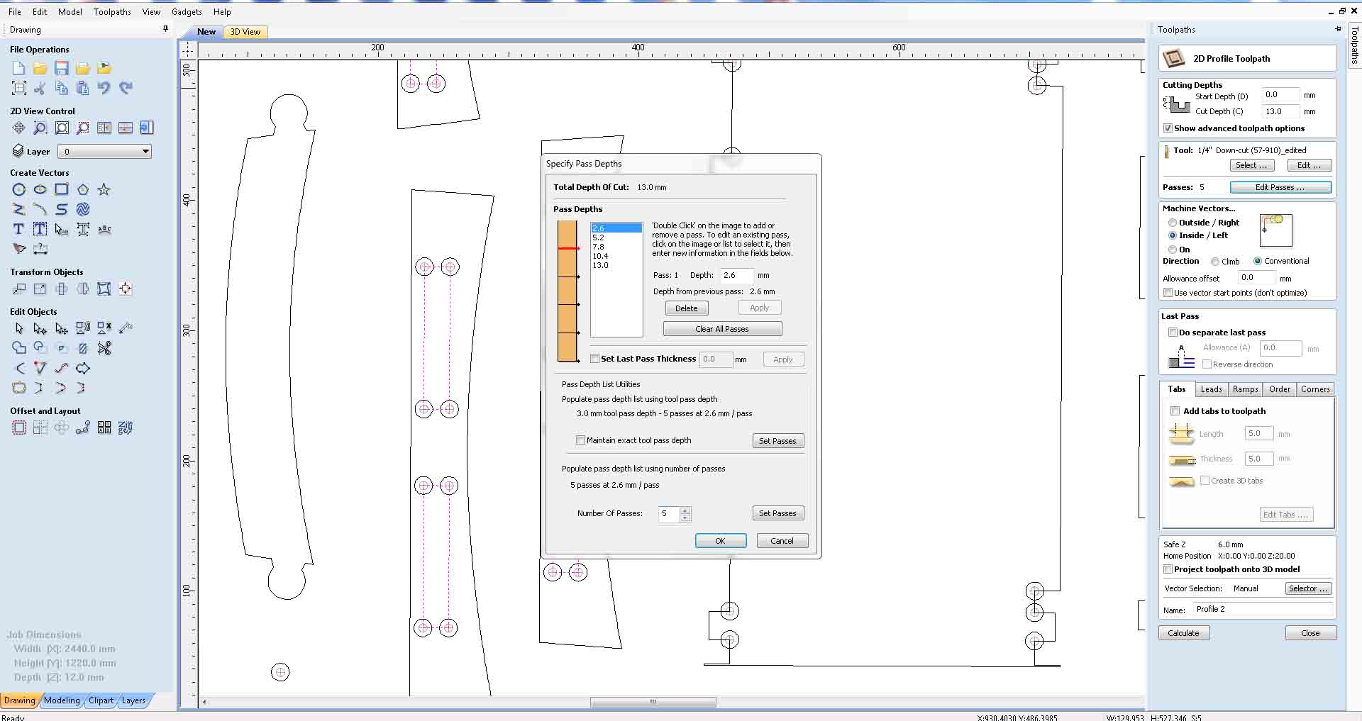
Next select all the inner cuts.This time choose the profile tool path insted of drill.
I wanted the inner cuts to be have a depth less than the thickness of the plywood so that it won't be observable from the outside I decided to choose cut depth as 9mm I kepthe number of passes 5 . because some of my friends already brocken 3 bits .So I was affride about the lifetime of the milling bit.From machine vectors choose Inside cut .Choose calculate to generate the tool path.
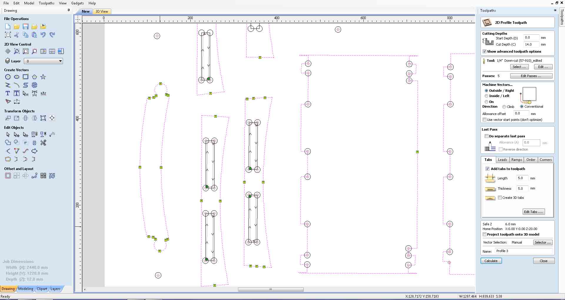
Next we have to cut the outer profile .I choose full depth cut + 2 mm extra to cut the outer profile Remark some of my vectors were open so the software refused to generate tool path .So I had to open the file in rhino and had to join them again. I had to regenerate all the tool path once again.
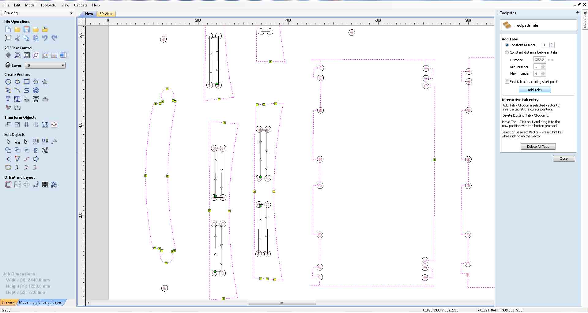
This time choose out side cut. I kept number of passes 5 itself.Next we need to add tabs .Tabs are small uncuted pars in the model which will keep the plywood pieces in place untle the cutting will complete . We have to manuely remove the tabs once we completed the milling.
To add tabs just click on the "add tabs button"You can manuely tabs but I used automaic .I choose a tab in atlest every 200 mm and maximum number of tabs per piece is as 4 and proceed to add tabs . I replaced some tabs In some inaccessible areas. The tab diamensions were 5 mm long and 5 mm thick.
After completing tha tool path generating i simulated the cutting .It performed well.
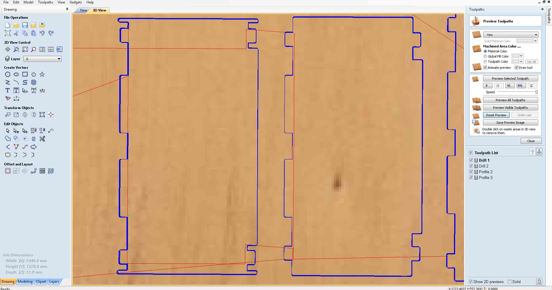
To save the tool path select the tool patha click on the flopy disk icon
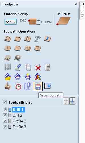
Click the button "Save Toolpath to File" and save it.
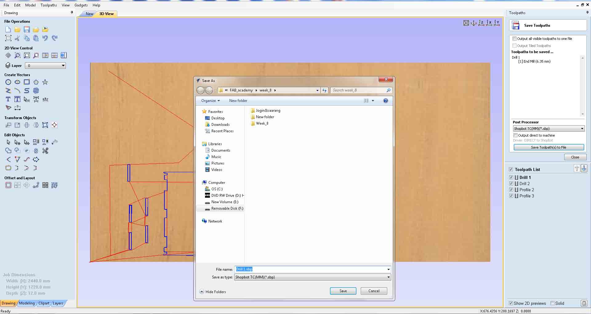
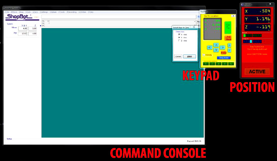
Next we have to open the file in the shopbot application.
The software has a simulated DRO(Digital read out) and it has 3 main parts
Change the drill bit to the appropriate one
Jogg the endeffector to the desired origin point and click in the zero axis button .Select X and Y axis and set to zero.To set the Z axis move the endeffector tho the center of the board . For zeroing the z axis we are using the automatic methode place the zeroing plate directly under the milling bit .Connect the clip to the spindil and click the z Calibration button

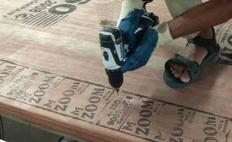
!st drill the holes for mounding screws. Drill and screw them.
Load the cut parts in the order.
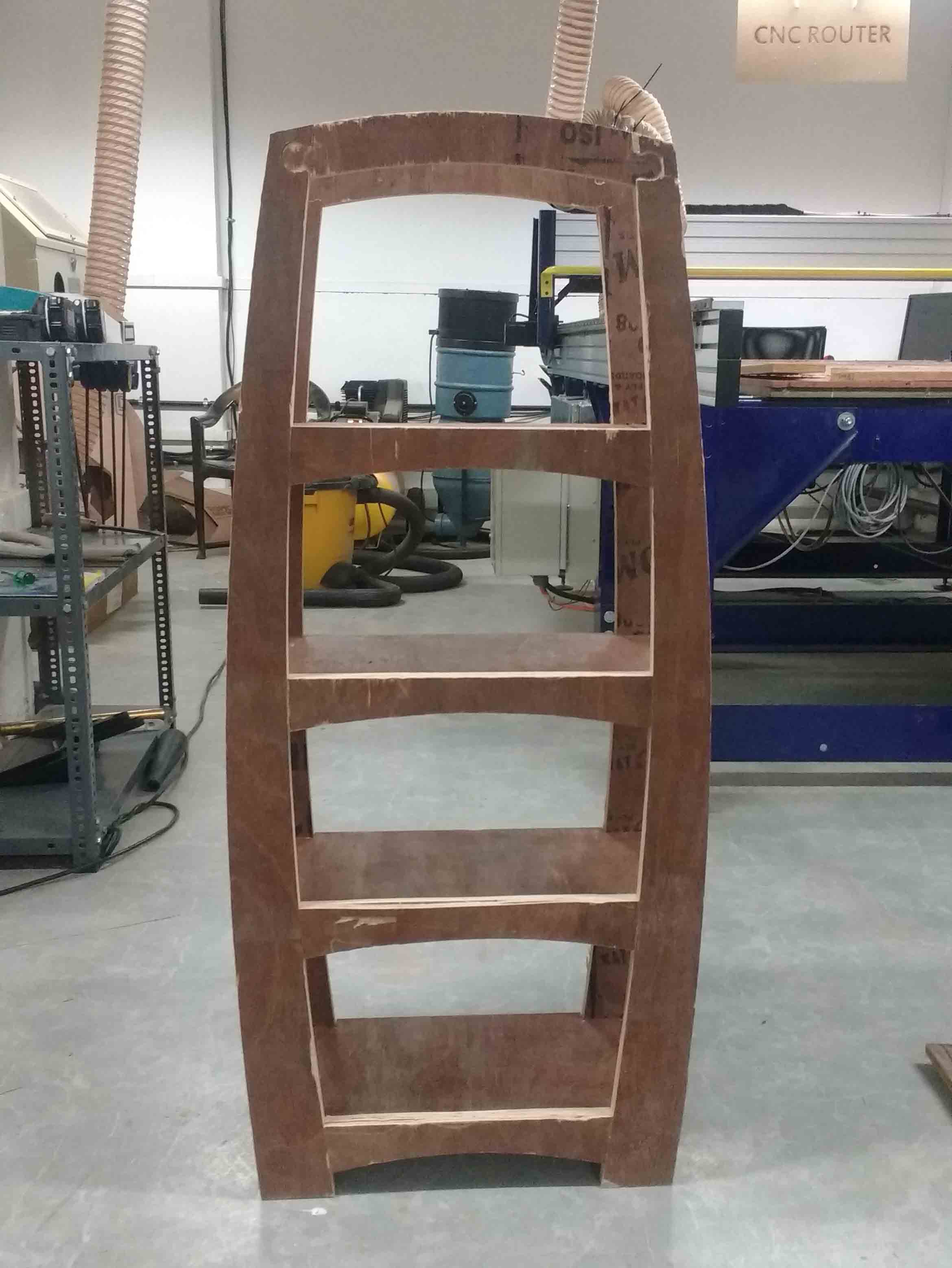
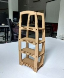
Complete the milling and assembling my shelf.
This is my completed assignment.