This week's assignment is to take an existing Fabacademy design, the hello-world board, and add a button and an LED (with current-limiting resistor), check the design rules, and make it (if you have time, test it).
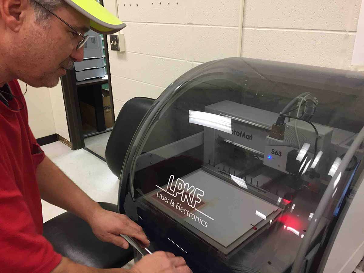
I started by reaching out to my instructor, Chris Rohal. Chris is the go to guy at LCCC for electronics. Chris explained that we would be using a different desktop mill this week, called an LPKF ProtoMat S63. The LPKF is a more sophisticated mill than the Roland. It has a high speed (60,000 rpm) spindle, and a 15 tool automatic tool changer. The most important feature of this machine is that it can successfully mill very narrow traces. I have never used a machine like this before, but I wanted to learn.
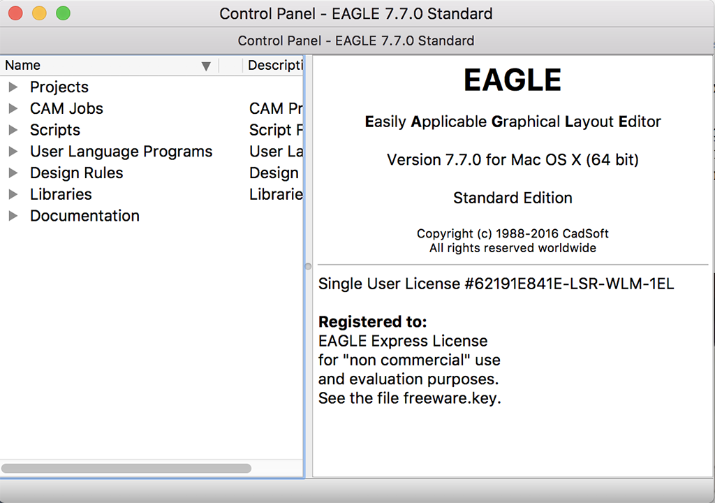
The other thing we would be doing this week is using a CAD package to modify a circuit board design. I have been doing everything on a Mac laptop, and Chris suggested I use Autocad Eagle. I had some issues installing the latest version of Eagle, a problem which is well documented among many users. I worked around this problem by using an older version of Eagle 7.7.0 which was developed by CadSoft, which was later bought out by Autocad. I believe the issue of being able to download the latest version for Mac has since been fixed. There is a Fabacademy tutorial on Eagle here:
http://fabacademy.org/archives/2015/doc/electronics_design_eagle.html#step2
It is a little out of date, but it helps explain how to use Eagle and how to apply Eagle to what you need to get done with this lesson. There is a link to an example hello_world board there, but it is a dead end. No worries, learn how to import the fab.lib file to your package and just add the components.
(id='select')
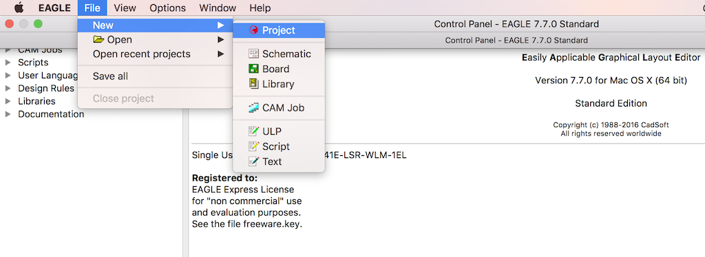
You can start by opening a new project with the command sequence File - New - Project which opens up a file tree to name a new project.
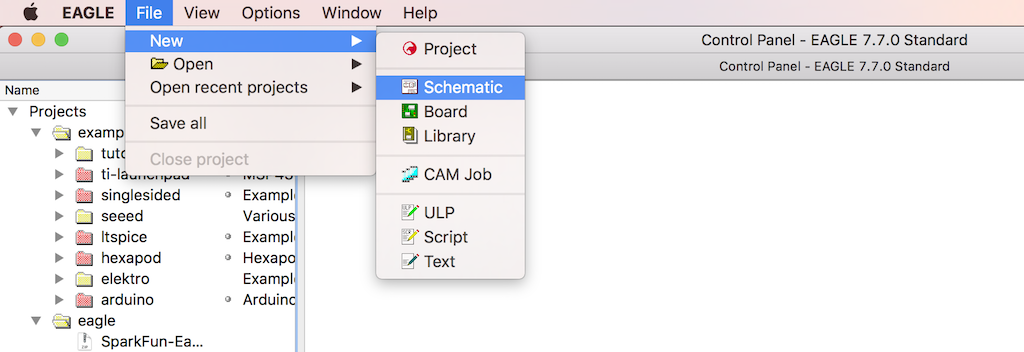
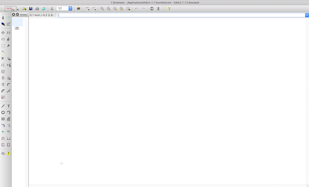
Next, you start by opening a new schematic with the command sequence File - New - Schematic.
You end up with an untitled schematic which you can name later. As I work on a project, I keep saving the file because the Mac version crashes ALOT! When I make significant changes, or I want to try something I am not sure of, I save my last good schematic with a tag, such as R0 for revision zero, or R1 for revision 1. That way if I really get messed up, I can roll back to an earlier version.
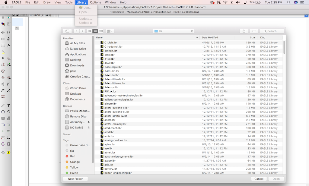
Next thing to do is to open up a parts library. I had downloaded the Fabacademy parts library earlier. You can add the Fabacademy library by the command sequence Library - Open. Rename your most often used libraries with numerals so they end up on the top of the list. This makes life much easier and pleasant when navigating. I also like using Adafruit's library, and many of the items you find in the Fabacademy library, you will find in the Adafruit library. The founder of Adafruit is a Gershenfeld disciple.
(Fabacademy Library File: 01_fab.lbr) (I have an underscore that the hot-link might be obscuring. File reads 01_fab.lbr, links to 2017 repo)
(Adafruit Library File: 01-adafruit.lbr) (You should right click and "Save As" if you want to download these, links to 2017 repo)
After you added the Fabacademy component library, you are ready to add components.
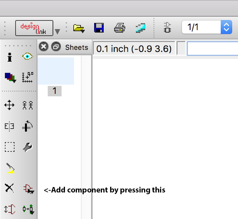
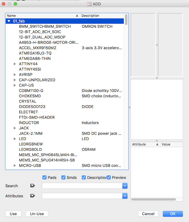
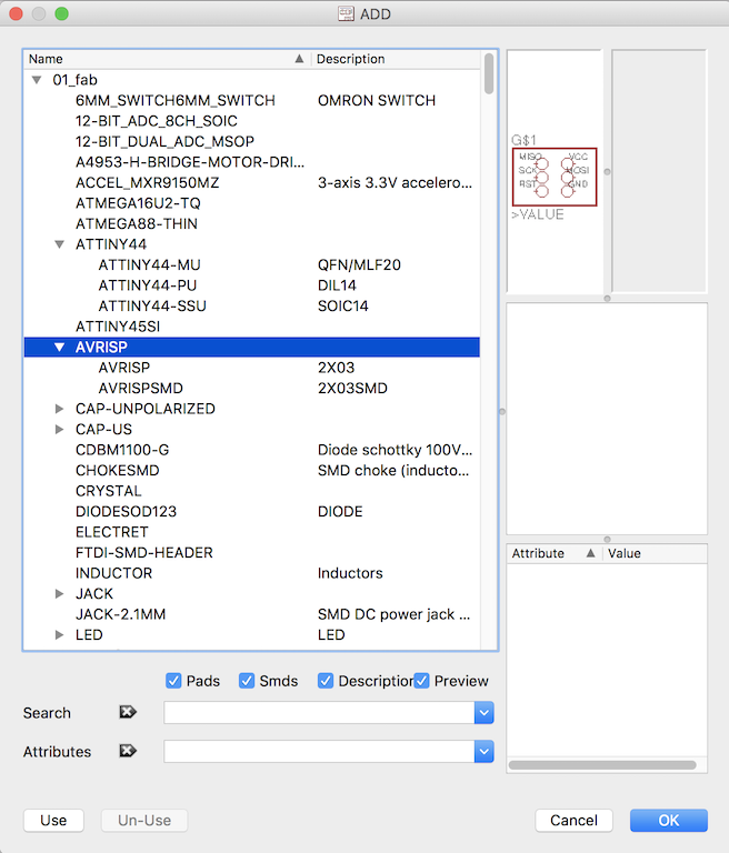
The left side panel is where you will find most of the tools you will need to complete your schematic. If your not sure what the icon does, mouse over it and wait for a yellow cloud to pop up to tell you what it is. The ADD component button is shown above. Press it to get to the next screen.
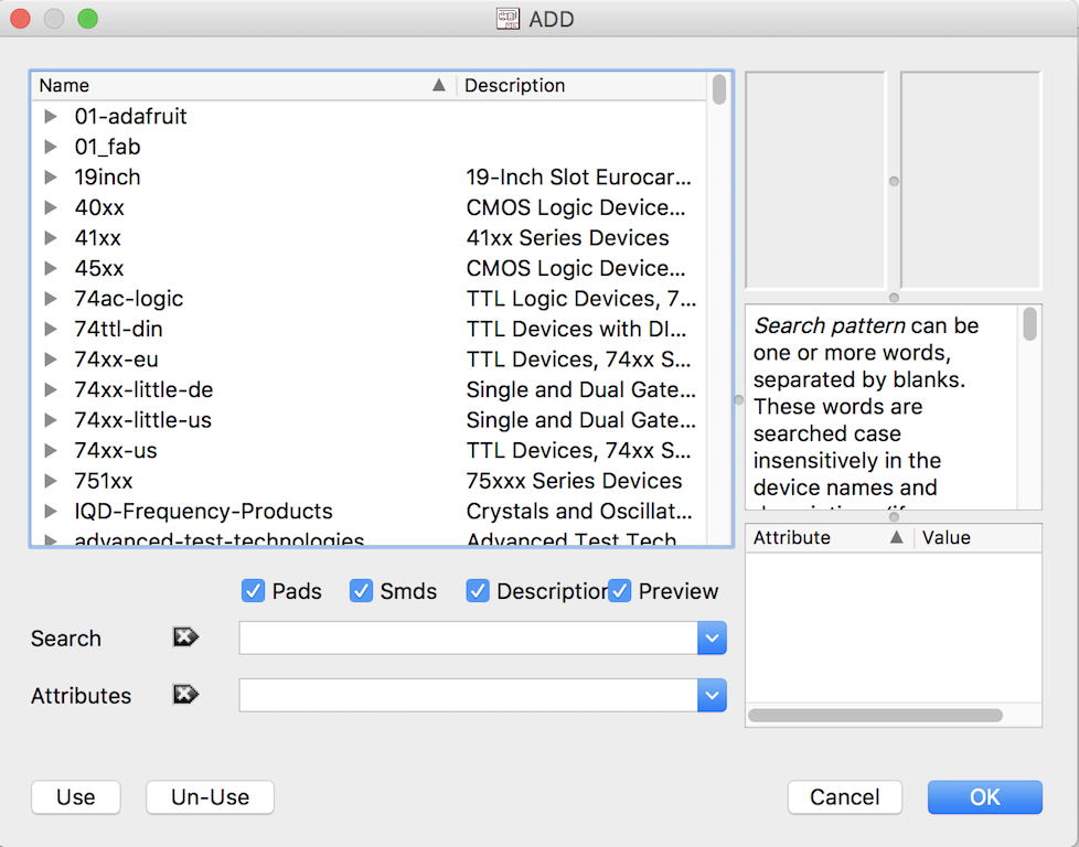
Click on 01_fab for the Fabacademy library. You get a pull-down menu of components.
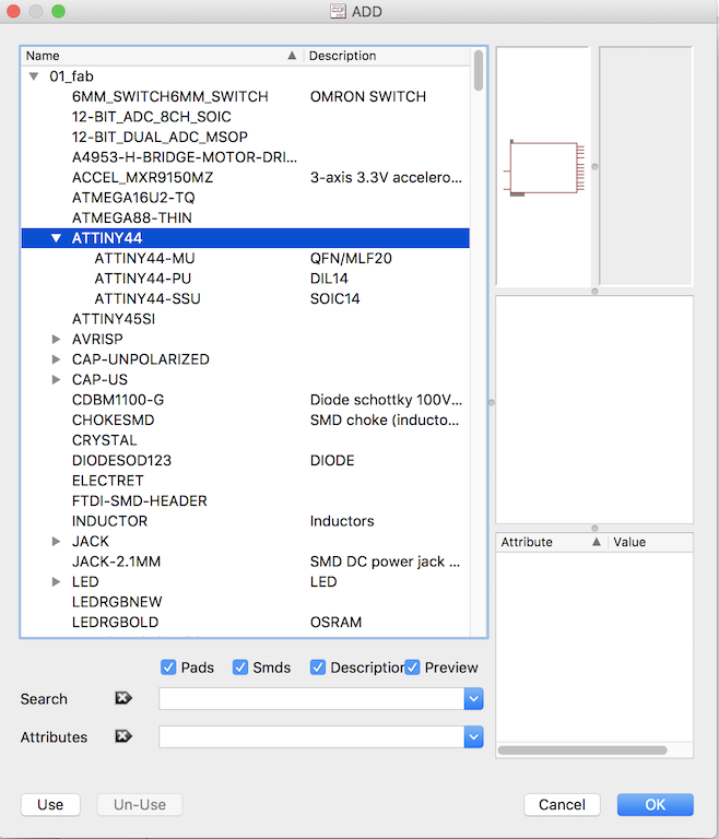
Next, look for the main component for this project, the ATTINY44. There are three flavors of this processor in the library. The one that I was told we would be using is the ATTINY44-SSU which is a surface mount, small-outline component.
The ATTINY44 is listed three times in the Fabacademy library, depending upon which package you would like to use. A good reference regarding integrated circuit packages can be found here: https://learn.sparkfun.com/tutorials/integrated-circuits/ic-packages
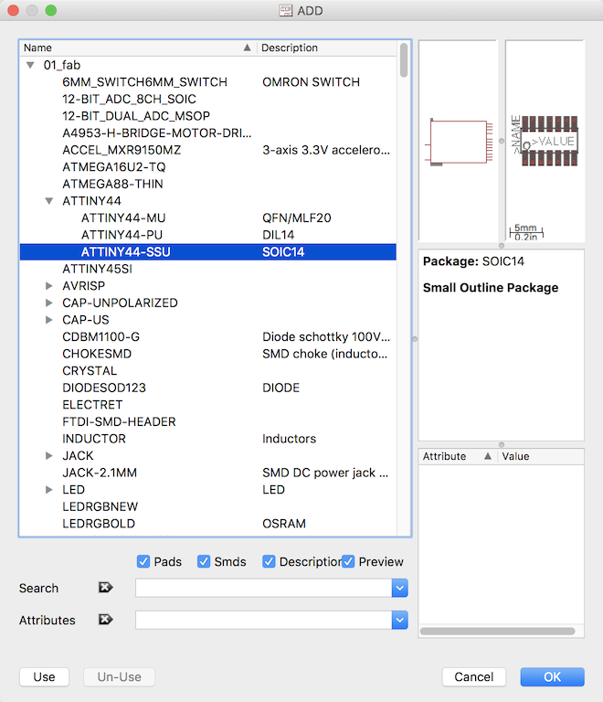
Once you click on that component, a schematic drawing and outline drawing appear, which helps you verify you are selecting the component you are looking for.
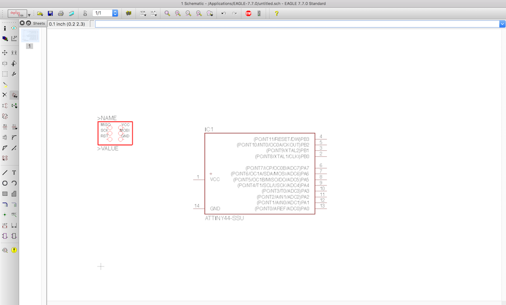
Next, you automatically flash into your workspace and your cursor morphs into the outline of the component.
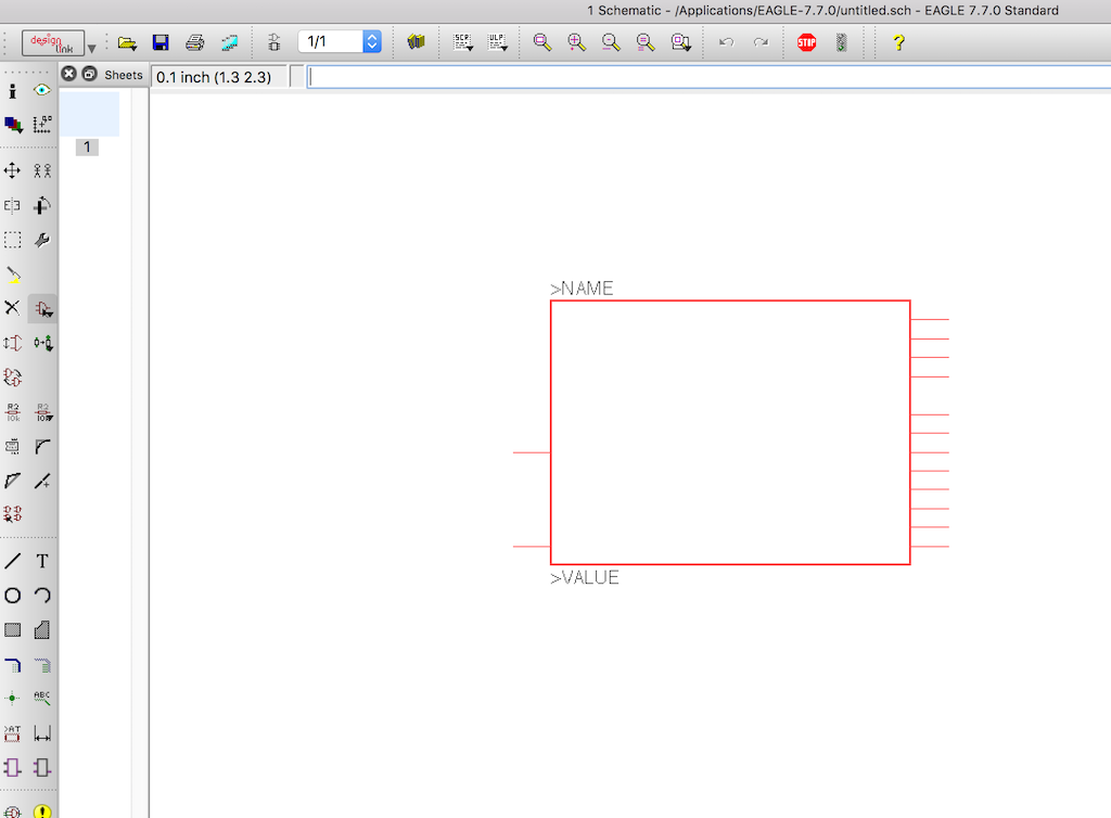
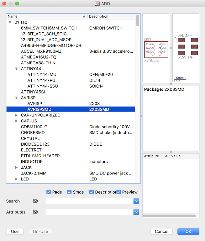
You click where you want to place the ATTINY44 in your schematic. Once you place it, it populates with all the named values for the pin-outs. Press escape to extinguish adding any more ATTINY44's to your schematic. You only need one. Next, go add the AVRISPSMD component. This is a six pin header which you will plug in a ribbon cable. It is a surface mount component.
Make sure you use the SMD flavor of the component.
Your schematic should look something like this now.
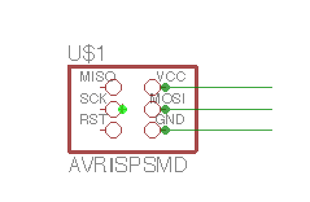
Next add some wire to the AVRISP header.
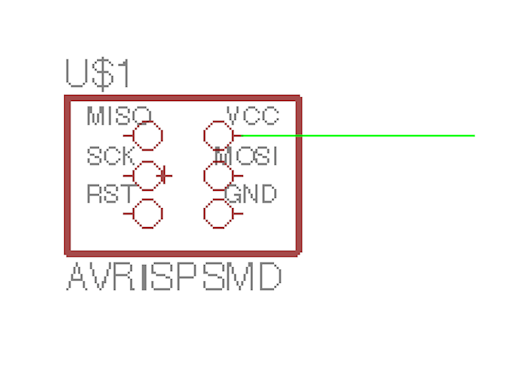
Draw wire from each pin of each device. You can drag the wire and connect to other devices later. I feel it is good practice to make sure the wire connects logically to the component with a junction. You do that by selecting the icon which looks like a little green dot, as shown below.
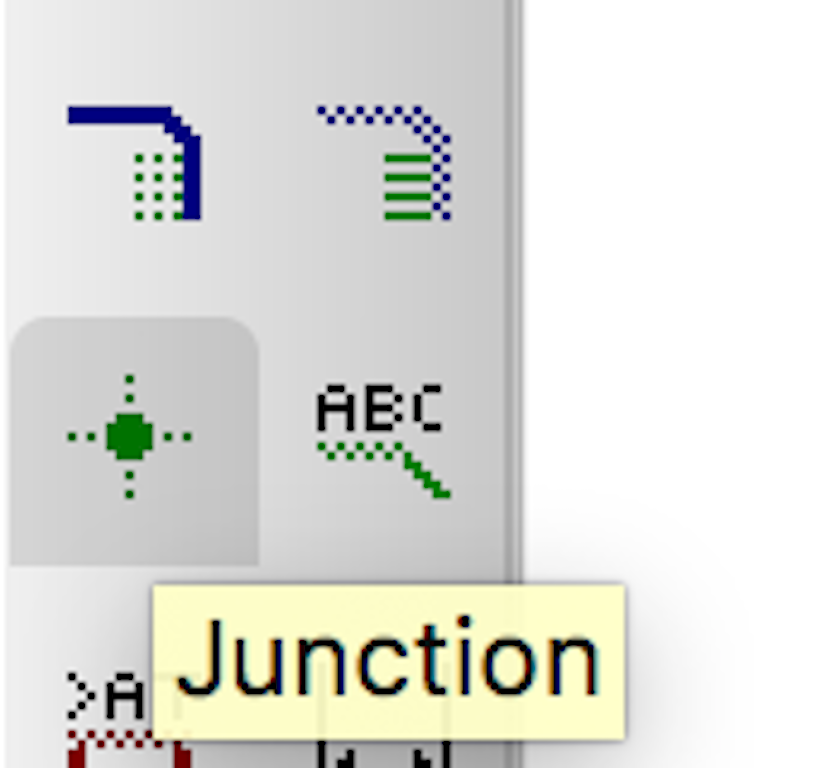
The green dot icon is junction. I always like to connect my wire to devices with junctions. And this is what your schematic should look like once you add them.
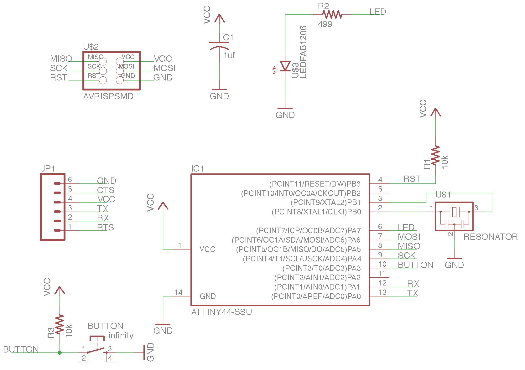
You can right click and change the properties of wires. When wires have the same property name, they are considered connected. Eagle will give you a warning when it is about to do this. Yes, do it. One of the more powerful features of Eagle. You can also right click components such as capacitors and resistors, change properties and change their values to what you want. Later on, when your traces are generated, Eagle will make the components connect, and will label the components with their names and values.
When I was all done, my schematic looked like this:
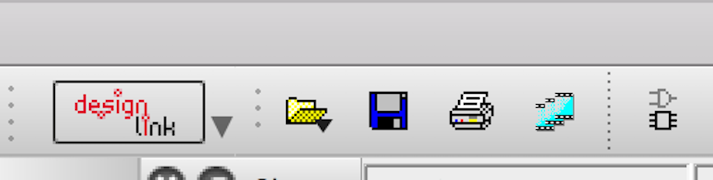
Next, find the icon shown all the way to the right. This is a switch screen button. It will switch you from schematic to board view.
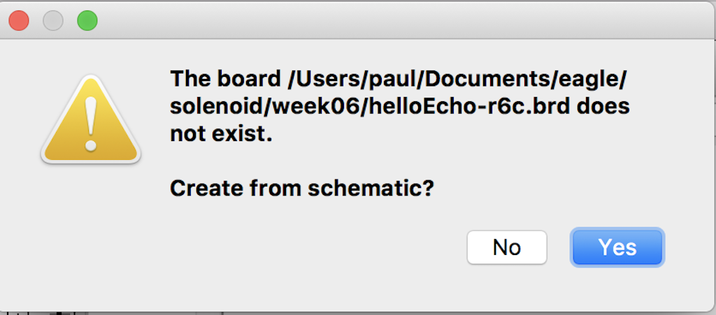
You will be asked to create a board from the schematic. Click yes.
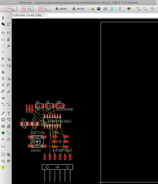
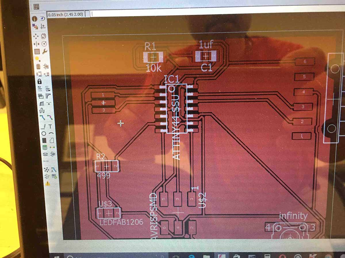
Your board screen is generated. You will next want to adjust the white box to the right to match the size of your PCB blank. You next click and drag the components onto your board outline. Once you drag them onto the board, you cannot drag them off.
Next, you have a couple of choices. You can manually route all the traces, or you can use the Autoroute function. I prefer the Autoroute function. My instructor, Chris Rohal, hates it. I guess it's a matter of style. Either way, it is a reiterative process.
(id='hello-world')
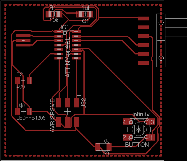
Once your board generates without any errors, you are ready to export it as a PNG file, or use the cam processor to create a Gerber file for the LPKF Mill.
(File: helloEcho-r6.brd) (You may need to right click and "Save As")
(id='demoworkflow')
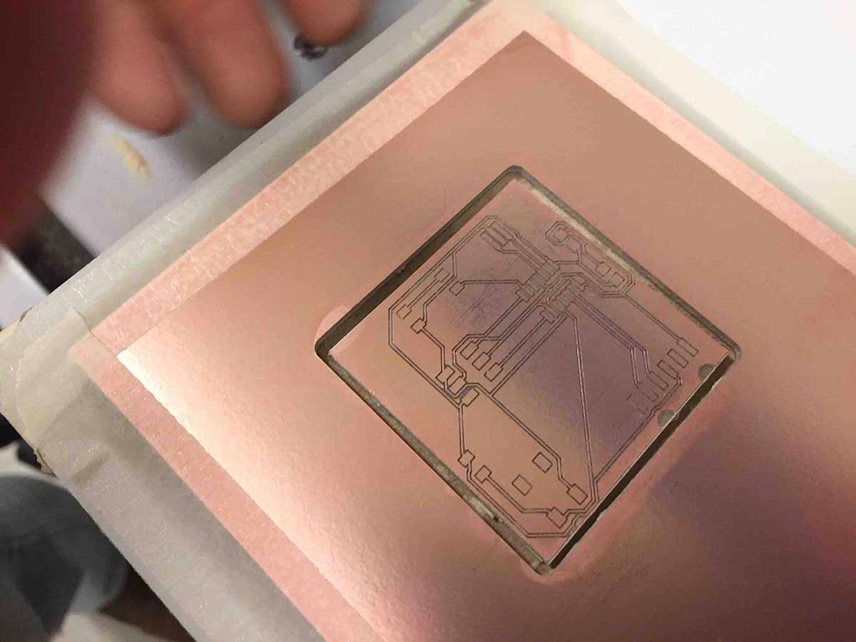
I put the PCB blank in the LPKF. With the LPKF, they suggest you tape the perimeter with masking tape. I did it that way on this board, but I have also used double stick tape with success as well.
The resulting board cutout.
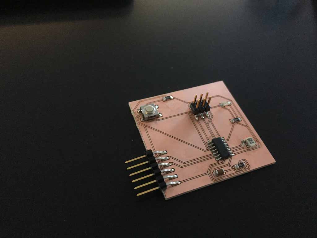
Here is a picture of the board completely soldered with all of the components.
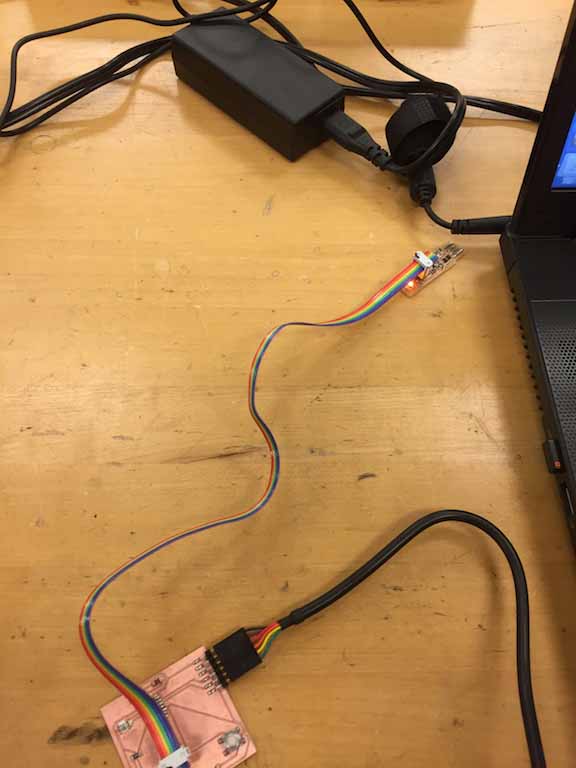
Here is an image testing the board with my toolchain.