assignment
individual assignment:       add an output device to a microcontroller board you've designed, and program it to do something
group assignment:       measure the power consumption of an output device (#power)
(id='design')
My week 13 project is part of my final project. I decided to build a circuit which operates a 12V solenoid valve which will add inert gas (food grade nitrogen) to a wine tank. In the process of testing the board, I fried the motherboard of my Mac laptop which is being repaired. I am in the process of restoring files. Painful....
(id='programming')
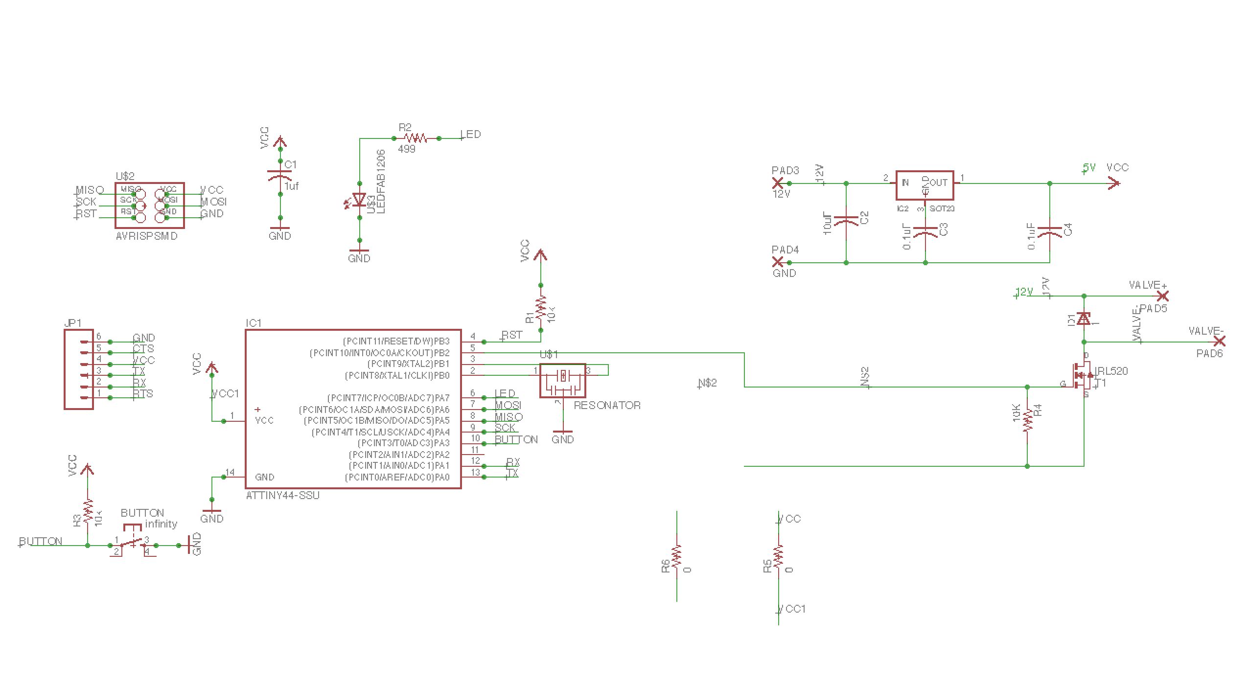
I first designed the board using Eagle CAD and my old hello-echo file. I used the data sheet to find out which physical pins I could use for inputs and outputs, and what GPIO assignments I would need to make in my sketch.
In this design, I performed "spiral development" on the Hello-World Board. Why start from scratch? I studied the Hello-World board and the Atmel Tiny44 data sheet to see if there was enough memory and I/O (input/output ports). There were unused ports on the Tiny44 and I didn't use up that much memory on the Hello-World project, so I proceeded.
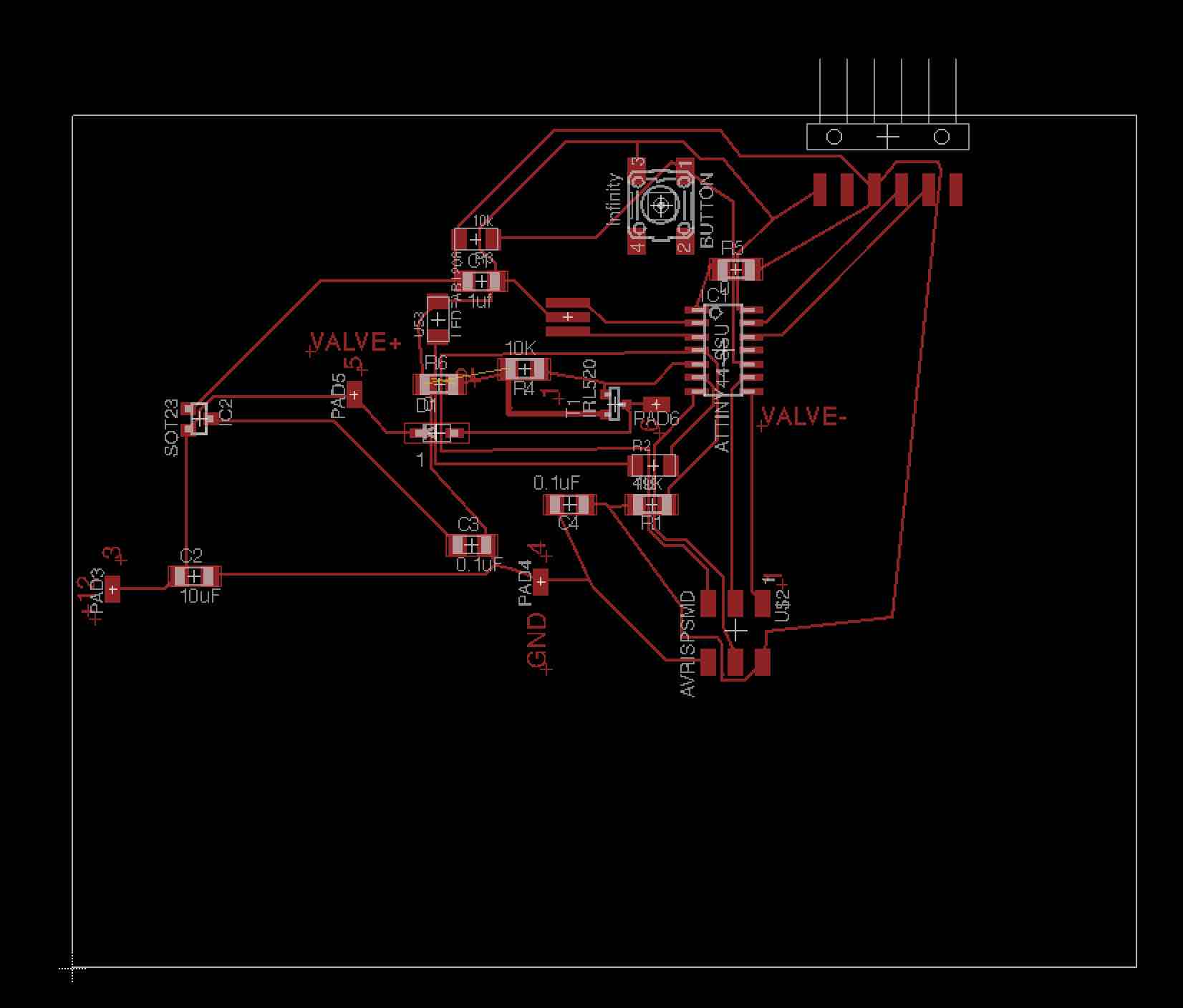
I used the Eagle schematic file from the previous assignment, and made a new copy. I am a big fan of using Autoroute feature in Eagle. I used it when I added the button to the Hello-World board. Here, I have to add some pads and a small MOSFET, press the auto-route icon, and I'm done. Well, not that easy. Eagle dumps all the new components in the bottom left corner, and has you place them manually in their final location. Eagle then calculates the routes for the circuits when you press autoroute, and highlights circuit paths which it found impossible to auto-route. At that point, I delete some of the calculated circuit paths, reposition some of the compoents and try again. Sometimes I find it necessary to place a jumper across a path to get the auto-route to work. I do this by adding the resistor which has no resistance... in other words, a zero (0) Ohm resistor. My instructor, Chris Rohal prefers to manual route his traces and ground the backplane. I am just more comfortable with the auto-route method. Yes, it's a lot of trial and error, but so is manual routing.
I found solder pads in the component library. I needed to add four of them. I added solder pads to hook up flying leads to the board. One pair of pads is used to provide power for energizing the coil that would be part of a solenoid gas valve. The other set of pads would be used to connect directly to the coil. I realized later that you can embed names in the components, and if you draw a circuit, say from the ATTiny44 pin, and name it with the same name, Eagle is smart enough to connect the circuit logic in the board (.brd) file.
The design concept of this board is that when a program sets an output high, the signal will trigger a MOSFET to pass the 12 volt power through to the solenoid. I will outline those pins which vary significantly from the Hello-World board.
Significant Pinouts:
The pinouts are "compatable" with the Hello-World board, so the Hello-World programs should run on this board.
Eagle allows you to export a parts list for the components that I will need for fabbing the helloOutput board (File - Export - Partslist). The parts list is included with the schematic file listed below. The list looks like this:
--------------------------------------------
Partlist
Exported from helloOutput-r8.brd
EAGLE Version 7.7.0 Copyright (c) 1988-2016 CadSoft
Assembly variant:
Part Value Package Library Position (inch) Orientation
BUTTON infinity 6MM_SWITCH fab (2.175 2.82) R270
C1 1uf C1206 rcl (1.51 2.54) R0
C2 10uF C1206 01_fab (0.45 1.45) R0
C3 0.1uF C1206 01_fab (1.475 1.565) R0
C4 0.1uF C1206 01_fab (1.835 1.715) R180
D1 1 SOD123 01_fab (1.345 1.98) R0
IC1 ATTINY44-SSU SOIC14 fab (2.405 2.285) R270
IC2 SOT23 SOT23 01_fab (0.47 2.03) R270
JP1 1X06-SMD SparkFun (3.01 3.075) R180
PAD3 12V SMD1,27-2,54 wirepad (0.15 1.4) R0
PAD4 GND SMD1,27-2,54 wirepad (1.73 1.43) R0
PAD5 VALVE+ SMD1,27-2,54 wirepad (1.04 2.12) R0
PAD6 VALVE- SMD1,27-2,54 wirepad (2.155 2.085) R90
R1 10k R1206 resistor (2.14 1.715) R180
R2 499 R1206FAB fab (2.145 1.86) R0
R3 10k R1206FAB fab (1.49 2.695) R180
R4 10K R1206 01_fab (1.67 2.215) R180
R5 0 R1206 resistor (2.45 2.585) R0
R6 0 R1206 resistor (1.355 2.16) R0
T1 IRL520 SOT-23 01_fab (2.005 2.085) R90
U$1 RESONATOR EFOBM fab (1.83 2.41) R270
U$2 AVRISPSMD 2X03SMD fab (2.45 1.25) R270
U$3 LEDFAB1206 LED1206FAB fab (1.35 2.4) R90
---------------------------
The list is kind of cryptic, but if you study it enough, you can see some familiar components, such as R1-R6 resistors, C1-C4 capacitors, and so forth.
Eagle Schematic File helloOutput-r8.sch: helloOutput-r8.sch
Eagle Boartd File for the HelloOutput-r8 board: (helloOutput-r8.brd)
I milled the board out on the LPKF Protomat S63 at Lorain CCC. The LPKF Protomat S63 is a very robust prototyping board mill. The spindle can reach 60,000 rpm, and it has a 15 tool automatic toolchanger. The machine calibrates itself to optimize cutting width of traces. The manual for the machine is over 300 pages long and goes over how to set up the tool changer, importing Gerber files, making multiple copies and so forth. Iam very impressed with the mill. However, it took me weeks in order to get proficient with it. The manual for the machine is called the Compendium, and it can be found here: http://www.lpkfusa.com/support/files/manuals/CircuitPro%202.1.x-e-1-0.pdf
From Eagle, you prepare a file for the LPKF (File - CAM Processor - popup menu select Gerber-RS274X). I first created Gerber Files for this mill: helloOutput-r8.cmp.
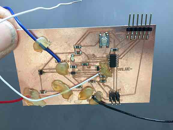
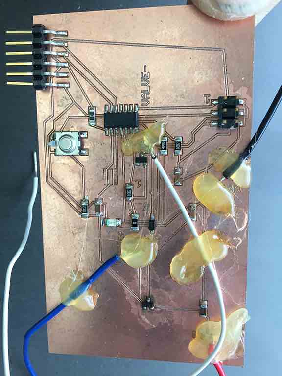
I used flying leads to hook up the solenoid and also the power supply. Notice how the pads are reinforced with hot glue.
(id='fixes')
My instructor, Chris Rohal provided me the helpful hot glue solution. It helps.
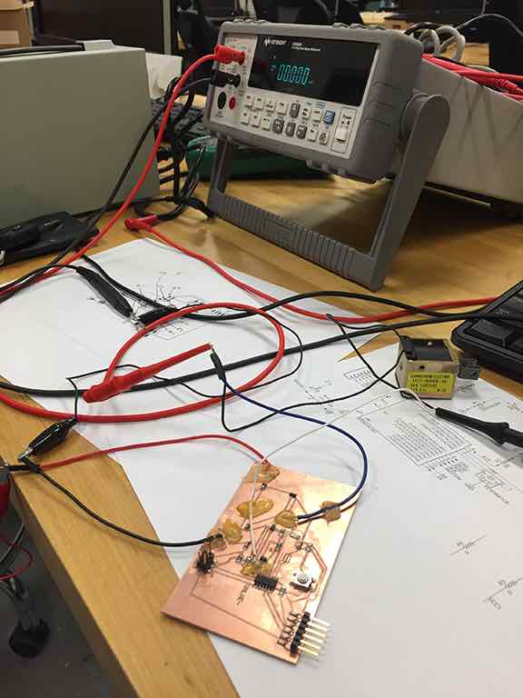
I needed to hook up board to regulated power supply. The voltage regulator on the board failed because I had not removed a powered programmer.
(id='programming')
I programmed the board using an ISP programmer and the Arduino IDE. I needed to add third-party board support to the Arduino IDE. I did this b following the following steps:
You are not done YET! You next must go to Tools - Board - Board Manager and install the package that was just downloaded.
(id='files')
File Arduino IDE Sketch: hello-solenoid-ESP.ino
Here is the listing of the sketch. The program is well documented. I have part of the program commented out for troubleshooting purposes. Notice the declerations for the integers LED, SOLENOID, ESP and BUTTON correspond to significant pinouts mentioned earlier. I have included a module called SoftwareSerial.h which will allow serial communication, anticipating this card will integrate with the final project.
#include <SoftwareSerial.h>

/*
  HELLO-SOLENOID-ESP

  by Paul O'Neill
  Modified from example folder.  Contributing authors noted below.

  Turns on an LED on for one second, then off for one second, repeatedly.

  Most Arduinos have an on-board LED you can control. On the UNO, MEGA and ZERO
  it is attached to digital pin 13, on MKR1000 on pin 6. LED_BUILTIN is set to
  the correct LED pin independent of which board is used.
  If you want to know what pin the on-board LED is connected to on your Arduino model, check
  the Technical Specs of your board  at https://www.arduino.cc/en/Main/Products

  This example code is in the public domain.

  modified 8 May 2014
  by Scott Fitzgerald

  modified 2 Sep 2016
  by Arturo Guadalupi

  modified 8 Sep 2016
  by Colby Newman
*/


const int LED = 7;  //TINY44 PA7
const int SOLENOID = 8;     //TINY44 PB2, IDE 8, pin 5
const int ESP = 2;  //TINY44 PA2, IDE 2, pin 11
const int BUTTON = 10;     //TINY44 button connected to PA3, IDE 3, pin 10


// the setup function runs once when you press reset or power the board
void setup() {
  // initialize digital pin LED_BUILTIN as an output.

  pinMode(LED, OUTPUT);
  pinMode(SOLENOID, OUTPUT);
  pinMode(ESP, INPUT);
  pinMode(BUTTON, INPUT);

//  Serial.begin(9600);
}

// the loop function runs over and over again forever
void loop() {

  int ESPValue=digitalRead(ESP);
//  Serial.println(ESPValue);
  if (ESPValue > 0) {
    delay(1);
    digitalWrite(LED, HIGH);
    //digitalWrite(INPUTLINE, HIGH);
    digitalWrite(SOLENOID, HIGH);
  } else {
     digitalWrite(LED, LOW);    // turn the LED off by making the voltage LOW
     digitalWrite(SOLENOID, LOW);
    /*
    digitalWrite(LED, HIGH);   // turn the LED on (HIGH is the voltage level)
  //  digitalWrite(INPUTLINE, HIGH);
    digitalWrite(SOLENOID, HIGH);
    delay(2500);                       // wait for a second
    digitalWrite(LED, LOW);    // turn the LED off by making the voltage LOW
  //  digitalWrite(INPUTLINE, LOW);
    digitalWrite(SOLENOID, LOW);
    delay(1000);                       // wait for a second
    */
  }
}
Video of the helloOutput board running the hello-world program from an earlier week. Press the button and the LED lights up: https://vimeo.com/264706426
Click here to see HELLO-SOLENOID sketch running the helloOutput board: https://vimeo.com/264706574
(id='power')
Update: I measured the amperage which the solenoid device consumed utilizing the amperage readout on the regulated power supply. The solenoid was drawing 1.3 amps. This inductive load was well withinthe specs of the MOSFET I selected, an IRL520 SOT23, which can handle about 9 amps.