LEARNING OUTCOMES:
This week I continued to build and design around my final project. I explored some ways in which I can communicate from a webpage to my solenoid board through an application. I spiraled between communication and applications in order to test capabilities of my final project. These examples addresses the learning outcomes for this week, Interface and Application Programming, by utilizing the hardware for next week, Networking and Communications. I continued to develop in the Arduino IDE environment with my specialized variation of the Hello-World board we fabricated early on in the course. I also started working with the ESP8266 board which I fabbed as part of Networking week. For me, I co-joined these two weeks together and started spiraling between the two of them. Adding to the spiral, I started researching and experimenting with mods which was developed by Prof. Neil Gershenfeld at the Center for Bits and Atoms at the Massachusetts Institute of Technology in Cambridge, Massachusetts, USA.
(#mods)
During class review during my 2018 student cycle, Neil suggested possibly using MIT MODS as a possible interface for my final project. MODS is a research tool developed at the Center for Bits andAtoms, by Dr. Neil Gershenfeld. It is still under continuous development. Currently, there is scattered documentation which is primarily orientated towards the researchers at MIT-CBA. The goal, according to Prof. Gershenfeld, is for more formal documentation as more community support evolves. For this week, it was necessary for me to download the MIT-MODS repository to my local machine and implemented a local HTTP server which can run MODS locally. I do not have access to the CBA respository, so at this point, download is the only way possible for me. I hope at some point that all FabLabs can have a common repo similar to CBA where we can contribute what we learn and develop to a common repository. Until that happens, I completed my work on my local machine. I have documented the steps needed in order to do this on a MacNotebook at the end of this page. (#mods).
In order to communicate with an embedded device, you must get the module called WebSerialServer working. I developed a toolchain for both my Mac running Xcode and a Windows 10 Laptop running WSL (Windows Subsystem for Linux) with Ubuntu. I programmed an Arduino with a program which generates a list of numbers from 1 to 100 and back to 1 continuously as a troubleshooting test tool to verify the connectivity between laptop and embedded device. Now that I have built my toolchains, my next future goal is to develop an interface for my final project in Embedded-MODS.
I took a ton of screenshots, enough to do a stroke-by-stroke tutorial. With Fabacademy, I am nearing my 300MB space limit, so I will have to make a tutorial a side project. Getting mods to communicate with a board requires a lot of trial and error. Using an Arduino gives me a good, reliable, starting point to troubleshoot my toolchain before I begin development.
First, I wrote a program called "HELLO-SOLENOID-ESP" which allows my solenoid board to listen to the sensor board and throw a solenoid valve on and off. I next wrote a program called "esp8266-webserver-graphical-lumionox-o2-solenoid-test" which runs as a webserver, which generates a webpage which allows the client to press one of two buttons.
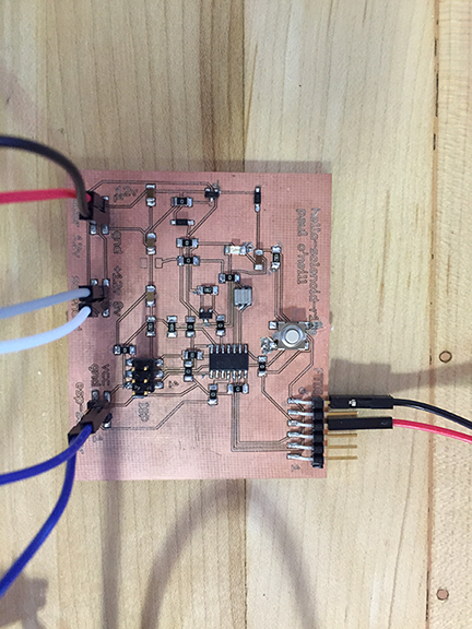
I adapted this program from one of the example sketches included with the Arduino IDE for my hello-solenopid-r13 board. I added the solenoid to act in parallel to the LED. This board is based on the ATMEL ATTiny44 which is 5 volt based. The solenoid valve is 12 volts. In previos boards, I cooked the voltage regulator because the board was being powered from two sources, which "goofed" up the voltage regulator and caused it to fail. I added diodes to protect the voltage regulator. Nevertheless, I use a programmer which has the ability to power or not power the board. I had good success with the "Sparkfun AVR pocket programmer" available through Digikey, part number 1568-1080-ND for $14.95. I highly recommend it. It is convenient to leave power off and keep debuigging your board without having to worry about frying a voltage regulator.
---------------------------------------------------------------------------------------------------------------
#include <SoftwareSerial.h>
/*
Blink
Turns on an LED on for one second, then off for one second, repeatedly.
Most Arduinos have an on-board LED you can control. On the UNO, MEGA and ZERO
it is attached to digital pin 13, on MKR1000 on pin 6. LED_BUILTIN is set to
the correct LED pin independent of which board is used.
If you want to know what pin the on-board LED is connected to on your Arduino model, check
the Technical Specs of your board at https://www.arduino.cc/en/Main/Products
This example code is in the public domain.
modified 8 May 2014
by Scott Fitzgerald
modified 2 Sep 2016
by Arturo Guadalupi
modified 8 Sep 2016
by Colby Newman
*/
const int LED = 7; //TINY44 PA7
const int SOLENOID = 8; //TINY44 PB2, IDE 8, pin 5
const int ESP = 2; //TINY44 PA2, IDE 2, pin 11
const int BUTTON = 10; //TINY44 button connected to PA3, IDE 3, pin 10
// the setup function runs once when you press reset or power the board
void setup() {
// initialize digital pin LED_BUILTIN as an output.
pinMode(LED, OUTPUT);
pinMode(SOLENOID, OUTPUT);
pinMode(ESP, INPUT);
pinMode(BUTTON, INPUT);
// Serial.begin(9600);
}
// the loop function runs over and over again forever
void loop() {
int ESPValue=digitalRead(ESP);
// Serial.println(ESPValue);
if (ESPValue > 0) {
delay(1);
digitalWrite(LED, HIGH);
//digitalWrite(INPUTLINE, HIGH);
digitalWrite(SOLENOID, HIGH);
} else {
digitalWrite(LED, LOW); // turn the LED off by making the voltage LOW
digitalWrite(SOLENOID, LOW);
/*
digitalWrite(LED, HIGH); // turn the LED on (HIGH is the voltage level)
// digitalWrite(INPUTLINE, HIGH);
digitalWrite(SOLENOID, HIGH);
delay(2500); // wait for a second
digitalWrite(LED, LOW); // turn the LED off by making the voltage LOW
// digitalWrite(INPUTLINE, LOW);
digitalWrite(SOLENOID, LOW);
delay(1000); // wait for a second
*/
}
}
---------------------------------------------------------------------------------------------------------------
(id='code')
(id='gui')
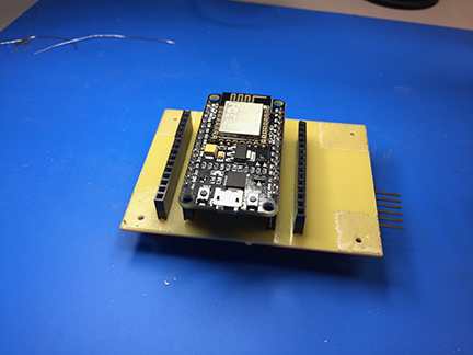
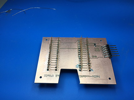
I wrote this program to demonstrate an application program that runs on the internet and controls the hello-nodeMCU board, which yet controls the solenoid board. The hardest part here is mapping out physical pins to GPIO pins on the ESP8266. This is why I made a shield with a couple of extra headers, so I could move jumper wires around until I found the GPIO that works. The comments in the program explains mapping between the Arduino IDE and the module I used.
---------------------------------------------------------------------------------------------------------------
/*
ESP8266 Server program to read Luminox O2 sensor.
By: Paul O'Neill
(C) Copyright Paul X. O'Neill, All rights reserved.
Receives from software serial port, sends to hardware serial port.
* RX is digital pin 10 (connect to TX of level shifter: pin B1)
* TX is digital pin 11 (connect to RX of level shifter: pin B2)
The code was written for hello-nodeMCU and Arduino IDE ver. 1.6.1.
*/
#include <ESP8266WiFi.h>
#include <ESP8266WebServer.h>
const char* ssid = "backbarn";
const char* password = "fabacademy";
String form = "<form action='led'><input type='radio' name='state' value='0' checked>On<input type='radio' name='state' value='1'>Off<input type='submit' value='Submit'></form>";
String imagepage = "<img src='/led.png'>";
// This is a png file (led.png)
const char image[] = {
0x89, 0x50, 0x4e, 0x47, 0x0d, 0x0a, 0x1a, 0x0a, 0x00, 0x00, 0x00, 0x0d, 0x49, 0x48, 0x44, 0x52,
0x00, 0x00, 0x00, 0x10, 0x00, 0x00, 0x00, 0x10, 0x08, 0x02, 0x00, 0x00, 0x00, 0x90, 0x91, 0x68,
0x36, 0x00, 0x00, 0x00, 0x01, 0x73, 0x52, 0x47, 0x42, 0x00, 0xae, 0xce, 0x1c, 0xe9, 0x00, 0x00,
0x00, 0x04, 0x67, 0x41, 0x4d, 0x41, 0x00, 0x00, 0xb1, 0x8f, 0x0b, 0xfc, 0x61, 0x05, 0x00, 0x00,
0x00, 0x20, 0x63, 0x48, 0x52, 0x4d, 0x00, 0x00, 0x7a, 0x26, 0x00, 0x00, 0x80, 0x84, 0x00, 0x00,
0xfa, 0x00, 0x00, 0x00, 0x80, 0xe8, 0x00, 0x00, 0x75, 0x30, 0x00, 0x00, 0xea, 0x60, 0x00, 0x00,
0x3a, 0x98, 0x00, 0x00, 0x17, 0x70, 0x9c, 0xba, 0x51, 0x3c, 0x00, 0x00, 0x00, 0x18, 0x74, 0x45,
0x58, 0x74, 0x53, 0x6f, 0x66, 0x74, 0x77, 0x61, 0x72, 0x65, 0x00, 0x50, 0x61, 0x69, 0x6e, 0x74,
0x2e, 0x4e, 0x45, 0x54, 0x20, 0x76, 0x33, 0x2e, 0x33, 0x36, 0xa9, 0xe7, 0xe2, 0x25, 0x00, 0x00,
0x00, 0x57, 0x49, 0x44, 0x41, 0x54, 0x38, 0x4f, 0x95, 0x52, 0x5b, 0x0a, 0x00, 0x30, 0x08, 0x6a,
0xf7, 0x3f, 0xf4, 0x1e, 0x14, 0x4d, 0x6a, 0x30, 0x8d, 0x7d, 0x0d, 0x45, 0x2d, 0x87, 0xd9, 0x34,
0x71, 0x36, 0x41, 0x7a, 0x81, 0x76, 0x95, 0xc2, 0xec, 0x3f, 0xc7, 0x8e, 0x83, 0x72, 0x90, 0x43,
0x11, 0x10, 0xc4, 0x12, 0x50, 0xb6, 0xc7, 0xab, 0x96, 0xd0, 0xdb, 0x5b, 0x41, 0x5c, 0x6a, 0x0b,
0xfd, 0x57, 0x28, 0x5b, 0xc2, 0xfd, 0xb2, 0xa1, 0x33, 0x28, 0x45, 0xd0, 0xee, 0x20, 0x5c, 0x9a,
0xaf, 0x93, 0xd6, 0xbc, 0xdb, 0x25, 0x56, 0x61, 0x01, 0x17, 0x12, 0xae, 0x53, 0x3e, 0x66, 0x32,
0xba, 0x00, 0x00, 0x00, 0x00, 0x49, 0x45, 0x4e, 0x44, 0xae, 0x42, 0x60, 0x82
};
// HTTP server will listen at port 80
ESP8266WebServer server(80);
const int solenoid = 16; //ESP-12 pin1, D0, GPIO 16
const int led = 4; //ESP-12 pin3, D2, GPIO 4
void handle_adc() {
float val = analogRead(0);
server.send(200, "text/plain", String(val));
}
void handle_led() {
// get the value of request argument "state" and convert it to an int
int state = server.arg("state").toInt();
digitalWrite(led, state);
digitalWrite(solenoid, state);
server.send(200, "text/plain", String("LED is now ") + ((state)?"off":"on"));
}
void handle_image() {
server.send(200, "image/png", "");
WiFiClient client = server.client();
client.write(image, sizeof(image));
}
void handle_webpage_with_image() {
server.send(200, "text/html", imagepage);
}
void setup(void) {
Serial.begin(9600);
Serial.println("");
pinMode(led, OUTPUT);
pinMode(solenoid, OUTPUT);
// Connect to WiFi network
WiFi.begin(ssid, password);
// Wait for connection
while (WiFi.status() != WL_CONNECTED) {
delay(500);
Serial.print("-SOLENOID TEST-");
digitalWrite(solenoid, HIGH); // turn the SOLENOID on (HIGH is the voltage level)
delay(1000); // wait for a second
digitalWrite(solenoid, LOW); // turn the SOLENOID off by making the voltage LOW
delay(1000); // wait for a second
digitalWrite(solenoid, HIGH); // turn the SOLENOID on (HIGH is the voltage level)
delay(1000); // wait for a second
digitalWrite(solenoid, LOW); // turn the SOLENOID off by making the voltage LOW
delay(1000); // wait for a second
digitalWrite(solenoid, HIGH); // turn the SOLENOID on (HIGH is the voltage level)
delay(1000); // wait for a second
digitalWrite(solenoid, LOW); // turn the SOLENOID off by making the voltage LOW
delay(1000); // wait for a second
}
Serial.println("");
Serial.print("Connected to ");
Serial.println(ssid);
Serial.print("IP address: ");
Serial.println(WiFi.localIP());
// Set up the endpoints for HTTP server
//
// Endpoints can be written as inline functions:
server.on("/", [](){
server.send(200, "text/html", form);
});
// And as regular external functions:
server.on("/adc", handle_adc);
server.on("/led", handle_led);
server.on("/led.png", handle_image);
server.on("/showled", handle_webpage_with_image);
// Start the server
server.begin();
Serial.println("HTTP server started");
}
void loop(void) {
// check for incomming client connections frequently in the main loop:
server.handleClient();
}
---------------------------------------------------------------------------------------------------------------
(id='process')
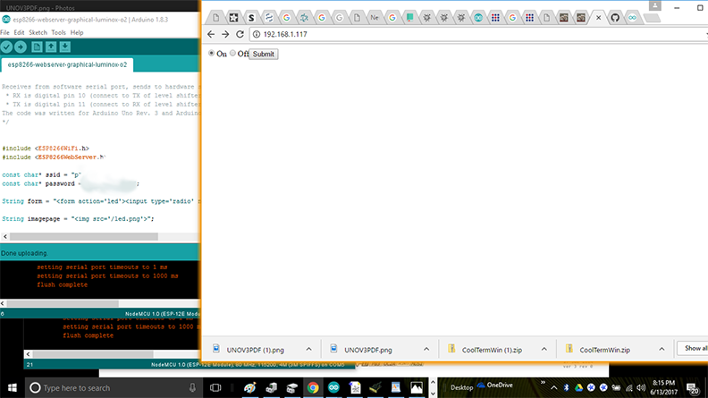
Screenshot of client page. The server is located at local IP address 192.168.1.117 and the solenoid is ion the ON state.
(id='problems')

I have a neighbor who I believe has added a linear amplifier to his router. It is creating havoc with my 2.4GHz Wifi system. I utilize a Ubiquiti Unifi Distributed Managed Mesh Network at the farm. With the distributed mesh network, I can analyse to some degree the source of the interference. Unfortunately, with the ESP8266, it is only available with the 2.4GHz frequencies. The 5GHz Wifi frequencies have less issue with collisions and interference.Later this past fall, I installed wire lathe and cementious stucco to the outside of my barn. This makes it very hard for radio energy to pass inside to the barn. This has mitigated some of the collission issues with the ESP8266 module. Another possible solutuion may be to use a module which utilizes the 802.15 system, namely an XBee module.
(id='mods')
For the 2018 cycle, Professor Neil Gershenfeld suggested I should try mods to interface to my final project. I figured I would start ahead of time, prior to Neil's lecture on the subject. First I would start by exploring mods by reviewing some of the presentations given by Neil.
Mods is a program generator, authored by Dr.Neil Gershenfeld of the Center for Bits and Atoms at the Massachusetts Institute of Technology. Mods produces javascript programs via a graphical user environment wherein you select nodes and graphically link them together. The documentation available is a README.md file within the repository, which I explain later.
I first tried to access MODS with my iPhone, but you need to right-click or double-click to initiate development. Since I cannot right-click with my phone, you cannot edit a mod "page". So, as a requirement to use mods, you need a two-button mouse. Once I got back to the Chrome browser on my MacBook, I was able to start exploring with my two-button mouse. I inquired to the author about documentation, and I received a prompt response as follows: "it's a research tool that's still under continuous development; documentation will come as it evolves into community support." Program generators allow quick/fast generation of code which can later be used as the basis of a more refined application. The resultant code of mods is Javascript. I do not know javascript, and I am not much of a coder. However, I have coded many years ago in a variety of what are considered legacy languages. I have embedded myself into Fabacademy to learn, so here we go.
The platform I am using is a MacBook Pro with Xcode installed, git working, two-button mouse, Chrome web-browser, and Adobe Dreamweaver editing application. You could substitute the Mac with a Linux machine. I would think that Windows10 with Ubuntu updates may work as well.
I researched for documentation. I couldn't find any. I then searched for video. I found something to start with: http://academy.cba.mit.edu/classes/input_devices/mag/hello.mag.45.mods.mp4
I shared the video with my instructor, Scott Zitek, and I proposed to Scott that I would be interfacing the Oxygen sensor in my final project, which communicates serially, with MODS in a fashion similar to what was shownin the video. Scott then tried re-creating what was shown in the video and was impressed how simple MODS is. I did the same.
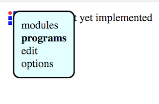
Once I wrote a MOD, I needed to figure how to save my work. I first tried RIGHT-CLICK, OPTIONS, SAVE-FILES, and MODS promptly brought me to the MIT CBA repository.
Since I don't have a LOGIN for that repository, I had to figure something else out, perhaps saving locally. The next thing I tried was PROGRAMS-SAVE LOCAL PAGE. You will get these bubbles which pop out of the CBA icon in the top left of the page, as shown:
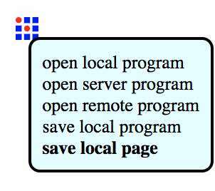
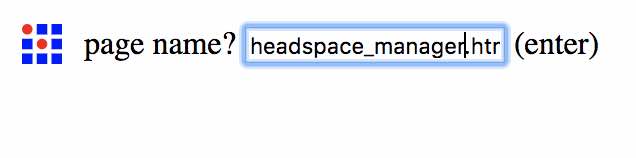
You enter the name you would like, and you get driven back to the "File-Save" idiom on your local machine. In my case, a Mac.
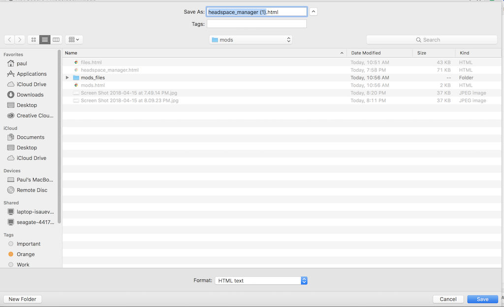
This program saves as an HTML file to my local drive. This file can now be saved to my Fabacademy repo,and retrieved here:
My instructor, Scott Zitek came up with this clever program which animates the "bar graph" node with an infinite loop by cross linking a "step and delay" node with a "delay event" node.
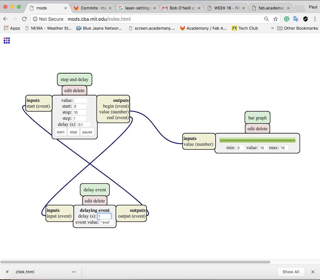
You can run this mod by loading this webpage:
Program: zitek.html
I did notice that the zitek.html file will not reload, whereas the headspace_manager.html does. I next viewed the files in developer mode (more-tools, developer-tools).
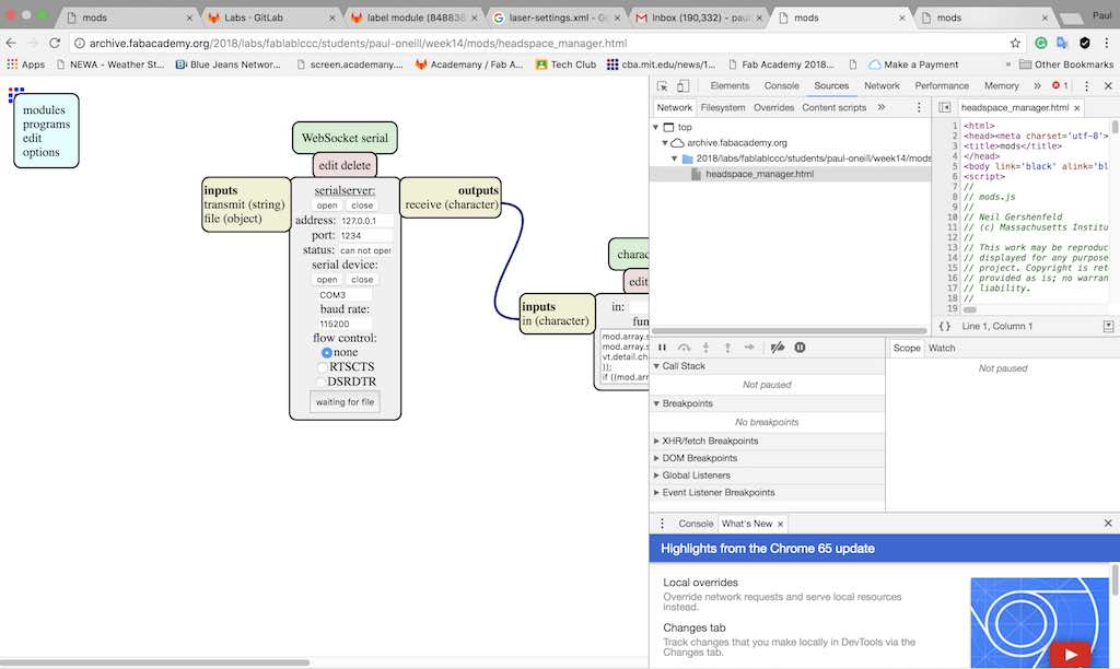
The file named headspace_manager loads fine. It includes Javascript modules by Neil Gershenfeld.
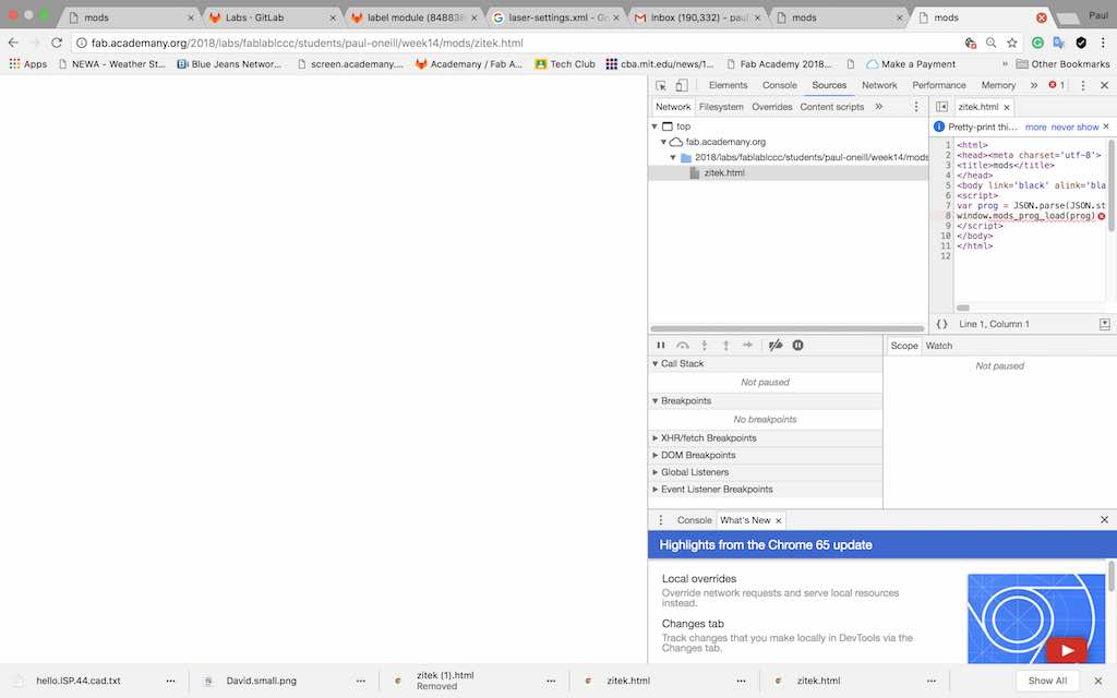
The file called zitek does not load correctly. Big blank page. Looking further with developer tools, when I fly my mouse curser over the red-x-button, I get a popup error message as shown:
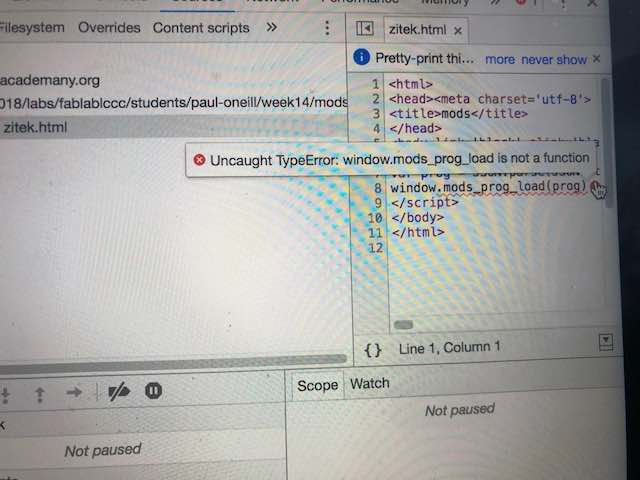
Did I do something wrong?
I try again, from scratch, sketching out the zitek file, nd save it in two different ways,to see what happens. I also make sure the file isn't running the infinite loop.
I first tried saving as a programs-page, by drilling through the following menu: right-click, programs, save-local-page and enter zitek2.html. RELOAD IS GOOD!
I next tried saving as a programs-program, by drilling through the following menu: right-click, programs, save-local-program and enter zitek3.html. RELOAD NO-GOOD.
I have not recreated the original error though. I tried the right-click, programs, save-local-page sequence while the infinite-loop is running. My page does not save correctly while the loop is running. I would like to investigate the index.html page served from http://mods.cba.mit.edu/ further. This page is the main routine for mods, which is a program generator which generates javascript. There is a section in the index.html file, starting at line 237, which is a menu selection used to save files:
// save local page
//
add_menu(div,'save local page',function(evt){
document.body.removeChild(evt.target.parentNode)
mods.globals.menu = null
save_page()
})
document.body.appendChild(div)
}
//
Further down in index.html, line 559,there is a section of code as follows:
function save_page() {
set_prompt('page name? ')
get_prompt(mods.ui.progname+".html",function(filename){
mods.ui.progname = filename
var prog = {modules:{},links:[]}
var modules = document.getElementById('modules')
//
// save modules
//
for (var c = 0; c < modules.childNodes.length; ++c) {
var module = modules.childNodes[c]
var idnumber = module.id
prog.modules[idnumber] = {
definition:module.dataset.definition,
top:module.dataset.top,
left:module.dataset.left,
inputs:{},
outputs:{}
}
}
//
// save links
This code asks the user to enter a name to use to save their mod to their local machine. Further along in this section, there is more code which I believe copies what is in the users workspace. I think an easy fix would to be to set a global variable upon initialization of a page which keeps track of the "state" of the mod, such as "STOPPED". When the user presses a "start" button, the state is changed to "RUNNING". When the user initiates a save, don't allow the save until the user stops the script. Even simpler would just to display a warning to the user to make sure all running scripts are stopped.
Right now, this routine probably gets screwed up by a script which is already running. Perhaps that may be why zitek.html is incomplete. I don't want to invest time unless I know that I can save my work. I know now that I cannot have a loop running while I try to save a file. If I do,my file will be screwed up. Not a big deal. Easy to workaround.
Within mods isa file called files.html. This list is an indented outline of the entire contents of mods that are available. Some of the contents contains program scripts, some contains data, some contain script-functions.
The main catagories in the files.html (some description taken from README.md) are listed below. I have noted some items with ??? wherever I cannot reference the README.md with the actual repository contents.
Within the mods repo, the README.md file contains useful information about the mods project, current problems, workarounds.
I did explore a server program called "math expressions". After loading that program to my page, I noticed the page had somenodes called "math expression" which are not available in the modules-open server module menu. I was able to access "math expression" module if I followed a couple of steps. First,I pressed the edit button on the module. I get a page showing it's javascript code. Next,I save the code to a local directory. After that, I can access that module by following the menu modules-open local modules, and drilled down to my local directory where I saved it.
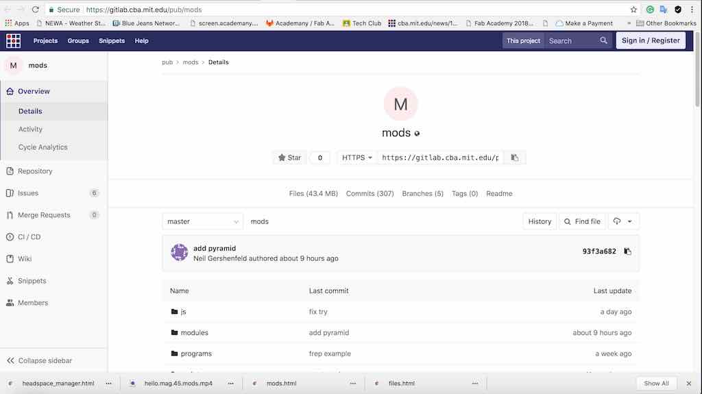
A repository resource I found at CBA for mods: https://gitlab.cba.mit.edu/pub/mods
I gleened the following help:
To install and run mods locally
You need to first install node.js.
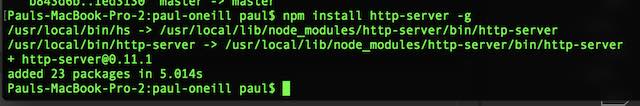
Install the http-server npm package. Including '-g' sets the installs the package gloabally, allowing you to use it as a command line tool:
npm install http-server -g
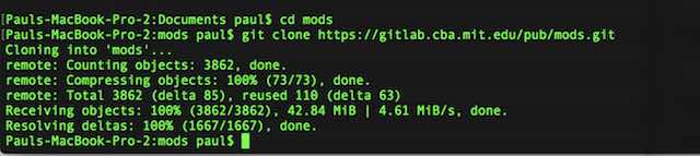
Clone the mods repository:
git clone ssh://git@gitlab.cba.mit.edu:846/pub/mods.git
Use the command line to navigate to the root of the mods repository:
cd mods
Start up a server:
http-server
Open a browser tab and go to 127.0.0.1:8080 which is the same as http://localhost:8080 to view the server that you just started.
Depending on how to need to use mods you can start local servers located in mods/js, for example, if you start from the root of the mods repository:
cd js
node printserver.js
Mods Connection Debugging
set correct serial port permission (do this each time you reboot the machine): chmod a+rwx /dev/ttyUSB0
start serialserver in the terminal so you can see the logs as it tries to connect. navigate to the mods/js folder in the terminal (probably use cd ~/mods/js) and type: node serialserver.js ::ffff:127.0.0.1 1234
check serialserver is running with: ps aux | grep node
Prerequisites to installing Node.js and NPM: Xcode and Brew must be installed. I have already donethis earlier, so I continue to the next step:

Next, I use npm to install a http server by typing npm install http-server -g
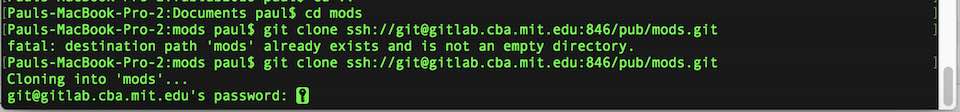
Next, I make sure I am notin the directory I use for Fabacademy. I switch to my Documents directory and create a folder called mods. I use the following command: git clone ssh://git@gitlab.cba.mit.edu:846/pub/mods.git
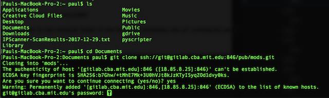
The repo asks me for a password. I don't have one. Back to the drawing board. Why not just clone the repo into a local directory. I don't have keys to the repo, but this should allow me to get updates easily as they are made, and I should have the entire mods set right on my laptop.
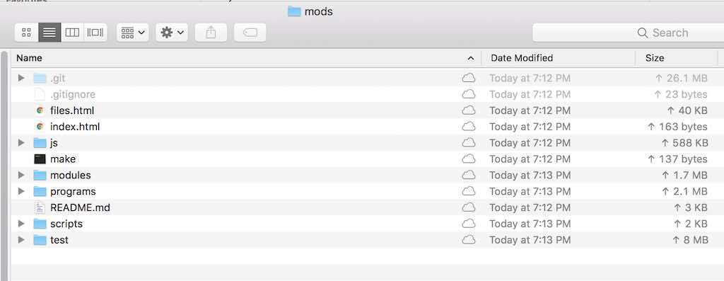
Checking my directory, I find all the files there.
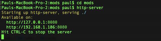
Next, I start up a server by typing http-server
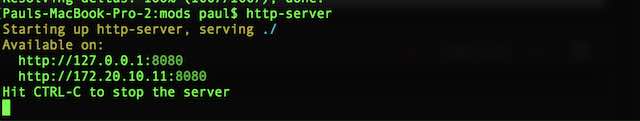
It appears to work. Next, I will try to access my local mods servcr with my browser. I enter the following address: http://localhost:8080/mods
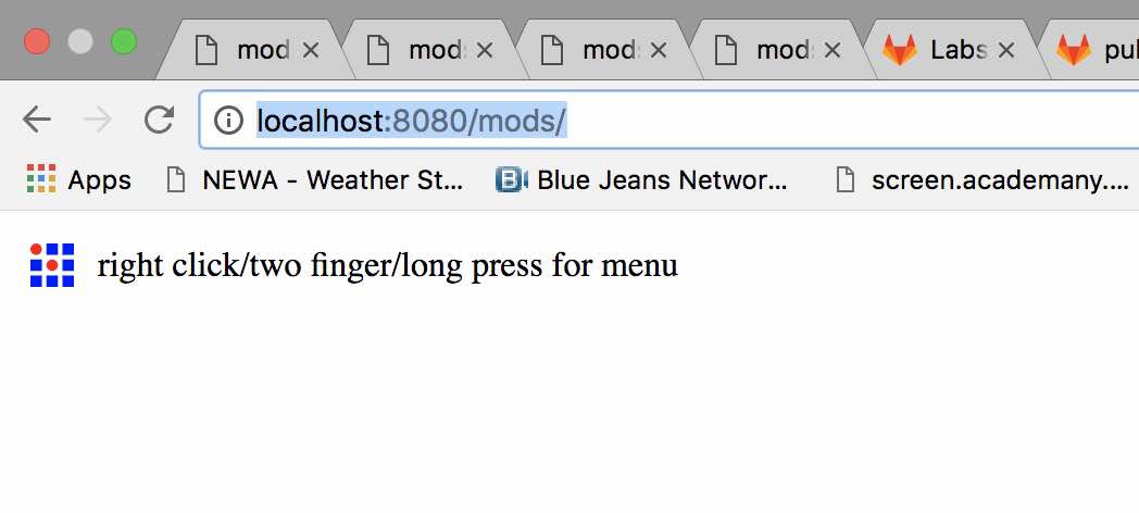
It worked. Next, I will need to explore how to access physical ports via serial.
I figured I would first try to solve identifying the serial port on my Mac. This was an issue when I did the MtM group project. I am more familiar with the Windows environment, and identifying and assignment of serial ports is simple for me... COM1, COM2, COM3 and so forth.I do not have access to the CBA repo, so at this point I am thinking of continuing running a MODS server on my Mac as my development environment. However, I need to tackle the serial port issue.
My next plan of attack is to work wioth something I know works somewhere else. I fiugure I would start with a common reference board, the Arduino Uno. I plug it into a USB-C port witha USB to USB-C adapter on my MacBook Pro. I run the Arduino IDE, and it has a hard time findiong the COM port. If I use my Sparkfun toolchain, I can program the Arduino without difficulty. I next research COM ports on Macbook and Arduino, and I discover I am not alone. I decided to try a utility called USB Probe. It can be found on ther Apple Developer page, which you can access here: https://developer.apple.com/downloads/index.action
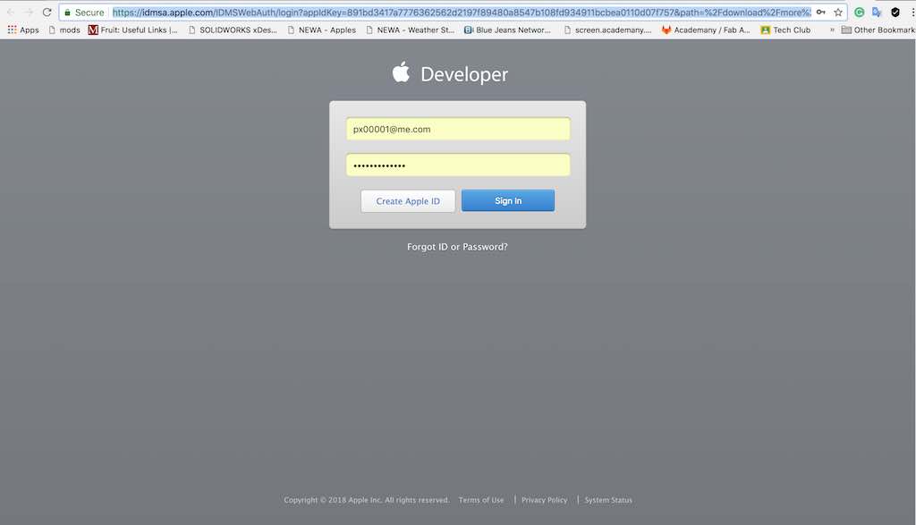
I next put in my Apple ID and password.
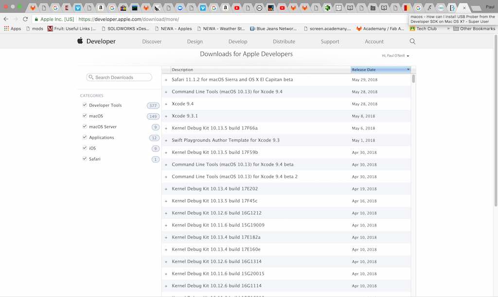
I next get a nice list of utilities which I never knew existed. I am looking for a utility called "IOUSB Family Log"
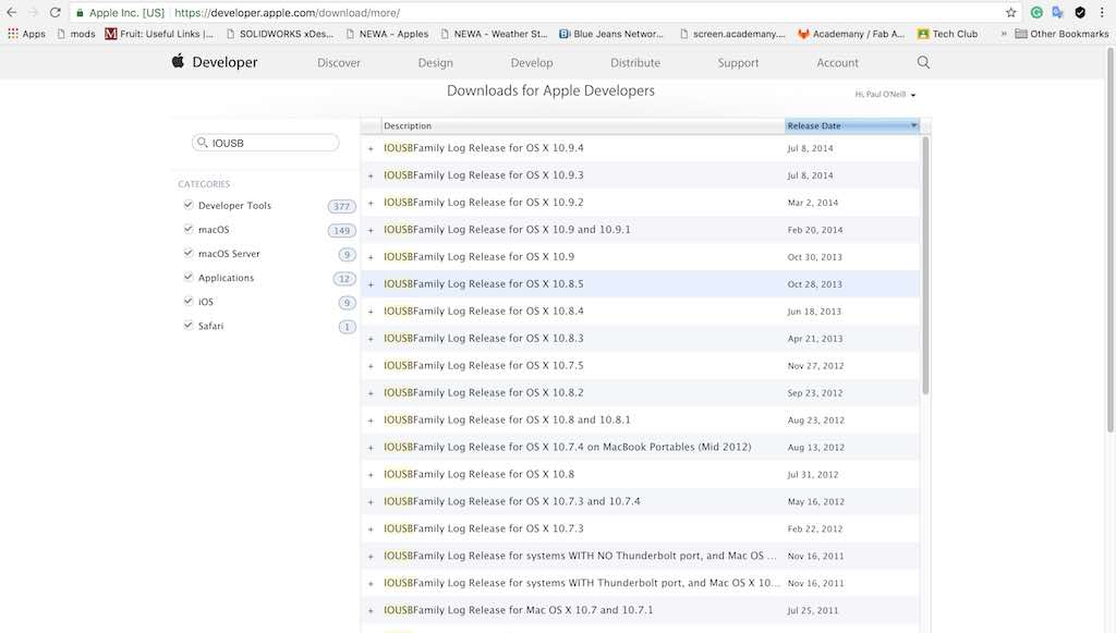
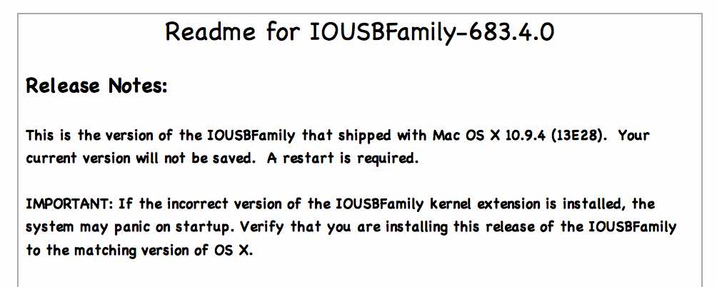
I proceed to download the latest version which was released July of 2014. An ionteresting pull-down message appears:
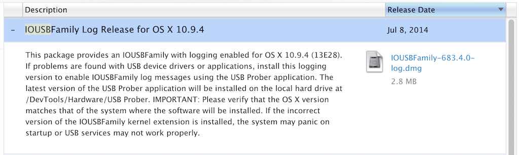
The message is not very encouraging. I decide to give it a go anyway. The download proceeds smoothly. I get an error message that the app is from an unidentified developer,
IOUSBFamily-683.4.0.pkg” can’t be opened because it is from an unidentified developer. developer.apple.com
That's strange. I will have to override that. I check out the README file that comes with the package:
My version of OS X is macOS High Sierra Version 10.13.4. Not quite sure what to do at this point. I don't want to kill my system, so I explore further. I find some references to an application called Wireshark. I read more about it here: https://wiki.wireshark.org/CaptureSetup/USB
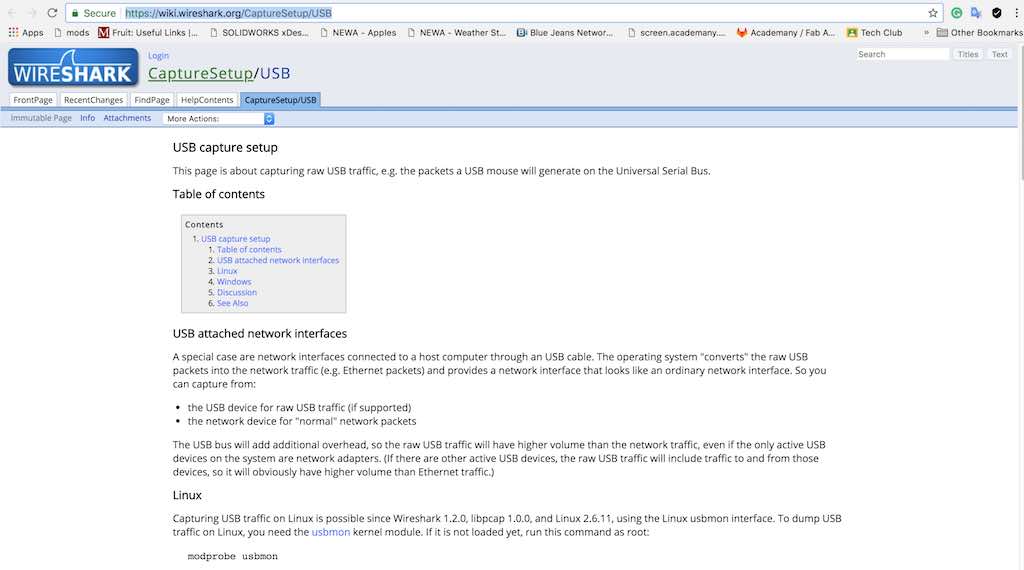
This app looks like it is just for Linux and Windows. I then explore the Apple Developer Forum for an app called IORegistryExplorer:
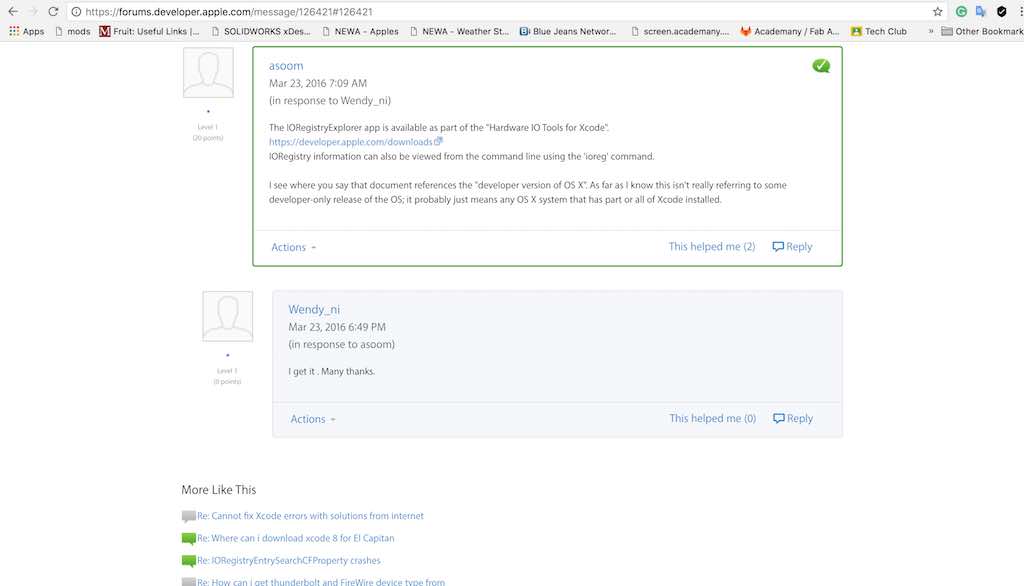
The message says it can be loaded from a command line with the command "ioreg". I try the command and it sort of works. It gives me a big dump of data that I really don't understand. Not exactly what I was looking for. I next go back to developer.apple.com/download/more and search for "Hardware IO Tools". I get the following screen whoich looks promising:
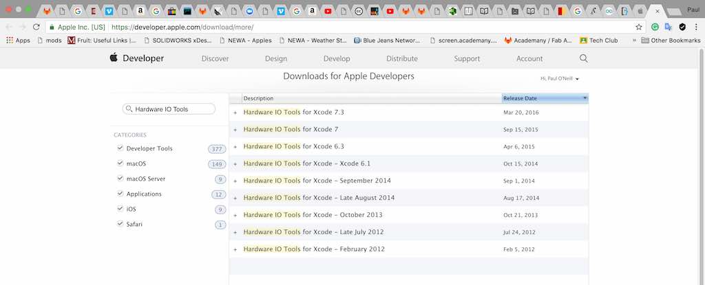
I click on the latest version and I get the following dropdown message:
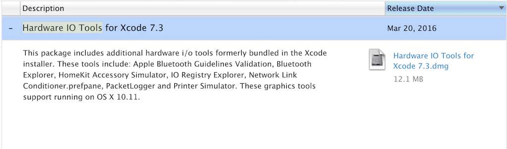
I proceed to download this package. Another screen pops up.
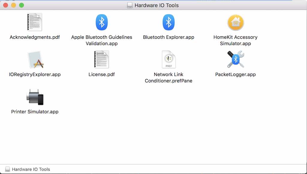
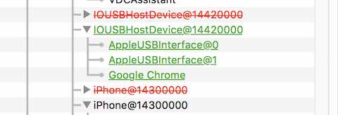
At first glance, it looks like it applies mostly to bluetooth and printers. I drill into the IORegistryExplorer app. I'm looking for USB. I explore, pulling up portions of the tree I don't need. I come upon a section which looks like USB. I unplug my daughters iPhone and plug my iPhone in. I can see the devices being disconnected (red) and connected (green shifts to black).
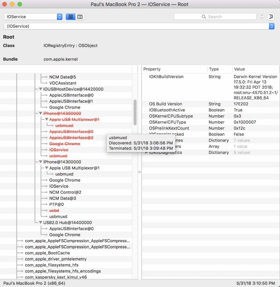
Pretty promising. Now lets see what happens when I plug and unplug microcontrollers and toolchains.
The Arduino Uno shows up as this:
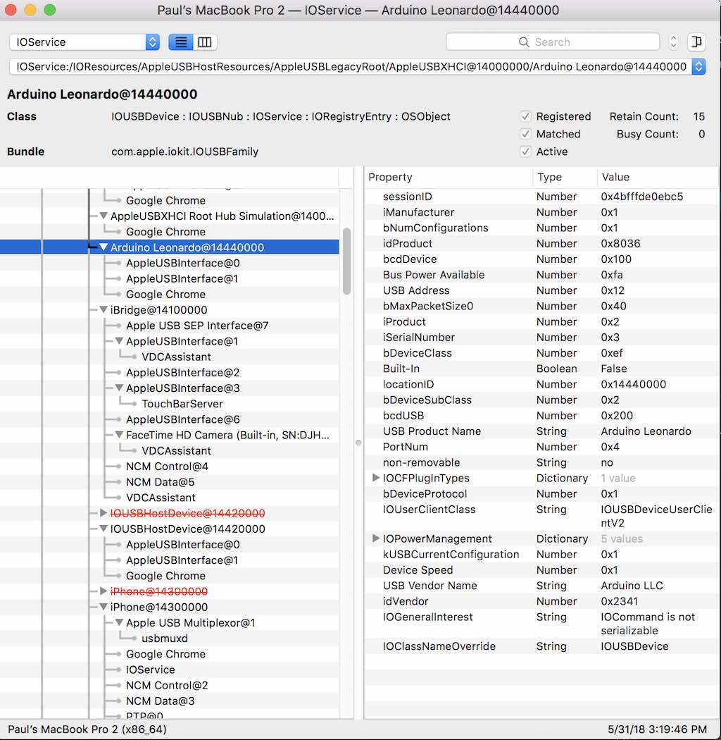
Now I plug in an Arduino Leonardo next to it.
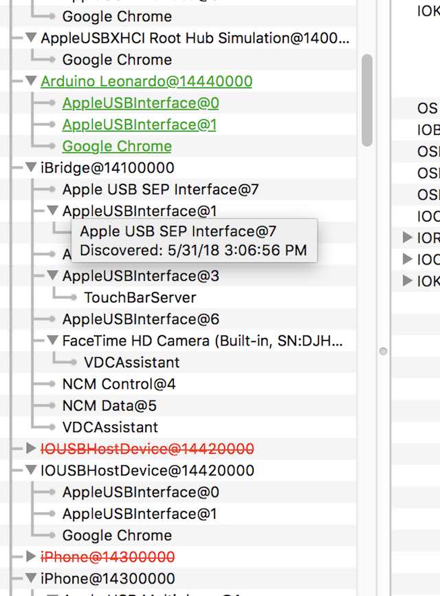
Both boards are pliugged in. The Arduino Leonardo shows itself in GREEN and the Arduino Uno has shifted to plain BLACK. I click on the Arduino Leonardo listing and get all of it's details on the right panel. It's port number is "0x4".
Same thing for the Arduiono Uno. It's port number is "0x2".
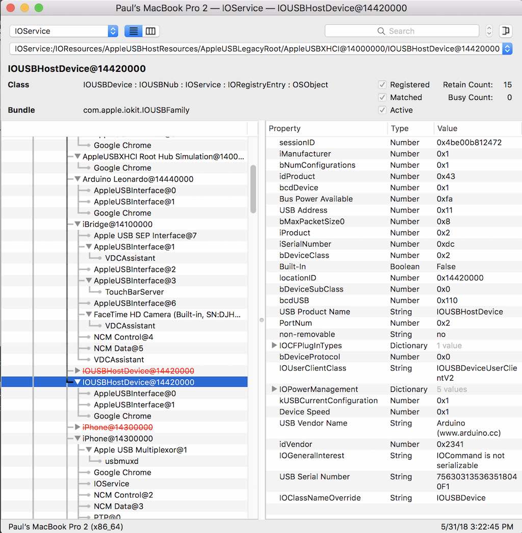
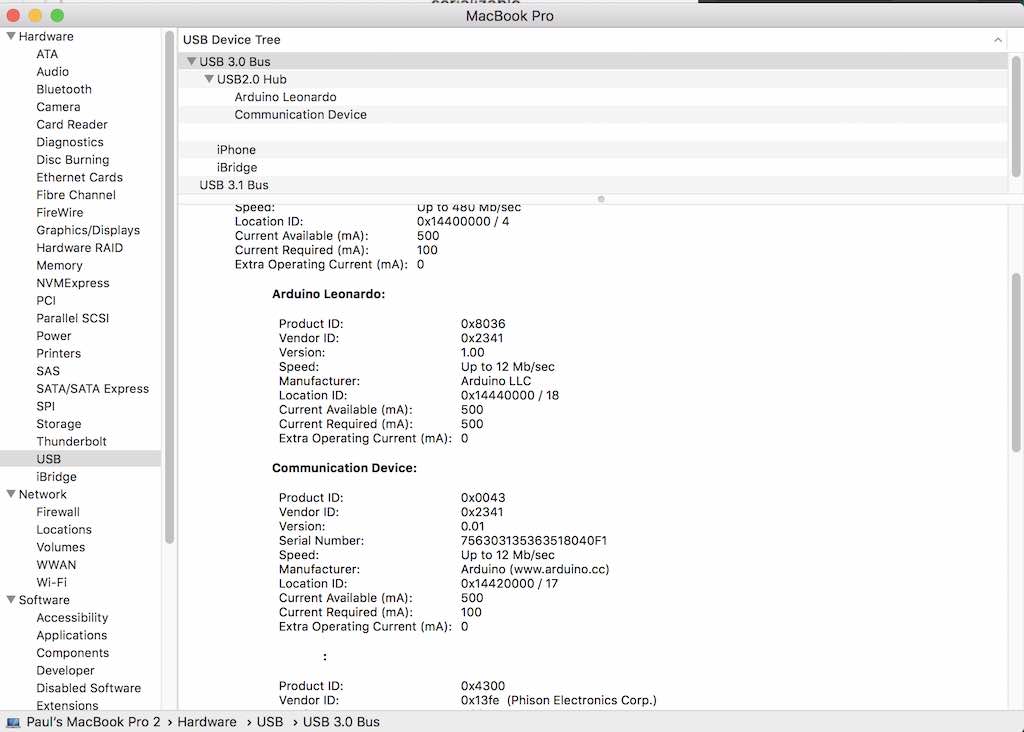
I check my MacBook system information. The Arduino Leonardo is very obvious. The Arduino Uno ("Communication Device") is showing, but not so obvious.You can tell it is Arduino by looking at the line which describes the Manufacturer.
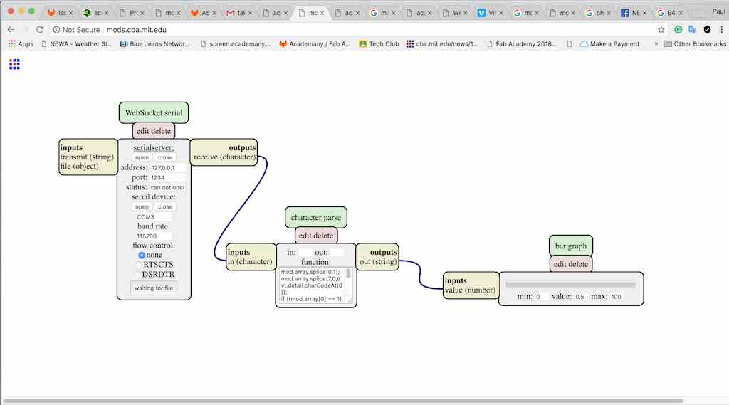
Ok, the Arduino is registering with my USB port as a tty (Teletype) port. At this point, I want to set up my Arduino as a test device for serial connection. I craft a sketch which will infinitely loop forever and generate numbers increasing from 1 to 100, and then decrease from 100 to 1, and repeat forever. I am hoping I can send this data to the ui feature of mods called "bar graph." Not being familiar with mods, I want to simplify my troubleshooting as much as possible.
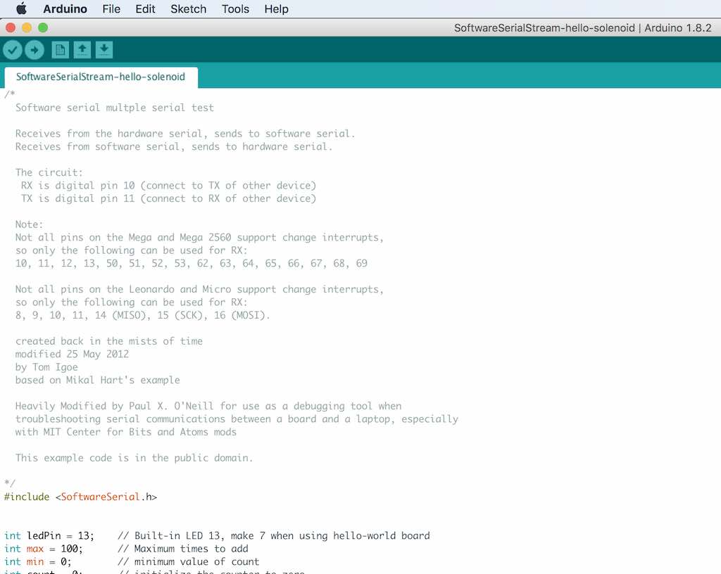
I create the sketch with the Arduino IDE environment on both my Mac and my Windows 10 laptop. Either way, it is good. However, the nomenclature of the serial ports vary between machines. With the Mac, the Arduino shows up as /dev/tty.usbmodem1441, and sometimes as /dev/tty.usbmodem1461. It can vary depending on what you have plugged into your laptop. On the Windows machine, from Device manager, it will numerate with the MS-DOS designation of COM4 or COM6, and with the WSL/Ubuntu Terminal, looks like /dev/ttyS4. I start by modifying one of the example programs that comes with the Arduino IDE package, "SoftwareSerialStream" and heavily modify it. My plan is to have a LED on the board to blink while the program pushes the number series 1..100 and then 100..1 within an infinite loop. Many lines which I used for debugging, I comment out, so you can follow my workflow in writing the program. The library SoftwareSerial is included and allows the program to access UART hardware. LED PIN value can be changed from 13 (Uno, Leonardo) or 7 (hello-world).
The interger variables min and max define the series range of numbers to generate.
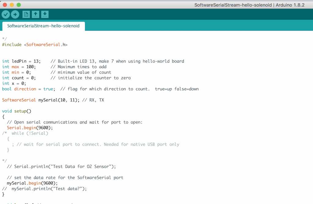
Open the serial port at 9600 baud (speed). I use a lot of print statements when I write programs. They are shown commented out (greyed out).
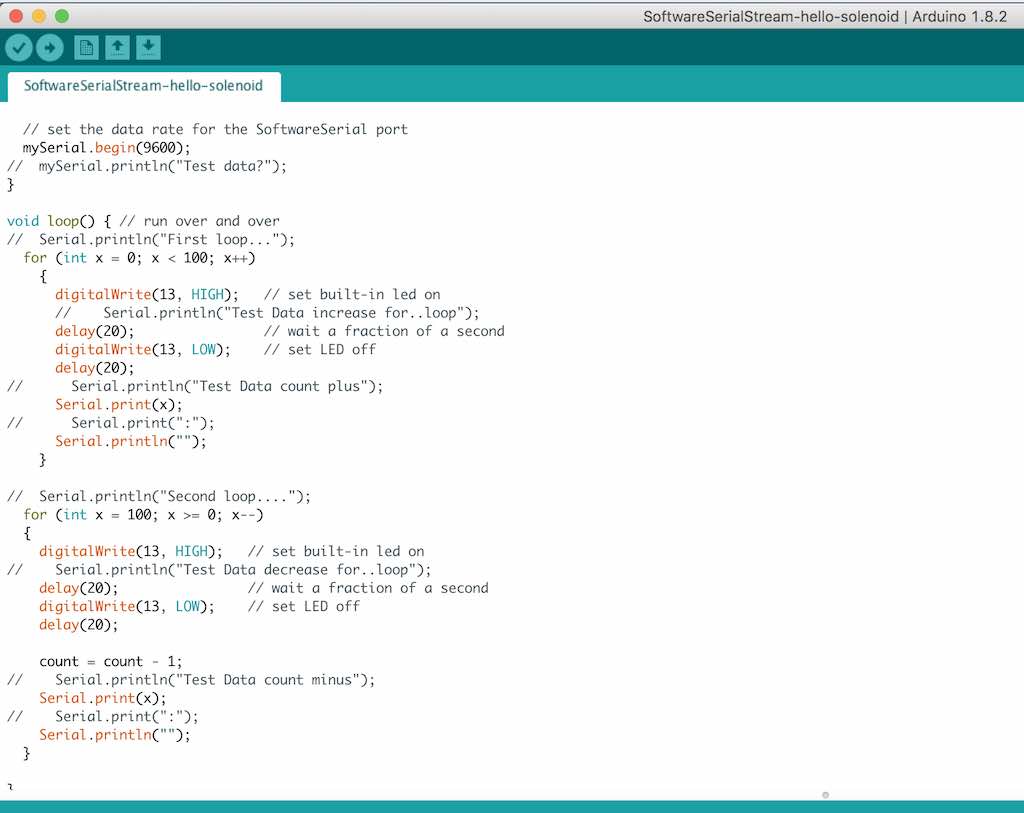
The main loop is here. Prints a number and a Carriage return/line feed. I think this is what CBA mods is expecting. I can only guess right now.... As I print a number to the serial port, blink a LED so I know the board is trying to do something.
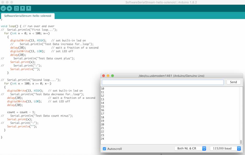
Movie which shows the above sketch generating numbers and observed with the serial monitor. https://vimeo.com/273536398
Ok, time to spiral to MODS. I try to get an update on MODS. Darn, no password.....
I'll just use my old version for now. Start up the server:
Point my browser to the IP address above, or type http://localhost:8080:
I tried running Chrome web browser and typed the address 127.0.0.1:8080. I got the CBA logo. However, WebSerialServer would not work. I spent hours and hours trying to figure this out. I explored the repo at CBA, explored the student work at CBA, and gleened some important information. First, most web browsers and Anti-virus/malware programs close a security hole via the com ports in a computer. Mozilla Firefox does not. So, things work better for embedded programming through a serial port if you use Mozilla Firefox web browser. Second, you need to install the serialserver module on your system. You do this by running Terminal application on your Mac which has Xcode installed. On a Windows machine, you need to install the Windows Subsystem for Linux (WSL) and Ubuntu. On WIndows, I used Powershell in Administrator mode. On the Mac, I prefaced many of my commands with "sudo". On the Windows machine/Powershell(admin), you need to type bash.
There are some prerequisites that are needed. You need to have node.js and npm modules installed in your environment. You can verify you have these installed by typing the following:
node -v
npm -v
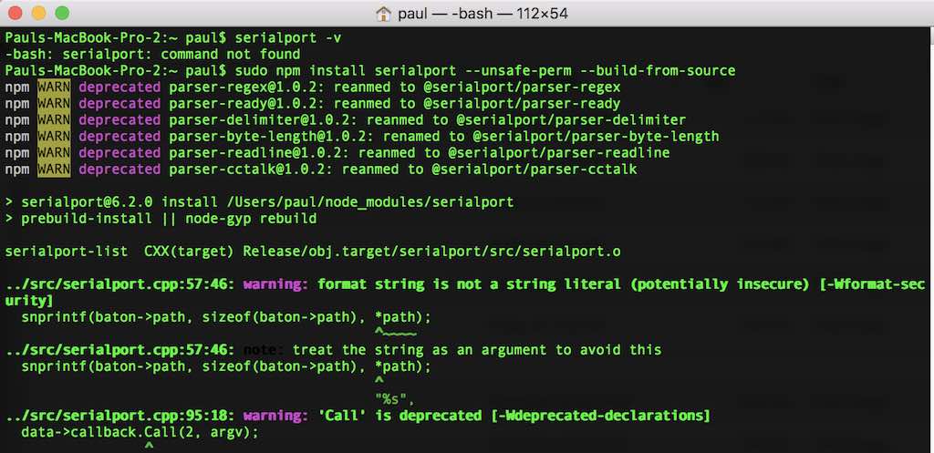
Once you have node and npm installed, verify to see if the serialport module is installed. It probably isn't, but who knows, right? Start by typing:
serialport -v
If serialport is not installed, you will get an error message that says "command not found" as shown below. To install the module, type:
sudo npm install serialport --unsafe-perm --build-from-source
:
The screen will continue rolling a bunch of messages which kind of tells you it's doing something. This is what it should look like at the end. In my case, Linux reports that Serialport 6.2.0 was installed. I type serialport-list to see if it works, and also to see if my Arduino is talking to my Mac (or Windows Laptop):
:
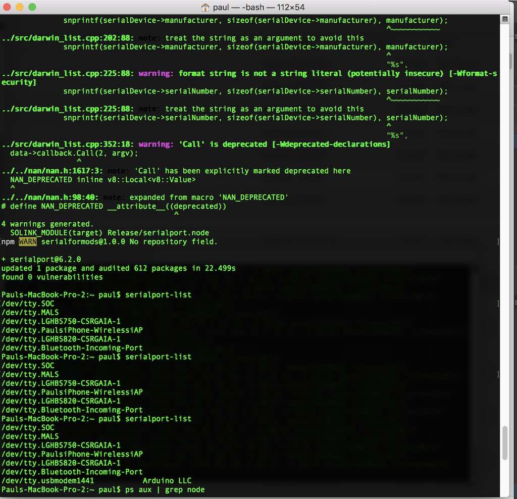
The first and second time I type the serialport-list command, I don't have the Arduino plugged in. The third time I do have it plugged in, and the list reflects this condition.
After you install serialserver, you need to identify the serial ports on your machine which you have a device connected. In my example, it is an Arduino, and it's address is /dev/tty.usbmodem1441.
The next thing you will need to do open a Terminal window and drill down to where you have your mods directory. Within your mods directory, there is a subdirectory called js. You will need to type cd js. Type ls and you will see serialserver.js listed in that directory. Once you see serialserver.js in the directory, type the following:
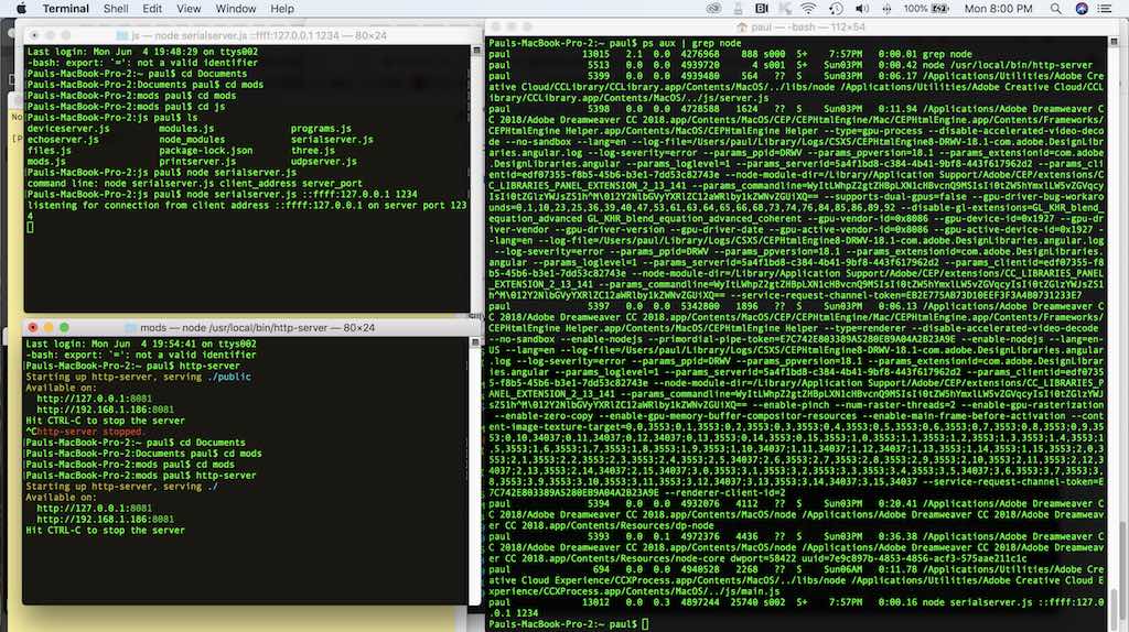
node serialserver.js ::ffff:127.0.0.1 1234
If you are successful, you will see the message "listening for connection from client address ::ffff:127.0.0.1 on server port 1234". Your dialog box should look like the top right of the following image. Just leave that Terminal window alone now. It's doing something. Next, open another totally seperate Terminal window. On the Mac, you need to right-click on the Termional icon. On Windows, you open another Powershell with administrator rights. If you follow the bottom right dialog box, I navigated into the mods directory again, and typed the following:
http-server
If everything is good, you will get a meessage about hitting CTRL-C to stop the server.
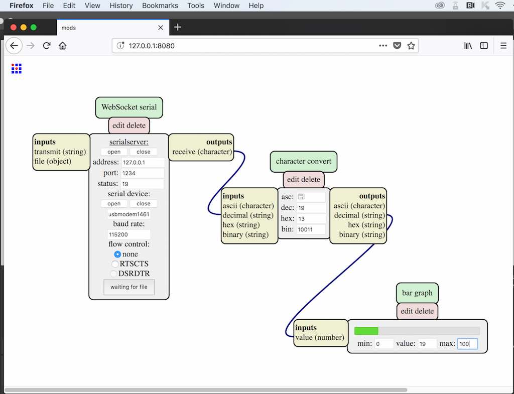
You are almost there. Next, forget about using Chrome and make sure you start Firefox. In the address, type 127.0.0.1:8080 and wait for the CBA icon. Once you get the CBA icon, you right click and proceed to install the nodes as shown in the next screenshot. They are (server) WebSocket serial, (character) convert, and (ui) bar graph.
Thank you Jake Read for your useful notes. Jake is a MIT student studying at CBA: https://gitlab.cba.mit.edu/jakeread/mkxmods/blob/master/mods/README.md
