3D Scanning and Printing
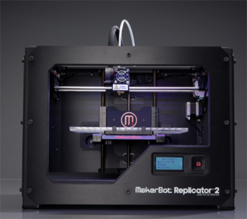
Makerbot Replicator 2
Parameters to consider when designing 3D files
A. Size of the machine:
The first thing to consider when using 3D printers is the dimension of the machine. In my case the dimensions are: 28.5x15.3x15.5. It is always good to leave a margin on the sides as it is not 100% stable.
B. The objects must be solid
An object being solid means that we have to design a closed volume. For example, we can't print a design of a surface, it needs to have a minimum volume in order to be printed. The machine needs to know what it has inside and outside the body.
C. Normals need to be oriented to the same direction
D. Object has to be no manifold:
An object can not have more than two edges in the same vertex.
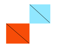
For example, if the previous picture we can see a graphic example, if we put two cubes together, that vertex will have four edges, and when the printer passes through that point to print the second cube, it will think that it has already done it and it will skip it. A solution to that problem is to give a certain width to that union.
E. Avoiding double faces.
If you start a piece from a surface, make sure you erase the surface to export the STL.
F. Printing orientation:
We have to check how is our figure going to be printed. Sometimes it will set it vertically as default and maybe is better to print it horizontally. We also have to take into account that a 3D printed object will break more easily when applying strength in the direction that it has been printed. An example of printing orientation is the following:
In order to print holes is better to do them horizontally as if you do them vertically they will have small steps and the unions won't fit as good as they should.
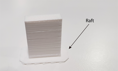
G. Support & Raft:
Sometimes we will need a support to be able to print parts of the body that are floating in the air. The general rule is that object with less than 45º will fall down when they are being printed. You can either design them by yourself or tell the
software to do it.
Raft is a base that you can put underneath the figure to un-stick it better from the machine.
H. Divide the model in pieces
Sometimes, when we have a figure that is too big or that it has different angles it is better to divide the figure in small pieces, print them separately and then stick them.
I. Filament's width:
The dept of the material that we can use depends on the nozzel. In my case is 0.4mm. My range of widths for the filament will go from 0.4 to 0.8.
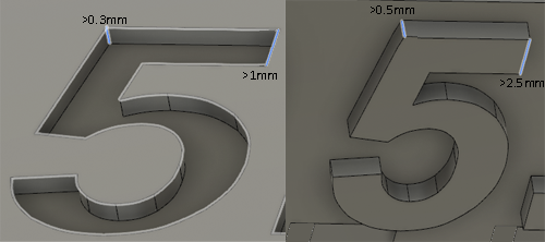
J. Walls depth:
Considering the union between two walls or the width of a wall. In the following image we can see an orientation of the widths that you need to specify in order to cut or pull properly a shape, i.e., for two walls to be separated when is specified.
K. Tolerance:
The tolerance is a parameter that you have to take into account when you are going to join pieces. Is similar to the kerf concept in the laser cutter, but in this case it depends in the characteristics of the surface.
The tolerance is an important parameter when designing the distance between two parts that are being printed together. The tolerance in the X and Y axis will be determined by the filament width and in the Z axis by the height of the layer.
Giving the pieces different tolerance levels will make two unions to be:
- - The are tight together.
- - They are tight due to the friction.
- - Movement in the union like a hinge.
L. Units:
The .stl doesn't have units. Make sure that the designs are in mm as the machines work with it. Precision of the machine in the X-Y axis is 0.01, and Z 0.0025.
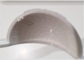
The general rule is that you can't do a floating structure but what you can do is a bridge, a structure that has support on both sides. However the width of the bridge has to be minimum in order for it not to break.
Testing the design rules
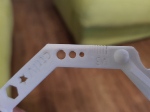
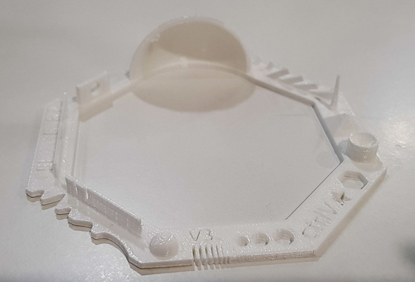
The first test I did for the 3D printer was from a design that was already done. I downloaded it from Thingiverse. You can find it in this link. I choose this template as I consider that it was very complete to check the different specifications of my 3D machine.
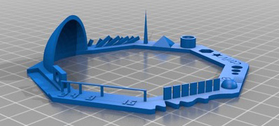
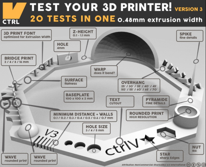
What this template tests is:
- Nut, Size M4 Nut should fit perfectly: I didn't test this one yet.
- Wave, rounded print: when you are reaching the top part, there is a bit of distance between one layer and the next one.
- Star, Sharp Edges: they are sharped.
- Name, Complex Shapes: You can distinguish perfectly the letters but they are not cutting the whole objects depth.
- Holes, Size 3, 4, 5 mm: they are about 0.15mm smaller than they should be.
- Minimal Distance: 0.1, 0.2, 0.3, 0.4, 0.5, 0.6, 0.7 mm: 0.7 and 0.6 seem to be the minimum distance that you can leave as the other ones are stick together.
- Z height: 0.1, 0.2, 0.3, 0.4, 0.5, 0.6, 0.7, 0.8, 0.9, 1.0, 1.1 mm.
- Wall Thickness: 0.1, 0.2, 0.3, 0.4, 0.5, 0.6, 0.7 mm. Same as the minimal distance, and also the walls are too thin so execpt for the two big ones the other ones tend to break.
- Bridge Print: 2, 4, 8, 16 mm: they look quite good all of them.
- Sphere, Rounded Print 4.8mm height: Looks good.
- Pyramide, 7 mm height: the top part seems to be a bit more flat than it should.
- Overhang: 25, 30, 35, 40, 45, 50, 55, 60, 65, 70°: they all look good.
- Warp, does it bend?: It doesn not bend but the top part seems to have some loose filaments
- 3D Print Font, optimized for 3D printing:
- Surface, Flatness: the shape of the numbers is not optimal. Maybe too small.
- Size, 100 x 100mm x 23.83 (10mm width): Mine has this size: 93x91x22mm.
- Hole in Wall, 4 mm diameter, check for proper print: The hole is not perfect, is is more like an elipse than a circle.
Makerbot work flow
Once you have the STL file you open the program, MakerBot, and you follow these steps.
- Click on
Prepare Add file, to open our stl file. If the file appears in black, that means that it is not done correctly.- Adjusting the shape:
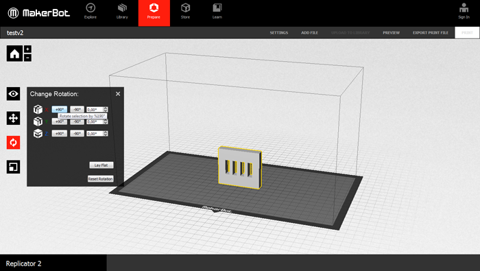
Select the shape and go toChange Position. You can change it directly by clicking the shape and dragging it or by changing the values of the X-Y-Z. Click onOn platformand onCenter.
Then you can re-scale the shape but in this case I didn't use it as I set the sizes beforehand. I used when printing the scanned object. - Go back to the View button as if you remain in the other ones you will re-scale or move your image.
- Go to settings:
You can save the file with the parameters (.thing).
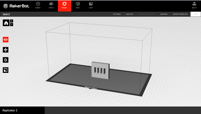
Prepare in the top menu, and then, Add File; selecting the file you desire to print.
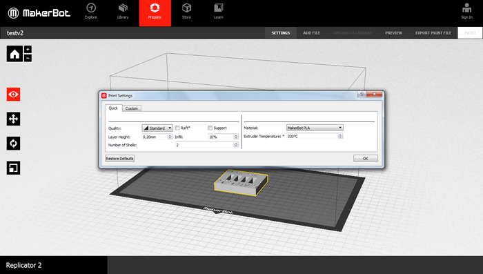
Setting the parameters
- - Before starting, click on the
Restore Defaultsas I don't know what did the previous user modified. - - Temperature: you can usually find the range of temperatures of the material in its box, 205º in my case.
- - Quality: it will change the layer height. For quick prototypes I choose 0.30 and for normal designs I will use 0.2. As I don't need for now a lot of detail and like this it will take less time.
- - Raft and Support checkbox: You can check this boxes and then check in the Preview if it has done them as you wanted or you want to do it by yourself.
- - Infill: the more filling that you put, the more time it will take. For normal tests I will use 10-15%. For machine parts 50-60%.
- - Number of shells: How many shells you want from the outside part to where the filling starts. The more that you part, the more you put the more resistant the piece will be. For big things Shells: 2. For really thin pieces sometimes is better to put more shells than increasing the percentage of Infill.
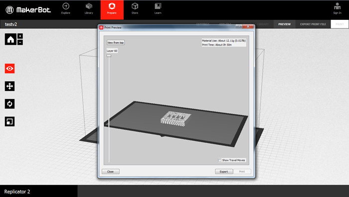
You can either send the file directly to the printer USB or you can export the file, and open it directly in the printer.
In my case I will do it in the second way. I first click on the Preview button to check how does my design look like, the time that it will take and the amount of material (in weight units). You can also see the different layers
to see if the shells are right and the Infill percentage too.
Finally, I click on the Export Print File saving the file with short names and in english alphabet. Export as X3G, SD print...
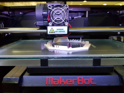
Using the MakerBot Machine
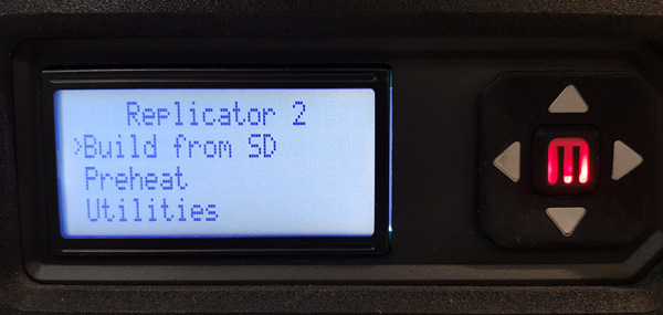
Once I had the file in the SD card I go to the machine and I follow these steps:
- - Put the filament roll in the back part of the machine and then we put the filament trough the tube coming the filament from the bottom part of the roll.
- - Turn on the machine from the back part.
- - Then, in the menu you have several options:
- - Build from SD: to select the file you want to print (first image).
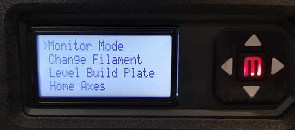
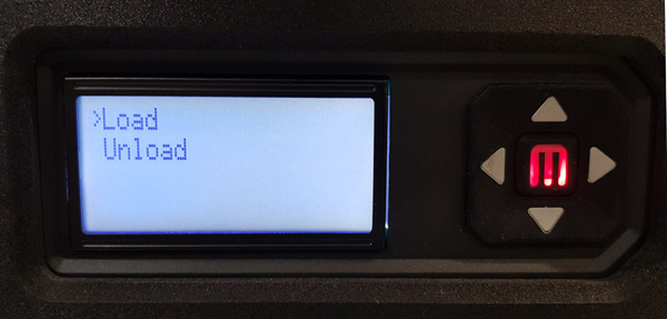
- - Utilities: there you can find the setting to
Change the Filamentwhere by clicking theMbutton you appear in theLoad/Unloadmenu (second and third image).
- - Before starting to print is a good idea to take out the base of the board to put some hair spray for the piece to fix better.
- - Once you have the filament in and board ready you choose the
Build from SDoption, you select the file you want to print and you click theMbutton.