Computer controlled cutting
Characterizing the lasercutter
For understanding the Laser Cutter machine I did the same as I did with the Vinyl Cutter. In this case, I first did a bit of research of how the laser beam worked and then what parameters does the machine need to cut or to engrave a material.
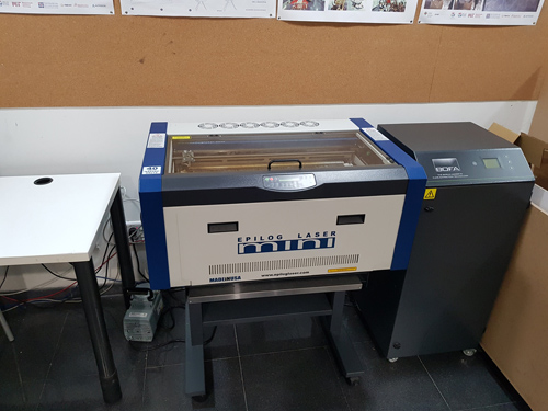
The machine that I will use for this weeks assignment is the Epilog Laser .
Apart of the speed and power, we need to consider the focal distance of the laser cutter. In my case as I used mods I used the Autofocus option the first time I send a design for a certain material.
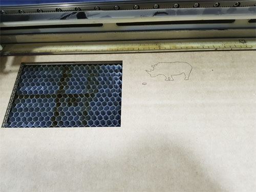
The alignment of the laser was also
a fact to consider as sometimes I was using cardboard that was already cut and I needed to specify a different x and y position than the home one.
You can modify this by changing the parameters in the mods interface or directly in the machine by selecting 'X-Y OFF->GO -> move the position to the desired one'. You can turn on the red dot to see more specify where the
laser will cut.
The material that I used was cardboard, and the parameters I needed to cut and to engrave were:
- - Speed: 20mm/s to cut and 70 mm/s to engrave.
- - Power: 45p to cut and 90p to engrave.
Calculating kerf parameter
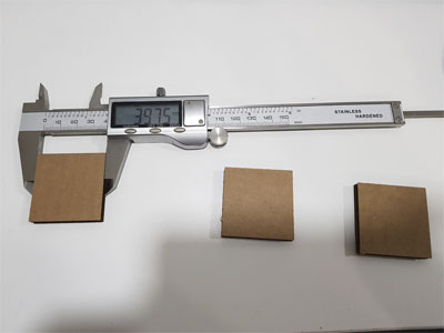
For this week's assignment I needed to create a press-fit kit and for the pieces to fit correctly I had to calculate the kerf parameter of my machine. I did a simple rectangle of 40x40mm and I sent it to the laser cutter (using mods with the .png file)
for measuring what was the real size of the rectangle once cut. The resulting width/heigh of my rectangle was 39.75 which gives me a kerf value of 0'25.
Kerf value: 0'25/2 = 0,125

Click to download .png file.
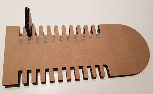
I designed a piece in Fusion 360 before having the kerf value but as I did it parametric I only had to change the values to adjust to the correct ones. I did one of the ends of the shape round and the other one square just to see how it cuts different shapes and then I did two types of cuts on the sides with different widths. For doing so, I sketched a rectangle on the surface of the board and from there I created a pattern to replicate it, giving each rectangle the corresponding width. The cardboard had 6.40 of thickness, so I started from that point and then subtracting and adding steps of 0'15.
Here you can see the resulting design that I did for this test, in the design I also have some words and shapes that I wanted to engrave but finally I just cut the shape of the piece:
Click here to download .f3d file.
Once I had the piece in Fusion I had to make this image compatible with the 'mods' interface, i.e. .png or .svg, so I projected the face in a sketch and I export it as a .dxf to be able to open it in Illustrator and export it as a .png file. Once I had my file in .png, I was able to upload it to the mods page.
Click here to download .png file.
In the same way as I did with the Vinyl Cutter, and as I just said, I used mods for the communication with the printer. One mistake that I had more than once was not to check the size of the .png file when I uploaded the image ending up
with tiny pieces.
Once I had cut the piece I tried what was the optimal width of the sockets and I decided to use 5.80 mm as I wanted the pieces to be tight.