Electronics design
Measuring the board
I used two devices to measure my board components. One was the Multimeter and other one was the Oscilloscope.
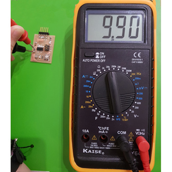
1. I first used the Kaise MY64 multimeter:
Measuring the resistance value: in order to check if they were working properly I used the 20K option to measure the 10k resistance and then the 2K to measure the led resistances of 470 and 330 ohms. You just need to move the wheel when the multimeter is switched off to the option you want and then place the plugs on both sides of the resistances.
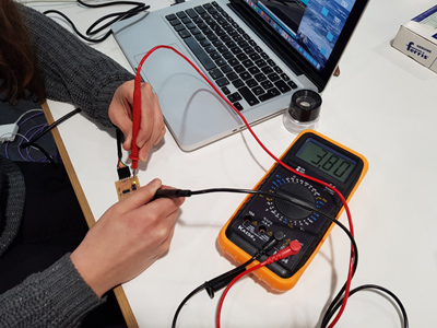
Measuring the voltage: I used the continuous current option to measure the voltage value between components. I measured from side to side of the LED using the 2V option.I also measured from side to side of the resistance observing, as is expected, a loss of voltage. I also checked that from the VCC to GND I had 5V.
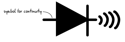
Checking the continuity:
Is important to check the continuity of a circuit, not only to check that the components are really connected between them but also to check that we don't have a short-circuit. The way of doing this is by selecting the continuity symbol on the multimeter and placing the plugs over a trace or component connected to GND and other to VCC.
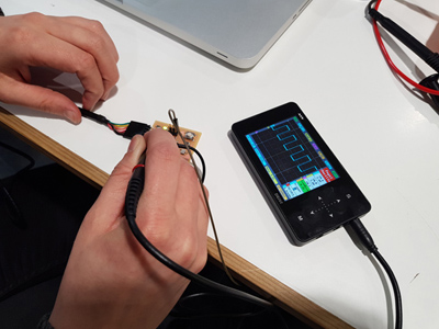
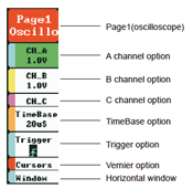
2. Then I used the Saint Smart Osilloscope DSO NoteII.
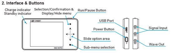
For using this oscilloscope we need to connect the probe to both ground and the part we aim to measure.
>When I used the Oscilloscope I had compiled one of the example programs in arduino, the Blink one, to see how the signal in the oscillatory was changing. You can see in the square signal of the screen when the light was turning on and off.