Input devices
Measure the analog levels and digital signals in an input device.
For this week's assignment we had to measure the analog levels and digital signals in an input device. We started by measuring some circuits with the Saint Smart Osilloscope DSO NoteII.
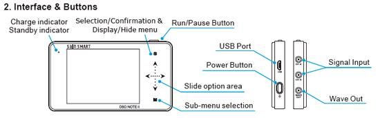
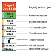
For using this oscilloscope we need to connect the probe to both ground and the part we aim to measure. Then we go to the menu and we enable the channels that we are going to read. In this case we were only measuring with the Channel A. you can also modify the voltage that will be represented, the timebase and how the signal will be displayed, if we are going to start reading when a trigger that we have set up occurs or if it is reading in an automatic way. In this assignment we read the signals from different circuits:
1. A circuit, connected to Arduino for the power supply, with a LDR.
2. Voltage variance when the we change the power of the potentiometer:
3. Moving the accelerometer to see changes of voltage in the Y axis:
Using Saleae to measure input signals
We also used Saleae logic analyzer to measure and visualize the signals in our electrical circuits. We used the board of Week 07 running first a program that will light up the LED with different delay times.
#include <SoftwareSerial.h>

SoftwareSerial mySerial(0, 1); // RX, TX

const int id = '1';
const int ids = 1;
const int ledPin = PA3; //PA7
int ledState;


void setup() {
pinMode(ledPin, OUTPUT);
mySerial.begin(9600);
}

void loop() {
  if (mySerial.available()>0){
    ledState = mySerial.read();
    if (ledState == id){
      digitalWrite(ledPin,HIGH);
      delay(500);
      digitalWrite(ledPin,LOW);
      delay(500);
      digitalWrite(ledPin,HIGH);
      delay(500);
      digitalWrite(ledPin,LOW);
      delay(500);
      mySerial.println(ids);
  }
  else{
      digitalWrite(ledPin,HIGH);
      delay(500);
      digitalWrite(ledPin,LOW);
  }

  }
  delay(10);

}
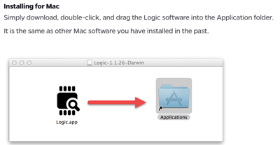
Downloading the required software:
We downloaded the software from the webpage.
Connecting the wires to the board
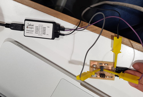
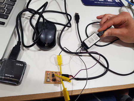
To measure analyze our signals we need to plug the pins of the Salea analyzer to the pins that we are working with. In this case the two connected to the LED and to ground.
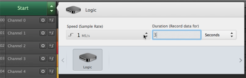
Working with logic.app
In this case we just need to know to what channels we have pluged our pins, conect it to the usb port and stablish how many seconds do we want to record on the start button.
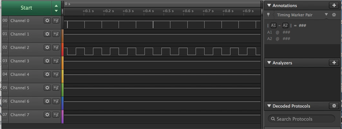
Here we can see how the voltage is changing when the LEDs being on and off. In this case one was connected to channel 0 and the other one to channel 2.
Analysing serial signals
We also analyze the signals when using the serial port. For doing so we uploaded Neil's hello.ftdi code. Then we changed the connectors to the pins that we had defined as RX and TX.
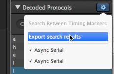
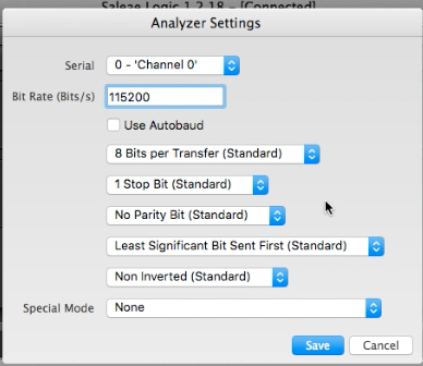
This time we had to create the signal Analyzers for both RX and TX channels. The way of doing this is by clicking on the + symbol on the right of Analyzers->Async serial.
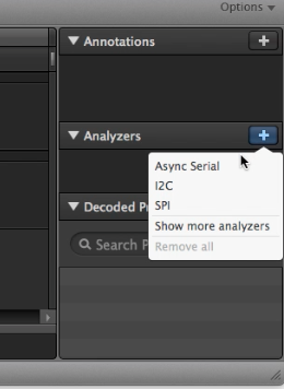 And then choosing the channels that we are using and modyfying the baud speed according to the one we have in our board.
 When this is ready we can open a serial monitor to send the letters to the microcontroller and like that we can see how the communication is done with the analyzer. You can also modify the way the information is being displayed (binary, dec, ASCII...) This is shown in the next video:
Data can be saved in the computer.