Week 4
Computer-Controlled Cutting
1. Vinyl Cutting
- Stickers.
- Flexible circuit boards.
- A textured surface/relief pattern.
- Screenprint resists/stencils.
Learning outcomes:
- Identify and explain processes involved in using this machine.
- Design and create the final object.
Have you:
- Explained how you drew your files.
- Shown how you made your vinyl project.
- Included your design files and photos of your finished project.
Individual assignment:
Vinyl Cutting
1. Processes involved in using vinyl machine:
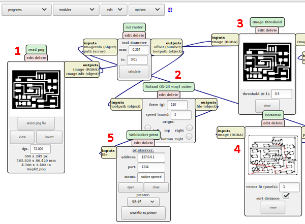
For this week's vinyl assignment I have used Roland's CAMM-1 GS-24 Vinyl Cutter and the 'mods' interface to upload my files and change the parameters in order to cut properly the material that I was going to use.
The first thing I had to do was to understand the parameters that this machine uses and how to choose the right ones. These parameters vary not only depending on the material that you are using but also with conditions like humidity.
- Pen force: the pen force you apply the deeper the cut will be (gf).
- Speed: is important not to choose a very high-speed, specially when cutting round edges, as the vinyl could break (cm/s).
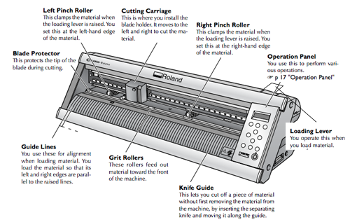
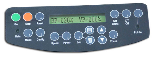
Once you have chosen the parameters you have to prepare the machine (the buttons that I refer to are shown in the next picture):
- Introduce the material in the machine.
- Make sure it's aligned properly so it doesn't twist when cutting.
- Set the pinch rollers in the correct positions (in the different white marks depending on the material size.
- Once you have done this, you pull down the loading lever.
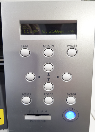
- Press the ON button and select the type of material you are using (roll, piece or border). The machine will display the width of material you have available if you select the roll option and both the length and width when using a piece. You must consider these dimensions in order to cut your design.
- Press the setup button to know what power and speed you are using (110gf, 2cm/s). If you want to change these parameters you have to go to Menu -> Condition -> And you change the power or speed.
 Once I had the machine set, I went to the computer: Open terminal:
 cd mods -> http-server and another one sh start.
Then, go to the 'mods' site. In my case I worked with the open server program, where I selected vinyl cutter -> GX-24 -> cut.png / cut.svg.
- Upload your image, in this example .png. Check that the size of your file is correct.
- Enter the speed and force parameters that were written in the machine.
- Click on the calculate button.
- Check in the vectorized image that your design is correct.
- Send it to the printer.
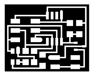
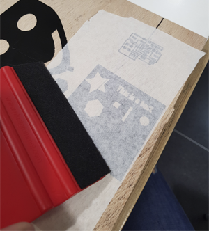
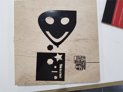
Following these steps I did three tests before printing my week assignment in order to practice not only with the cutting but also with transferring the vinyl to the paper that enables you to stick it where you want. The first picture shows the circuit template I cut to practice the unsticking of small pieces. The second one shows how I was taking out the bubbles of my transfer paper and then, the last one is the final result of my three tests. I tried both, peeling off all the pieces of the design that I was not using before and after sticking the transfer paper, and I found easier to peel them beforehand.
2. Designing and creating the final object:
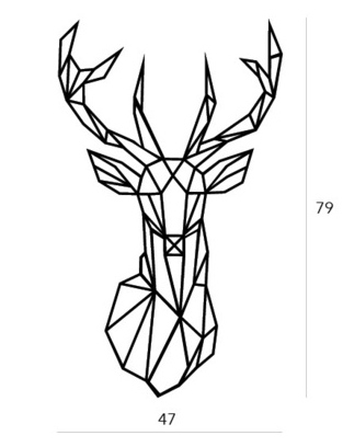
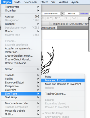
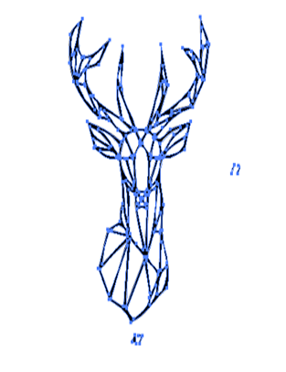
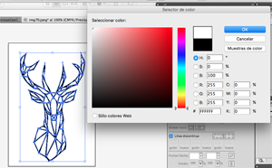
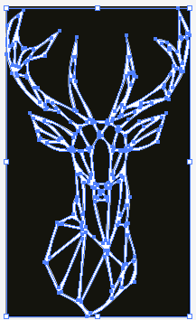
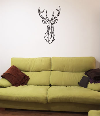
I wanted to print a wall decoration for my living room and I liked this one with the shape of a reindeer. I downloaded an image that was available on the internet and I used Illustrator to expand the lines and create the traces. I set the lines to white and the background to black and then I exported the image with .svg format in this case, as the image was to big to export as a .png.

3. Cutting the reindeer vinyl:
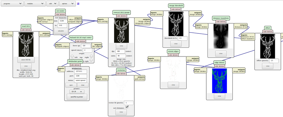
I scaled the image in relation to the width of the vinyl paper, and following the steps that I mentioned before for using mods with the vinyl machine I printed it. In this case using the .svg option.
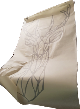
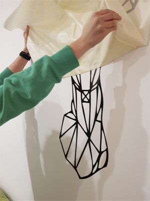
I decided to take out the extra parts before putting the transfer paper as I found it easier when doing the tests. I had some issues with the transfer paper. First because I got some bubbles when sticking this transfer paper to the design and second when removing it to stick it to the wall, as the design is big, I needed some help. Anyway, the final result was (nearly) perfect!
Laser Cutting
Group assignment
Individual assignment
Learning outcomes:
- Demonstrate and describe parametric 2D modelling processes.
- Identify and explain processes involved in using the laser cutter.
- Develop, evaluate and construct the final prototype.
Have you:
- Explained how you parametrically designed your files.
- Shown how you made your press-fit kit.
- Included your design files and photos of your finished project.
Group assignment:
Group assignment pageLaser Cutting
1. Characterizing the lasercutter:
For understanding the Laser Cutter machine I did the same as I did with the Vinyl Cutter. In this case, I first did a bit of research of how the laser beam worked and then what parameters does the machine need to cut or to engrave a material.
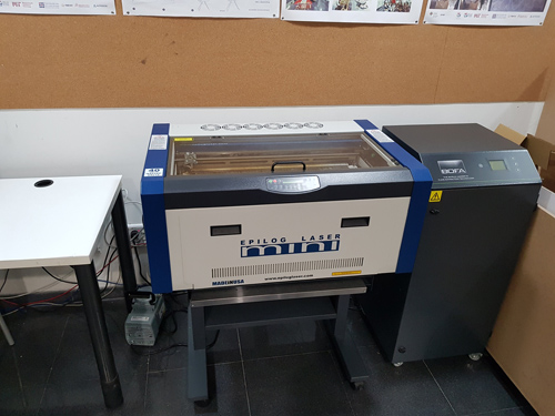
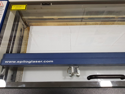
The machine that I will use for this weeks assignment is the Epilog Laser .
Apart of the speed and power, we need to consider the focal distance of the laser cutter. In my case as I used mods I used the Autofocus option the first time I send a design for a certain material.
The alignment of the laser was also a fact to consider as sometimes I was using cardboard that was already cut and I needed to specify a different x and y position than the home one.
You can modify this by changing the parameters in the mods interface or directly in the machine by selecting 'X-Y OFF->GO -> move the position to the desired one'. You can turn on the red dot to see more specify where the laser will cut.
The material that I used was cardboard, and the parameters I needed to cut and to engrave were:
- Speed: 20mm/s to cut and 70 mm/s to engrave.
- Power: 45p to cut and 90p to engrave.
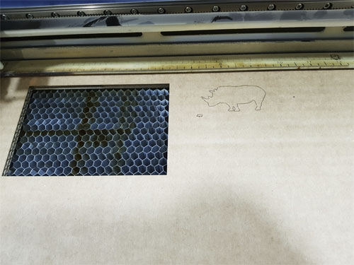
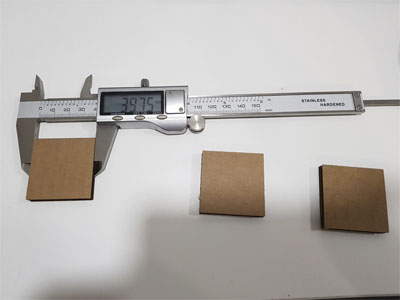
2. Calculating kerf parameter:
For this week's assignment I needed to create a press-fit kit and for the pieces to fit correctly I had to calculate the kerf parameter of my machine. I did a simple rectangle of 40x40mm and I sent it to the laser cutter (using mods with the .png file) for measuring what was the real size of the rectangle once cut. The resulting width/heigh of my rectangle was 39.75 which gives me a kerf value of 0'25.
Kerf value: 0'25/2 = 0,125

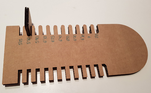
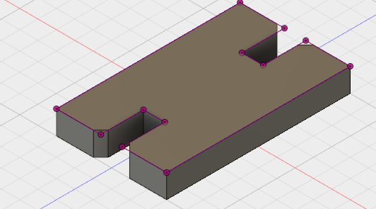
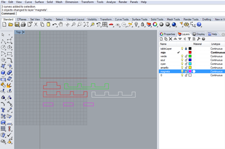
I designed a piece in Fusion 360 before having the kerf value but as I did it parametric I only had to change the values to adjust to the correct ones. I did one of the ends of the shape round and the other one square just to see how it cuts different shapes and then I did two types of cuts on the sides with different widths. For doing so, I sketched a rectangle on the surface of the board and from there I created a pattern to replicate it, giving each rectangle the corresponding width. The cardboard had 6.40 of thickness, so I started from that point and then subtracting and adding steps of 0'15.
Here you can see the resulting design that I did for this test, in the design I also have some words and shapes that I wanted to engrave but finally I just cut the shape of the piece:
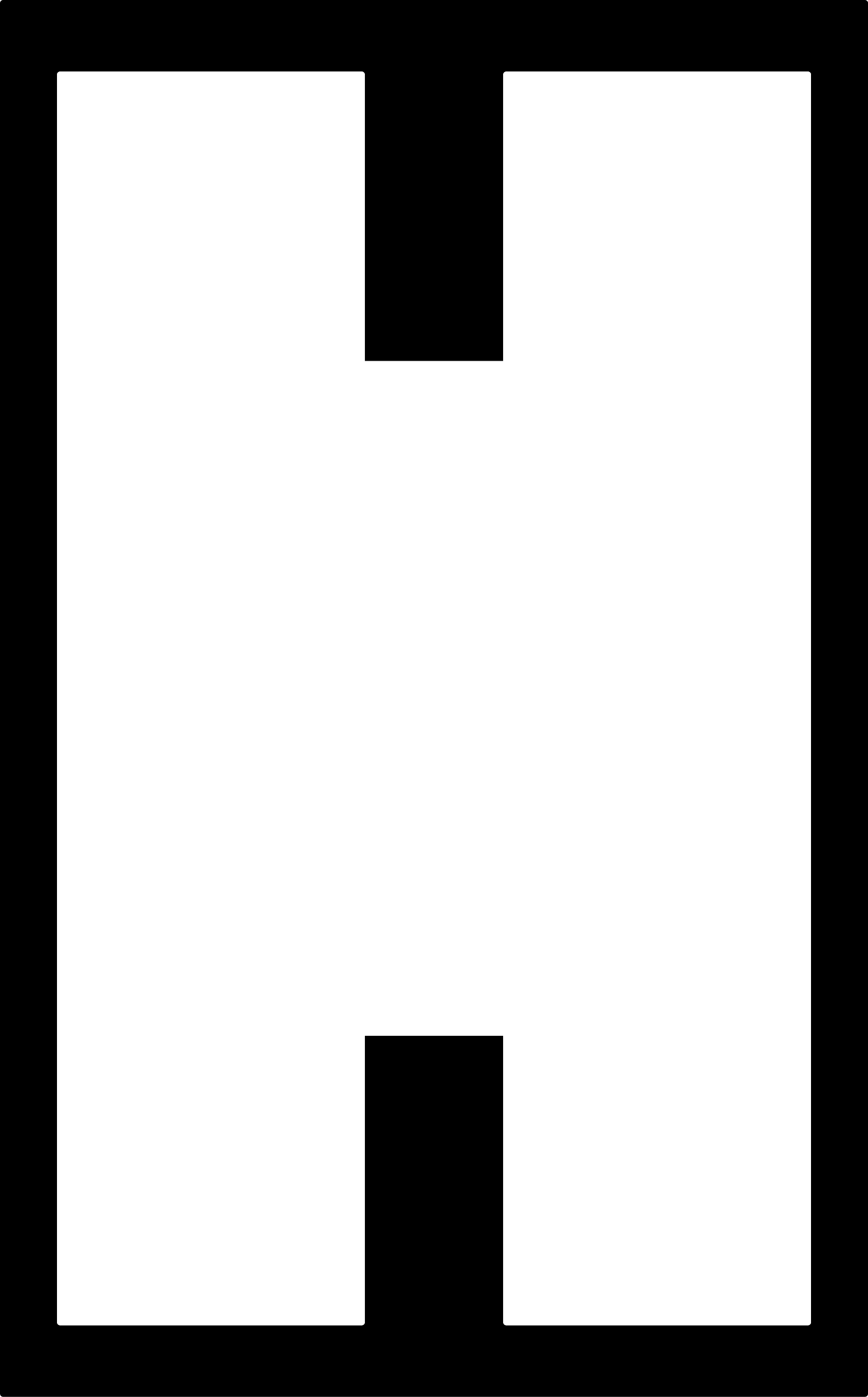
Once I had the piece in Fusion I had to make this image compatible with the 'mods' interface, i.e. .png or .svg, so I projected the face in a sketch and I export it as a .dxf to be able to open it in Illustrator and export it as a .png file. Once I had my file in .png, I was able to upload it to the mods page.
In the same way as I did with the Vinyl Cutter, and as I just said, I used mods for the communication with the printer. One mistake that I had more than once was not to check the size of the .png file when I uploaded the image ending up with tiny pieces.
Once I had cut the piece I tried what was the optimal width of the sockets and I decided to use 5.80 mm as I wanted the pieces to be tight.
Individual assignment:
3. Constructing a parametric press-fit construction kit:
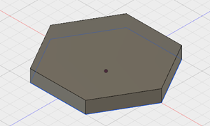
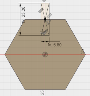
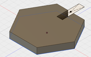
Knowing the optimal width I created three parametric designs that will compound my press-fit kit. I did a hexagon, a square and a shape that is useful as a union between the pieces. The process that I followed to create the hexagon was the following:
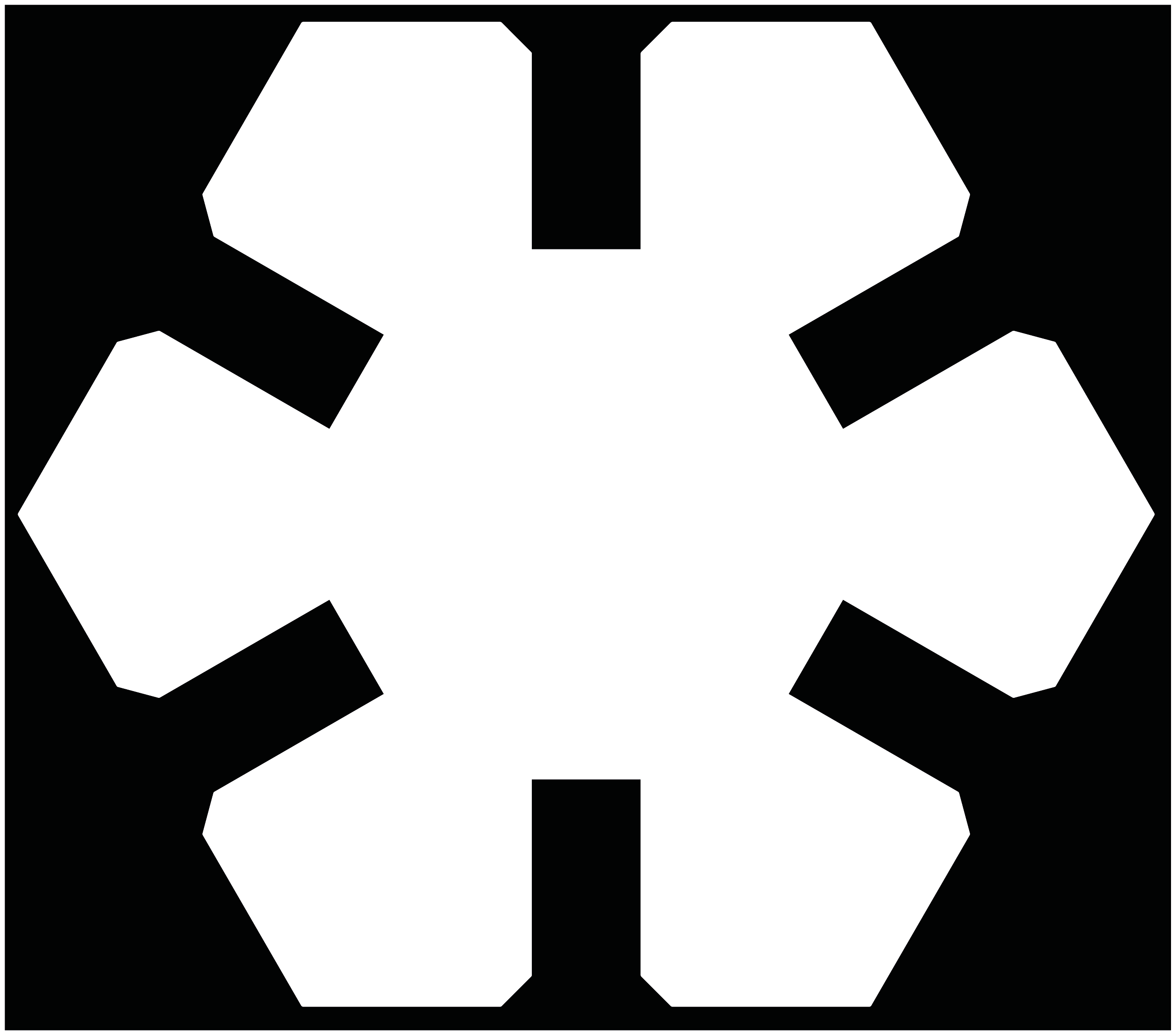
I exported this sketch as a .dxf and I opened it on Illustrator in order to change the format to .png. These two images are the .png that I sent to the printer. First I sent two pieces in order to check if they were the right size and if they fit properly and then I cut fifteen of them.
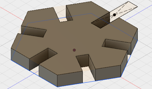
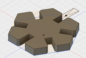
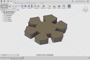
The second piece I did was a square, as I though that this shape will allow me to fo the structure of the constructions. I followed a similar process to the hexagon. I created a centered square and I sketched a parametric rectangle on the surface in order to cut the body. Once I had the first cut I did another circular pattern, with 4 repetitions, to cut the center of all the faces and then I chamfer the corners. Here you can see the final result:
Once I had the sketch I converted it to .dxf. This time I had a problem, when I imported the .dxf to Illustrator, as the units were set to 'points' when I imported my file, the dimensions of my square were wrong. I didn't realize these dimensions were wrong because I didn't check in the mods interface so I cut a tiny square. So I changed this software parameters and then I imported the file again. My file was ready to be exported as a .png.
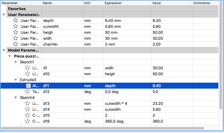
The last shape I created was this one that it is useful as a union between the other pieces. In this case the circular pattern had only 2 repetitions as I didn't want to cut all the faces. In the next table you can see the parameters that I gave to this shape. I continued using 5.80mm for the width of the cuts for the pieces to be tight; 6.40 is the depth of the cardboard and the dimensions of the piece are 50x30mm.
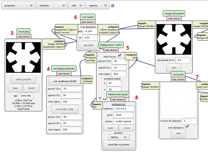
4. Using mods with the laser cutter:
Once you know how to use mods with other machines it becomes easier to learn with a new one.
- In my case: Open two terminals, one for the servers
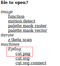
cd mods -> http-serverand the other one with the file that has the starting process for the serverssh start.Go to the mods site and open a server program. - Select the Epilog .png in my case.
- Upload the .png file and check that the sizes.
- Select the material that you are using, cardboard in my case.
- Select the position where you want to start cutting.
- Calculate the trajectories.
- Check that is cutting as its desired.
- Send it to the printer.
Changing the position of the laser:
Sometimes when we want to cut a board we want to start in another point that is not the (0,0) one. We can do that by pressing in the Laser machine: X-Y and the GO; we can set to see the laser dot, and then we move manually the head of the laser to the desired position. Then we press Set Home and once this is done we click on Reset.
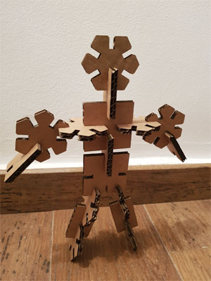
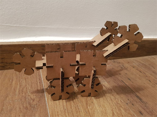
5. Final result of the press-fit kit:
This kit can be used to create different shapes as you can see in this two pictures. I create two shapes that are suppose to be a human and a wheelbarrow but this depends on the imagination of the kid that plays with it, as that is it's purpose!
6. Cutting and engraving methacrylate:
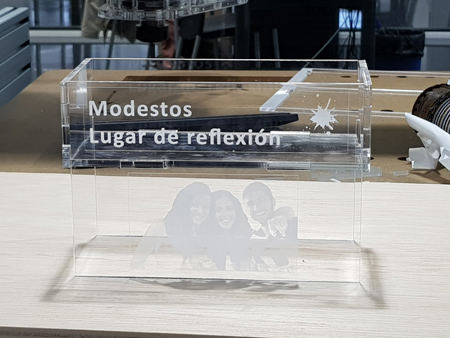
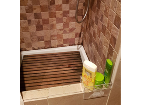
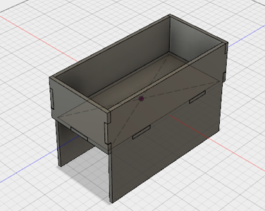
Appart from working with cardboard I wanted to do a structure that I will use as a storage for my bathroom with methacrylate. Learning from this the parameters needed for working with this other material and also learning how to engrave a material by placing a picture and some letters on one side of my structure.
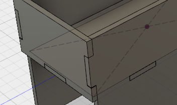
I first measured the size of the storage structure that I needed for my shower, and then I did the design in Fusion 360. Doing a parametric design as I designed before measuring what dimensions I had to give to the tabs in order to the pieces to fit strongly with each other leading in a stable structure.
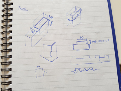
Measurements that I had to check before cutting the final piece:
- Height and width of the tabs that will be joining the pieces.
- Holes where the tabs will be inserted.
- Engraving parameters.
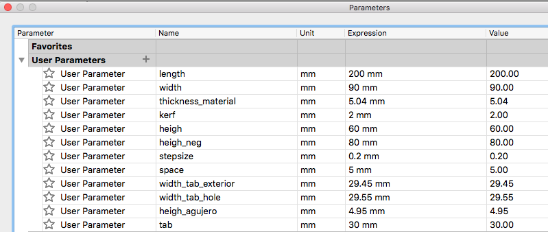
For doing so I created a sketch with the different widths that I had to give to the unions for them to fit properly. Instead of using 30mm I used 15mm width for reducing the material waste.
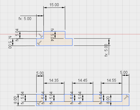
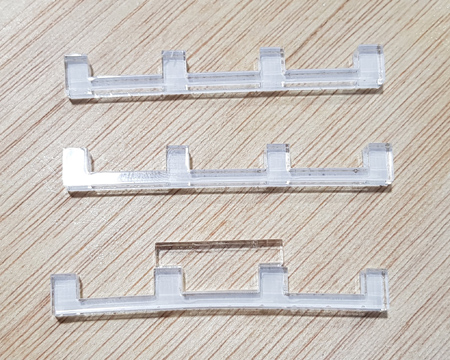
The best fit was 14.45 (for 15mm tab), so the width that I gave to the final unions was 29.45, being the tab 30. I also tested what width and height the holes (that make the union between the base and the front and back part) needed. In this case the result was: 29.55 x 4.95 mm , being the tab size 30 x 5.04 mm .
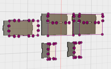
Once I had the measurements I added / changed them in my parametric design. I did a copy of the components, making them flat, and then I projected them into a new sketch. Once I had done this I was able to export the pieces as a .dxf to cut them.
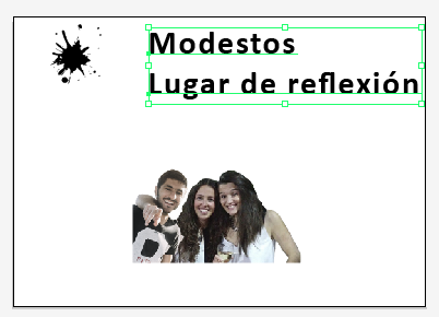
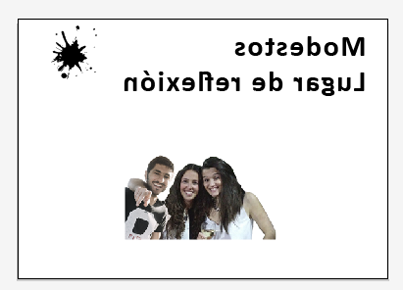
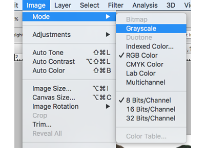
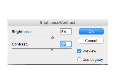
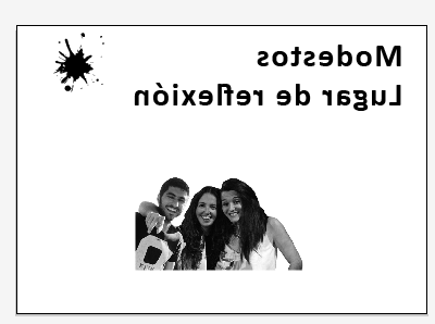
 When I had the structure of the storage structure I designed what I wanted to engrave in my piece. I first added a text, that I had to mirror, as I was going to engrave the interior of the front part of my structure. And then I had to modify the image as I wanted it to be in grayscale and give it a bit more brightness and contrast.
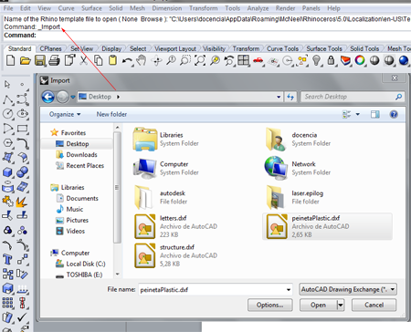
Software: using the Laser cutter with Rhino:
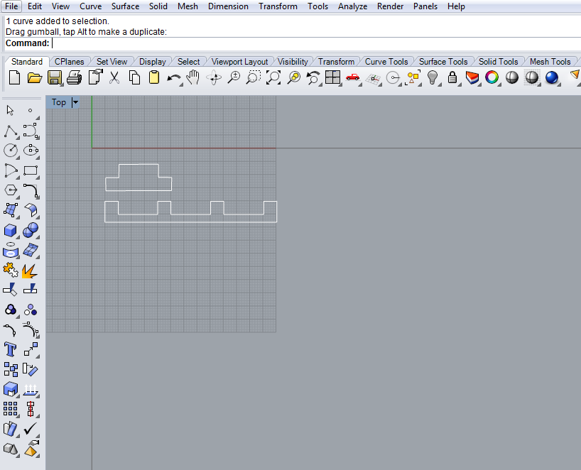
This time, instead of using mods for cutting, I used Rhino in order to cut and engrave my material. I first cut the tabs that I was going to test, so as they were saved in a .dxf I imported them and I placed them.
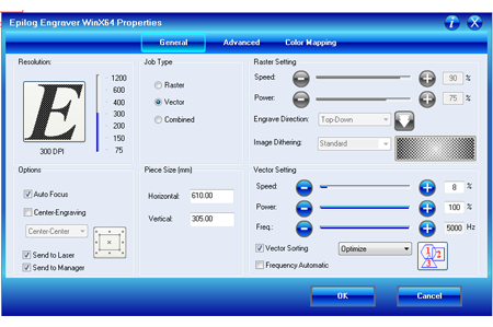
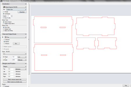
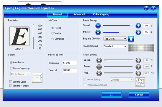
When I had the pieces displayed in the correct position I went to the print options and is there where you have to insert the parameters. I looked in the pdf where I have the different materials that can be used and which parameters to use with them and I looked for acrylic:
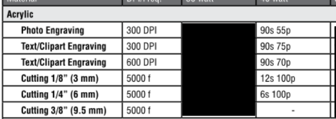 So I went to the printer properties and I inserted those parameters: speed: 8s and power = 100p, I didn't set the speed as 12s or 6s because my material has a thickness in between those two (5.04).
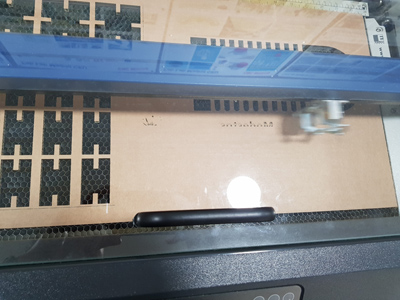
Engraving with Rhino:
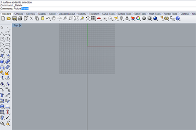
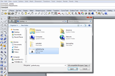
For inserting an image we don't follow the same process as before, instead of importing the file we have to open the 'PictureFrame' utility, we can just write it in the command line, and choose the image we want to engrave.
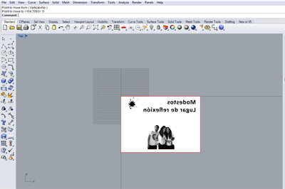
When the image is placed and with the correct size we open the Print window and we set the parameters to engrave the material, choosing the Raster menu in this case.
I did some test to see if the image will be engraved properly or no. We did as part of a group assignment two tests with different intensities of engraving. The links to the tests files are the following:
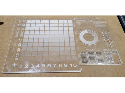
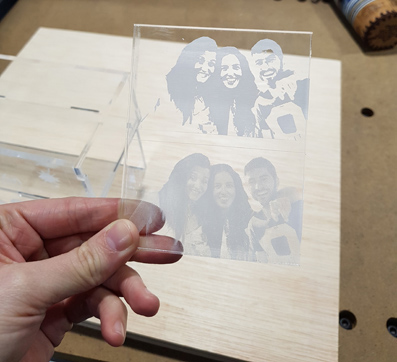
I did two more test engraving the methacrylate because my picture didn't have enough quality and it was not that easy to have a good result when engraving it.
So, after all this process I now have my storage structure for the shower! My flatmates really appreciate it!