Week 5
Electronics Production
Group assignment
Individual assignment
Learning outcomes:
- Describe the process of milling, stuffing, de-bugging and programming.
- Demonstrate correct workflows and identify areas for improvement if required.
Have you:
- Shown how you made and programmed the board.
- Explained any problems and how you fixed them.
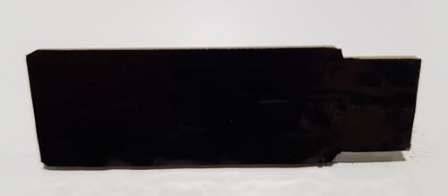
- Included a ‘hero shot’ of your board.
Group assignment: Group assignment page
1. Characterization of the PCB production process:
Whenever we have a board we need a programmer to work with it. Some of the big boards include this programmer, others include a Bootloader (still needing a programmer the first time), but in general you usally need a programmer in order to communicate the board with the computer.
In this weeks assignment I have learned how to milled a board, solder the components and program it to be able to communicate the computer with the board.
One fact to take into account when producing a board is the lifetime of the milling machine tools: they will be useful for a short time and then they will start to create rough edges.
Another one is the zeroing: lowering the machine to the surface and position the tool to the correct height.
Materials:
- FR4: epoxy glass. Generally, is the most used material but we won't use it as is dangerous for health and also because the tool will wear out fast.
- FR1: not as good at high temperatures but it machines beautifully.
Sacrifice layer of the machine: what you put on top of the machine in order not to break the tool. It is located on top of the work plate to protect the tool.
- You smoothly put a bit of the solder
- You wait to the right temperature (10s aprox)
- The solder will flow up and down
- You take out the solder
2. Trying different tools:
For this week's group assignment we tried milling PCBs with two different tools: the 1/64 endmill and the 20º 0.1 mm V-shaped Engraving Bit.
A. 1/64 endmill:
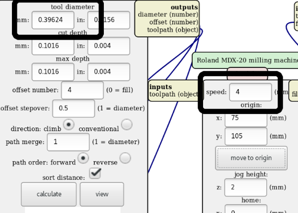
We downloaded the line test image to test the different widths that can be given to the traces using mods to mill with the Modella MDX 20. The process of using mods for PCB production is explained later on. For this tool the parameters are already by default in moods when selecting 1/64. The tool diameter is 0.39624 and the speed 4 mm/s.
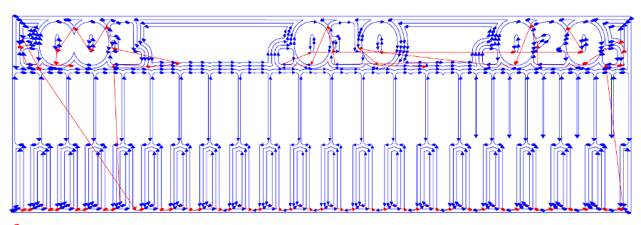
It can be observed on the 2D raster that after .015 the division between the traces disappears. What we want to see also is if the thinner traces remain when being milled.
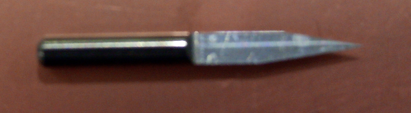
B. 20º 0.1 mm V-shaped Engraving Bit
The second tool that we tried was the V-shaped engraving bit.
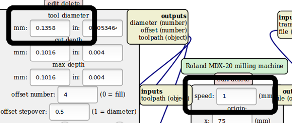
In this case the tool diameter and the speed are not giving by default. They need to be calculated. For doing so we drew the shape of the tool giving it the 20º angle that it has. What we need to consider is the max depth that we need to reach to mill the copper which is 0.1016 mm. Giving that measurement we look in the drawing to what diameter corresponds that depth: 0.1358. That is the tool diameter that we are looking for.
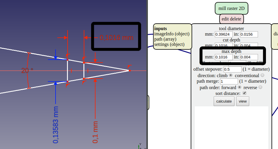
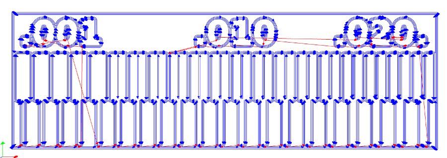
So we set those parameters in mods and we calculate the 2D raster. In this case it can be observed that the separation between traces will be milled properlly until 0.005 approximately as this tool has a thiner dimater.
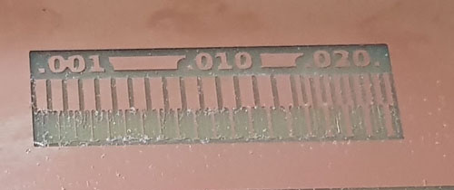
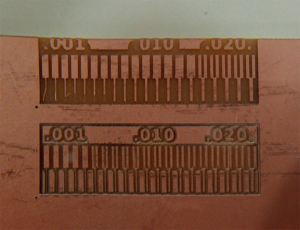
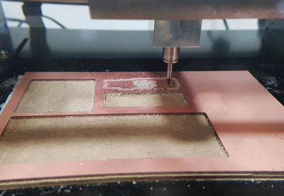
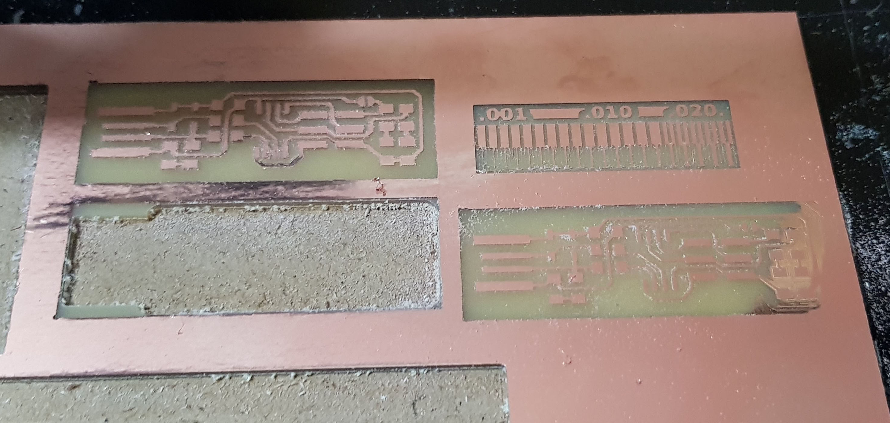
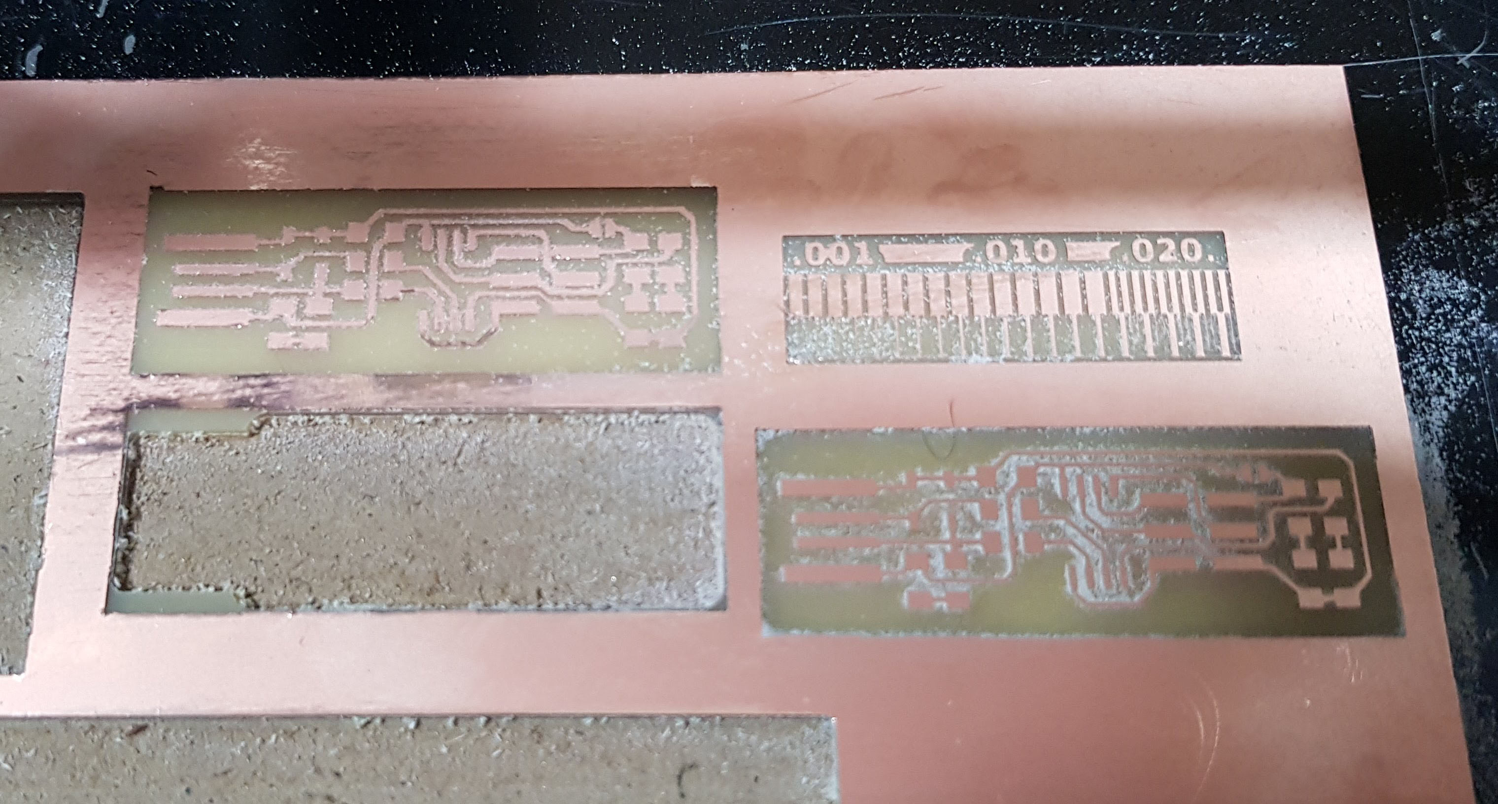
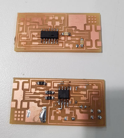
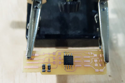
Result of the milling PCB tests
The next pictures show the results of the different tests. The two top pictures have been milled with the 1/64 tool whereas the bottom one was milled with the v-shapped tool. The differences between these two is that with the 1/64 as it has a bigger radius you can't create small separated traces whereas with the v-tool you do. But on the other hand the traces that have been milled with the second one are not fixed as they should.
Individual assignment:
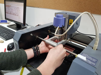
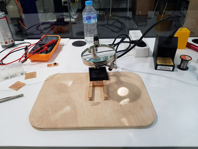
Previous steps with the machine:
First thing I had to do was to press the ON button to turn on the machine. Once you have done that the machine will move to the right side and the table will come to the front. Then, in order to be able to change the location parameters in the computer we press the button VIEW.
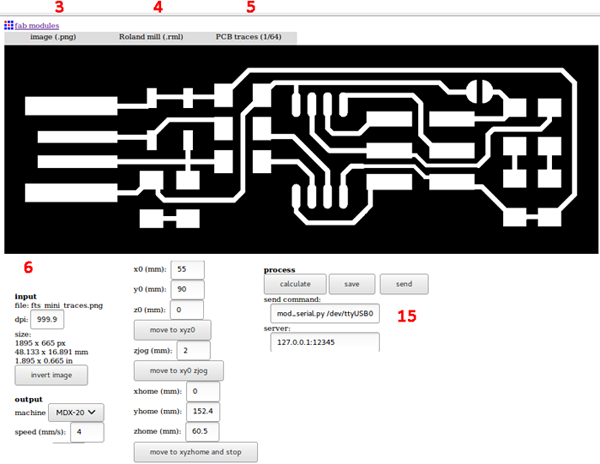
Using Fabmodules:
I will use FABMODULES to send the file to the Modela MDX20 machine, as MODS was not working properly. In the opposite way as last week, I will work with the online server.
- Open a terminal and I write
sh fab_modules, that will open the fabmodules file and will turn allow the comunication between the computer and the machine withnode.js. - Go HOLA!! to the FabModules website.
- Input: Image .png
- Output: Roland-mill(.rml).
- Process: PCB traces / outline, depending on what you want to do. In my case I started with the traces.
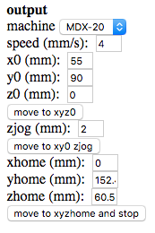
- Output parameter section: Machine: MDX-20, and we leave the default speed (4mm/s).
- Making the change of tool accesible: set x0 = middle (80). I had turned on my machine previously and clicked on the
VIEWbutton, so my machine was on the left corner. To make the insertion of the tool easier:
I changed the x0 parameter, in the output section, to the half (80mm) so I can access better when inserting the tool. You have to be careful when introducing it, to not to touch its tip, as you could break it, especially the 1/64 for. - Move the head of the machine to a centered position of the board, x0 = 120 and y0 = 60 to set the z distance.
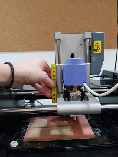
- You now press the
DOWNbutton in the machine until you have 0.5 cm distance in the speeder unit (see picture) - I released the screw, holding the tool, and I left it touching the board. Then I screw it again.
- Decide in what x-y position I wanted to start and I introduced that value in x0 and y0 (55,90).
- Pressing
move to xy0 zjog, notmove to xyz0as for going to that position you need to lift up a bit the tool for not scratching the board. - And once I have the pointer in the desired x-y position I pressed
move to xyz0, so the pointer moved down to z = 0. - As now I am in the case of milling the traces, I will change the number of offsets to -1 to remove all the unnecessary parts.
- CALCULATE, waiting until it finishes.
- SEND
Milling the outside part:
Once it finishes, the head of the machine will move to its origin. You can then take out the tool and exchange it to the one for the outline (1/32).
I changed the type of process to PCB outline, in the fabmodules interface, and as I was working with the same window my machine was already selected.
I set x0 and y0 more or less to the center of the board, as done previously, and I clicked on the move to xyz0 as the x0 and y0 parameters are not changing, and then I un-screwed the tool until it touches the board, as I did before, and I tight it again.
Finally I introduced the values of the position I set before as the origin (step 10, x=55, y=90), I clicked on move to xy0 zjog for the pointer to move without scratching and then you press move to xyz0 to set the z = 0.
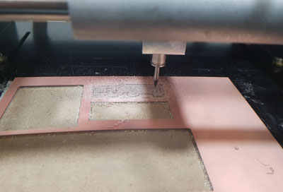
Issue 1: The resulting traces of the board had rough edges which indicates that the tool that was been used was old (lifetime concept), so I decided to change it to a new one and repeat the milling of the traces in another position (106,68).
Issue 2: When doing this second attempt, I realized that the right part of the design was not been milled properly, that was due to the difference of thickness of the material . What was causing this was that it was not stuck evenly to the sacrifice layer. To solve that problem I first tried by changing the milling depth to 0.12 instead of 0.10 but the problem was still there, so the solution was to recalculate the z0 right side of the board.
Final result :
Before having the problem with the server I learned how use mods to send the file to the Modela MDX20 machine.
- Upload file, check dimensions
- You choose the tool you will use (1/64" or 1/32")
1- We choose the 1/64" to mill the traces.
2- Change to the 1/32" one in order to do the outside.
Parameters: dm, depth = we don't usually have to change them.
Offset = number of iterations that you will do engrave your shape: minimum 4 to have a proper separation between traces. - Change the x and y position to the center of the board for calculating afterwards the z position. We leave the speed as the default.
- Mill raster parameters: sometimes we will need to change the depth, as I did when the board was not being cut properly. We can set the offset = 0 to remove all the unnecessary parts, it will only leave the traces. In my case I will set it to 0, but in bigger boards this process will be very slow.
Stepover = how much it overlaps from one iteration to the other. We will leave the 0.5 default. - Send file.
IMPORTANT: Check with the original file how it is going to mill, to see if it's milling all your shapes.
2. Making an in-circuit programmer:
Once I had milled the board and I had washed it, I started the soldering process.
Before starting I needed to know which pieces to put, which ones had an orientation and where I had to put them.
- ATtiny45small: Directional, it has a circle in the bottom left corner
- Two 1kΩ resistors
- Two 499Ω resistors
- Two 3.3v zener diodes, marked with a line on the cathode side.
- One red and one green LED: they have a green line to know the direction.
- One 100nF capacitor
- One 2x3 pin header
How to solder the components:
I took some 'rectangular' tweezers as I found them more manageable to move the components to one side to the other. I did some tests before starting with the final board.
Tips:
- Wet the sponge for cleaning the tip of the heater.
- Cut the a piece of solder from the roll to work better with it.
- Put some flux on the board for transmitting better the heat and a better fixing.
- Start from the bottom to the top and inside out.
- Checking that there is continunity between the components.
Desoldering: I learn three techniques that I could use to desolder components or to remove extra soldering bits:
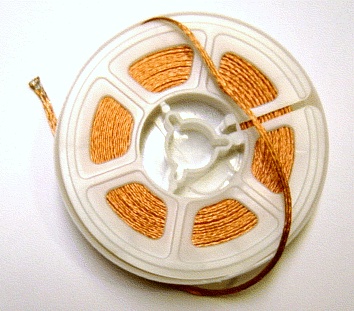
1. First one was to use the braid: You place it on top of the bit you want to remove and you apply more solder on top of it, heating it up. This means that by heating more solder on top of this thread, the extra one will stick to it and you will be able to remove it.
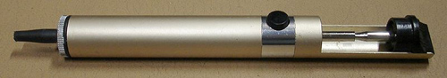
2. Using the desoldering pump: You heat the extra solder that you want to remove and you suck it out with the tool.
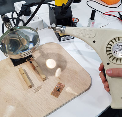
3. Heat gun: You hold the piece that you want to desolder and then you apply the Heat Gun in that position to detach it and remove the piece. Make sure to have the proper tip for not applying the heat to all the board. I also tried to remove extra parts with braid, adding some solder on top of it and applying hit.
*As I was getting more experience during the weeks soldering and desoldering, I realized that some small components can be directly desoldered by applying the heat quickly in both ends and pushing it away.
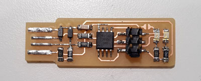
Soldering the final board:
Scheme that I had to follow to place them:
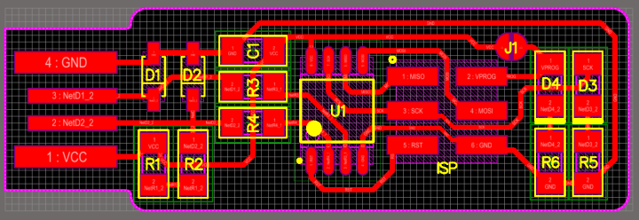
The tutorial recommends to start with the most difficult parts, in this case the microcontroller. Then, I followed the next order:
- ATTiny 45
- R1: 1kΩ
- R2: 499Ω
- R6: 1kΩ
- R5: 499Ω
- D3: green LED.
- D4: red LED.
- D2: 3.3v diode.
- D1: 3.3v diode.
- R4: 49Ω.
- R3: 49Ω.
- C1: 100nF capacitors.
- D1: 3.3v diode.
Turn around the board and:
While I was soldering the components I checked the continuity looking at what connections they had in the red scheme to avoid short-circuits. Once I had all those components in the board I solder the ISP header.
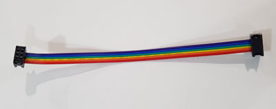
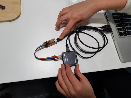
In order to program the programmer I needed another programmer and a cable to connect them. Cable:
3. Programming the ISP:
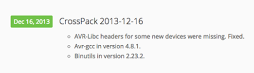
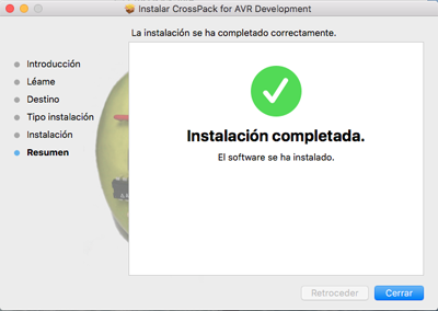
Downlading the CrossPack for Mac:
For downloading CrossPack to my Mac I visited the CrossPack site, I selected the version I wanted to download and then I followed the installation steps.
Then, following the steps of the tutorial, I downloaded the firmware source code and I opened my terminal to access to that file. cd .. --> cd ./Desktop/fts_firmware_bdm_v1
I then build the .hex file that I will use to program the ATTine45 by typing make in the console. Once I had run this command an .hex file was generated in my source code file.
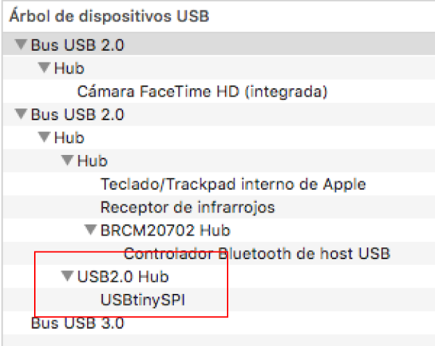
I plugged my board USBtinyISP to the ISP header of the programmer that I will use with the cable previously shown. Then I connected that programmer and mine to the computer's USB. I used an extension cable for connecting my computer with the board.
When I connected my board to the USB port I realize that it was too thin for it to hold properly so I added two layers of vinyl sticker to its back.
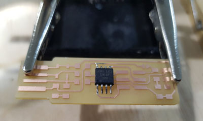
When I connected my board the red light was not shining as it should and after checking tha the USB connection was not loose, I found out that I hadn't solder the jumper (See last picture of the board). I solder it and then I continued with its programming.
With both boards connected I wrote make flash in the console to erase the target chip, and program the flash memory with the contents of the .hex file that I generated.
Then make fuses to set the fuses that control where the microcontroller gets its clock source from. In this step we set all the fuses but the RESET one as for changing this one we need to be sure that the rest is working perfectly (as I won't be able to program it afterwards).
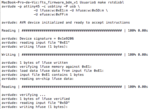
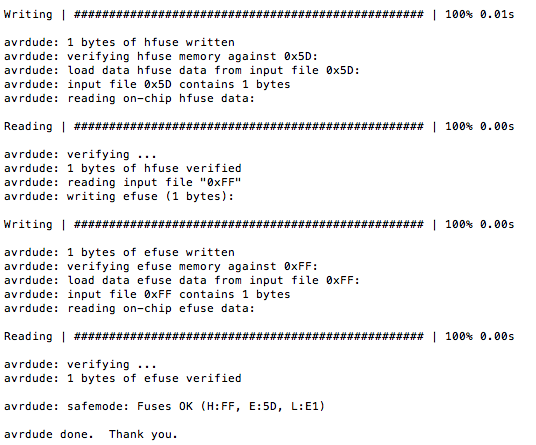
Finally, I had to change the reset pin into a GPIO pin. For doing so I connect the ISP programmer to my board, and I run in the console make rstdisbl. This will do the same as the make fuses command, but it will disable the reset as well.
Final step, desolder the jumper and the board is ready!