Week 6
3D Scanning and Printing
- Test the design rules for your printer(s) (group project).
- Design and 3D print an object (small, few cm) that could not be made subtractively
- 3D scan an object (and optionally print it)
Learning outcomes:
- Identify the advantages and limitations of 3D printing and scanning technology
- Apply design methods and production processes to show your understanding.
Have you:
- Described what you learned by testing the 3D printers.
- Shown how you designed and made your object and explained why it could not be made subtractively.
- Scanned an object.
- Outlined problems and how you fixed them.
- Included your design files and ‘hero shot’ photos of the scan and the final object.
Group assignment:
Group assignment page1. 3D printing:
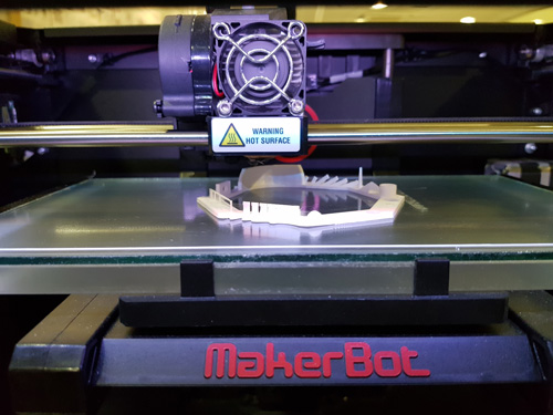
For this weeks assignment I will use the Makerbot 3D printer Replicator 2. 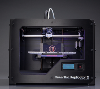
Parameters to consider when designing 3D files:
A. Size of the machine:
The first thing to consider when using 3D printers is the dimension of the machine. In my case the dimensions are: 28.5x15.3x15.5. It is always good to leave a margin on the sides as it is not 100% stable.
B. The objects must be solid
An object being solid means that we have to design a closed volume. For example, we can't print a design of a surface, it needs to have a minimum volume in order to be printed. The machine needs to know what it has inside and outside the body.
C. Normals need to be oriented to the same direction
D. Object has to be no manifold:
An object can not have more than two edges in the same vertex.
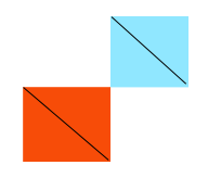 For example, if the previous picture we can see a graphic example, if we put two cubes together, that vertex will have four edges, and when the printer passes through that point to print the second cube, it will think that it has already done it and it will skip it. A solution to that problem is to give a certain width to that union.
E. Avoiding double faces.
If you start a piece from a surface, make sure you erase the surface to export the STL.
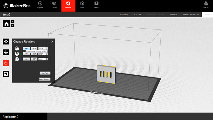
F. Printing orientation:
We have to check how is our figure going to be printed. Sometimes it will set it vertically as default and maybe is better to print it horizontally. We also have to take into account that a 3D printed object will break more easily when applying strength in the direction that it has been printed. An example of printing orientation is the following:
 In order to print holes is better to do them horizontally as if you do them vertically they will have small steps and the unions won't fit as good as they should.
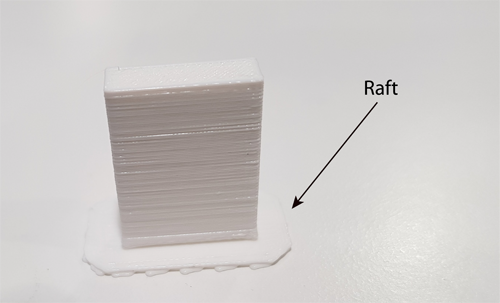
G. Support & Raft:
Sometimes we will need a support to be able to print parts of the body that are floating in the air. The general rule is that object with less than 45º will fall down when they are being printed. You can either design them by yourself or tell the software to do it.
Raft is a base that you can put underneath the figure to un-stick it better from the machine.
H. Divide the model in pieces
Sometimes, when we have a figure that is too big or that it has different angles it is better to divide the figure in small pieces, print them separately and then stick them.
I. Filament's width:
The dept of the material that we can use depends on the nozzel. In my case is 0.4mm. My range of widths for the filament will go from 0.4 to 0.8.
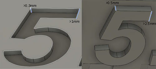
J. Walls depth:
Considering the union between two walls or the width of a wall. In the following image we can see an orientation of the widths that you need to specify in order to cut or pull properly a shape, i.e., for two walls to be separated when is specified.
K. Tolerance:
The tolerance is a parameter that you have to take into account when you are going to join pieces. Is similar to the kerf concept in the laser cutter, but in this case it depends in the characteristics of the surface.
The tolerance is an important parameter when designing the distance between two parts that are being printed together. The tolerance in the X and Y axis will be determined by the filament width and in the Z axis by the height of the layer. Giving the pieces different tolerance levels will make two unions to be:
L. Units:
The .stl doesn't have units. Make sure that the designs are in mm as the machines work with it. Precision of the machine in the X-Y axis is 0.01, and Z 0.0025.
The general rule is that you can't do a floating structure but what you can do is a bridge, a structure that has support on both sides. However the width of the bridge has to be minimum in order for it not to break.
2. Testing the design rules for my printer:
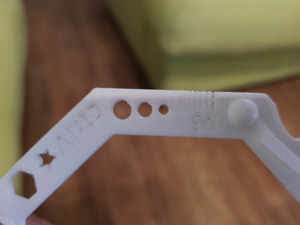
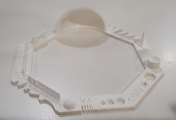
The first test I did for the 3D printer was from a design that was already done. I downloaded it from Thingiverse. You can find it in this link I choose this template as I consider that it was very complete to check the different specifications of my 3D machine.
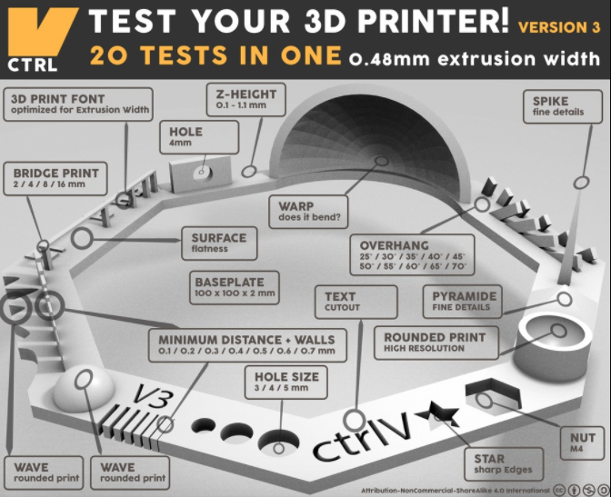
What this template tests is:
- Nut, Size M4 Nut should fit perfectly: I didn't test this one yet.
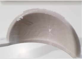
- Wave, rounded print: when you are reaching the top part, there is a bit of distance between one layer and the next one.
- Star, Sharp Edges: they are sharped.
- Name, Complex Shapes: You can distinguish perfectly the letters but they are not cutting the whole objects depth.
- Holes, Size 3, 4, 5 mm: they are about 0.15mm smaller than they should be.
- Minimal Distance: 0.1, 0.2, 0.3, 0.4, 0.5, 0.6, 0.7 mm: 0.7 and 0.6 seem to be the minimum distance that you can leave as the other ones are stick together.
- Z height: 0.1, 0.2, 0.3, 0.4, 0.5, 0.6, 0.7, 0.8, 0.9, 1.0, 1.1 mm.
- Wall Thickness: 0.1, 0.2, 0.3, 0.4, 0.5, 0.6, 0.7 mm. Same as the minimal distance, and also the walls are too thin so execpt for the two big ones the other ones tend to break.
- Bridge Print: 2, 4, 8, 16 mm: they look quite good all of them.
- Sphere, Rounded Print 4.8mm height: Looks good.
- Pyramide, 7 mm height: the top part seems to be a bit more flat than it should.
- Overhang: 25, 30, 35, 40, 45, 50, 55, 60, 65, 70°: they all look good.
- Warp, does it bend?: It doesn not bend but the top part seems to have some loose filaments
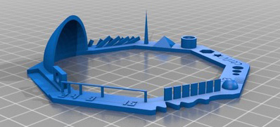
- 3D Print Font, optimized for 3D printing:
- Surface, Flatness: the shape of the numbers is not optimal. Maybe too small.
- Size, 100 x 100mm x 23.83 (10mm width): Mine has this size: 93x91x22mm.
- Hole in Wall, 4 mm diameter, check for proper print: The hole is not perfect, is is more like an elipse than a circle.
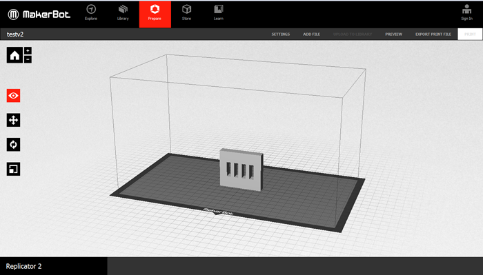
Makerbot work flow:
Once you have the STL file you open the program, MakerBot, and you follow these steps.
- Click on
Prepare Add file, to open our stl file. If the file appears in black, that means that it is not done correctly.- Adjusting the shape:
Select the shape and go toChange Position. You can change it directly by clicking the shape and dragging it or by changing the values of the X-Y-Z. Click onOn platformand onCenter.
Then you can re-scale the shape but in this case I didn't use it as I set the sizes beforehand. I used when printing the scanned object. - Go back to the View button as if you remain in the other ones you will re-scale or move your image.
- Go to settings:
You can save the file with the parameters (.thing).
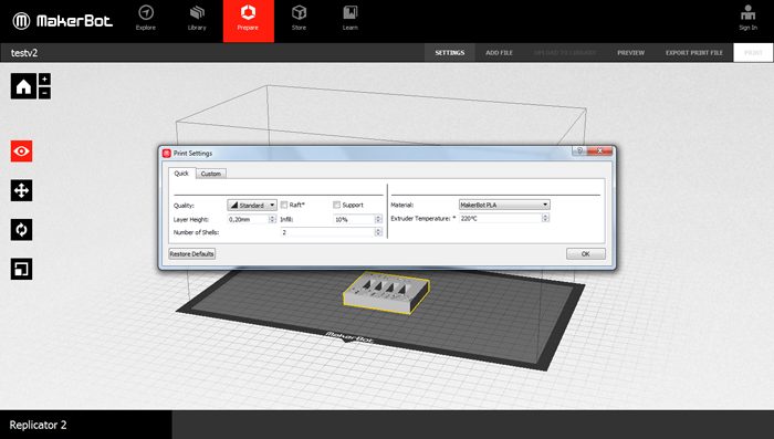
Setting the parameters:
- Before starting, click on the
Restore Defaultsas I don't know what did the previous user modified. - Temperature: you can usually find the range of temperatures of the material in its box, 205º in my case.
- Quality: it will change the layer height. For quick prototypes I choose 0.30 and for normal designs I will use 0.2. As I don't need for now a lot of detail and like this it will take less time.
- Raft and Support checkbox: You can check this boxes and then check in the Preview if it has done them as you wanted or you want to do it by yourself.
- Infill: the more filling that you put, the more time it will take. For normal tests I will use 10-15%. For machine parts 50-60%.
- Number of shells: How many shells you want from the outside part to where the filling starts. The more that you part, the more you put the more resistant the piece will be. For big things Shells: 2 For really thin pieces sometimes is better to put more shells than increasing the percentage of Infill.
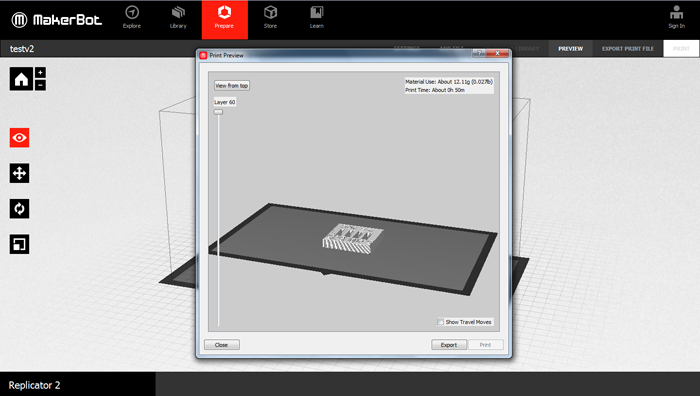
You can either send the file directly to the printer USB or you can export the file, and open it directly in the printer.
In my case I will do it in the second way. I first click on the Preview button to check how does my design look like, the time that it will take and the amount of material (in weight units). You can also see the different layers to see if the shells are right and the Infill percentage too.
Finally, I click on the Export Print File saving the file with short names and in english alphabet. Export as X3G, SD print...
Using the MakerBot Machine:
Once I had the file in the SD card I go to the machine and I follow these steps:
- Put the filament roll in the back part of the machine and then we put the filament trough the tube coming the filament from the bottom part of the roll.
- Turn on the machine from the back part.
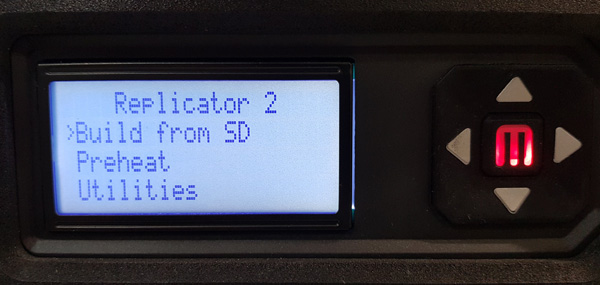
- Then, in the menu you have several options:
- Build from SD: to select the file you want to print (first image).
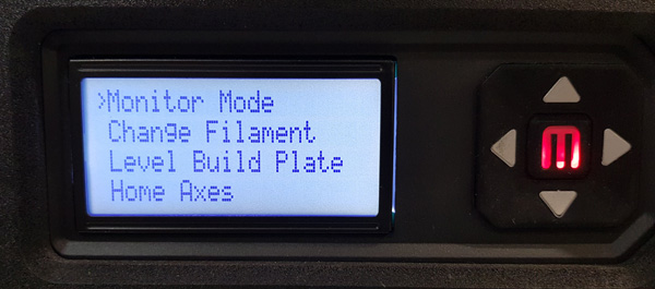
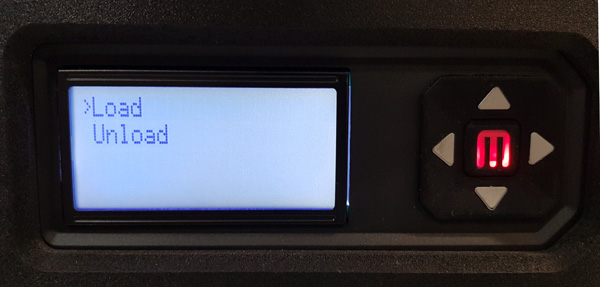
- Utilities: there you can find the setting toChange the Filamentwhere by clicking theMbutton you appear in theLoad/Unloadmenu (second and third image).
- Before starting to print is a good idea to take out the base of the board to put some hair spray for the piece to fix better.
- Once you have the filament in and board ready you choose the
Build from SDoption, you select the file you want to print and you click theMbutton.
3. Creating a test design for the 3D printer:
Designing a figure to test width unions:
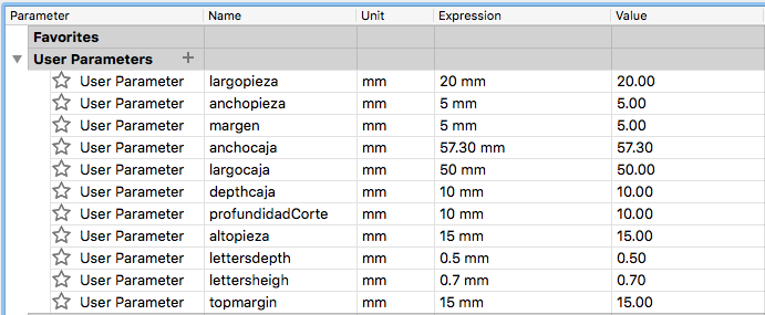
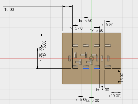
I designed a parametric square piece of 15x20x5 mm and I wanted to test what was the optimal width that I had to give the holes in order for it to fit with another piece. As you can see in the sketch, I gave 0.10mm more in each hole.
Another thing that I was interested in testig was the the different tolerances of the printer when printing letters with volume or by adding some depth on them.
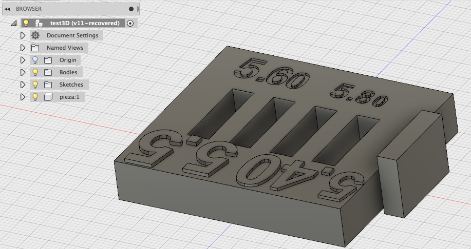
Exporting STL file from Fusion 360:
In Fusion 360 we have three ways of creating the STL file:
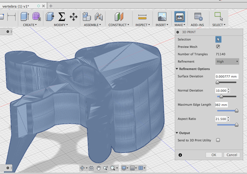
Make -> 3D printing File -> 3D printing Save it as STL. This one will give you the option to format it as binary or ASCII. Binary you won't understand it but it occupies less space. In the ASCII format you can open it and see the vertex. In general it will export it as binary.While saving the STL you can preview the Mesh. The number of triangles will change depending on the body you are saving. The Refinement can be modified (low, medium, high and custome). In general we can choose high, but sometimes if the mesh is not adjusting properly or the machine that we are using has a higher resolution we can change to costume and modify the parameters:
- Surface deviation: if you give a low resolution, your shape will be more polygonal. The more triangles that you give the more resolution you will have. It will change how much your shape will differ from the original one. In our machines is 0.01.
- Normal deviation: it points to the inside and outside part of the shape. That parameter gives you the angle between one triangle and the other. The smaller it is the more resolution you will have.
- Max Edge length: If the edges are very long the machine won't do it properly. For really long shapes it is better to reduce this length. Between 6 mm and 3 cm.
You can also export the file to a software that can work with this file.
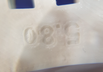
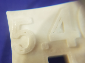
Results of the second test piece:
I had several mistakes when designing this piece:
The first one is that when I was establishing the measurements, I thought about the offset in the depth dimension, but I didn't in the heigth. This means that when I went to introduce the small piece in the wholes to analyze what union was going to fit better:
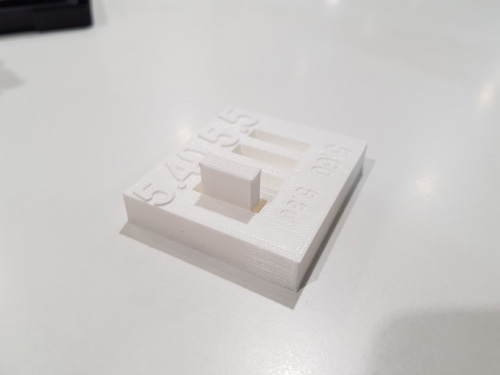
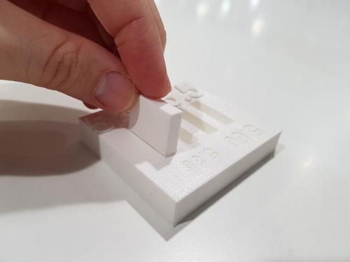
I gave the numbers some bigger and smaller sizes than the minimum ones for walls to have the propper depth. Te result is that the bigger numbers you san see them correctly, whereas the small ones they have some small holes, or the shapes are not defined properly.
Individual assignment:
1. Designing and making a 3D object:
I designed several objects that could be printed in 3D and that could not be made substractively because I didn't have a clear idea at the beginning.
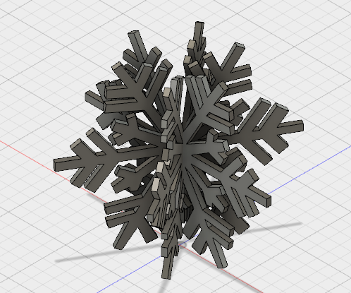
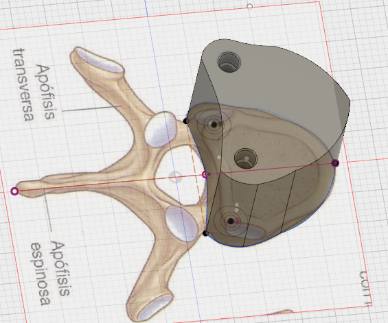
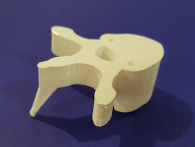
Designing a 3D vertebra
But then thinking about the posture corrector that I want to create for my final project, I started to design a vertebrae with the idea of puting some of them together in a solid structure. This structure will give stiffness to the back. The idea is to create a union like this:
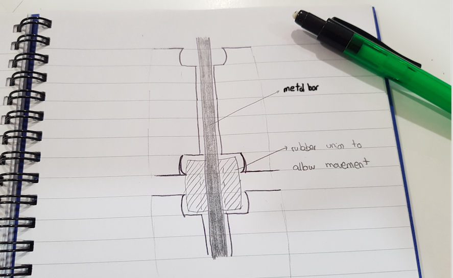
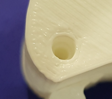
The overhangs of this unions can not be done with any ofther machine. The idea is to have a hole that will allow the metal bar to cross the different vertebrae, and then a bigger hole with overhangs that will have inside a elastic union that will also be 3D printed with elastic thread.
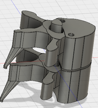
For designing the vertebrae, I downloaded an image from this site and I used it initially as a canvas. I started from the right side body that you can see in the pictures and as I will join one vertebra with the other I needed to create a union hole that can not be done with other machines.
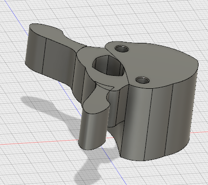
The vertebrae will be joined together with a metal bar and the unions will have a rubber cylinder that will allow some flexible movement. The results of this par of the design are shown in the next pictures:
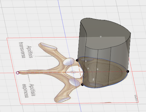
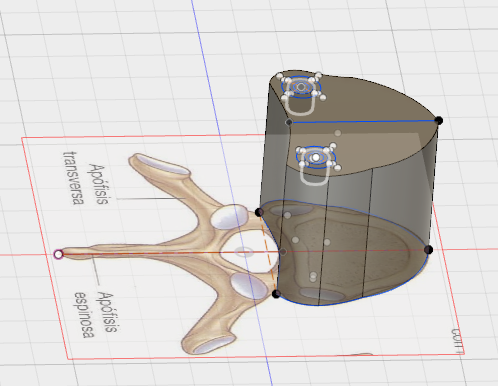
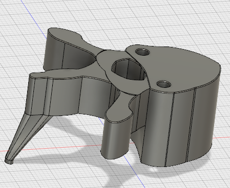
Then I continued designing the other bodies of this structure, sketching one of the transverse elements and then mirroring it with the central axis. Then I designed and sketched the Spinous one, creating an offset plane in order to do the low part of the piece.
Exporting the file in fusion:
To export the .stl file from Fusion you can do it in several ways. I choose to click on the MAKE button in the top menu that it oppens directly the 3D printing menu. There you can choose the quality that you want your piece to have. In the next pictures you can see the process I followed to export it.
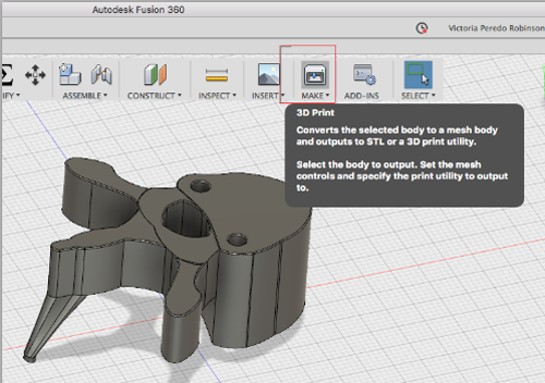
Once you click the OK, a window will pop up to ask you where do you want to save the .stl file.
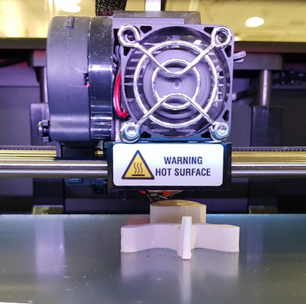
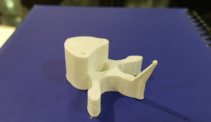
Printing the vertebra:
The first test was to print one vertebra in a small size to see how the final piece will look like.
After doing so I created a new component from the previous bodies to be able to print two. Then I did the union between them that will give them an axis to move and rotate.
2. Scanning:
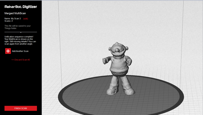
MakerBot digitizer:
The first machine that I used to scan was MakerBot digitizer, which is a desktop tool that enables you to turn physical objects into 3D models.
Before starting the first thing I did was to calibrate. I went to Settings->Calibrate cameras. Then the software tells you how to place the calibration object. First putting the A upwards, then the B and finally in order to calibrate the lasers you take out part of the object and you center it in the machine.
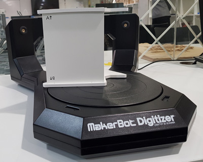
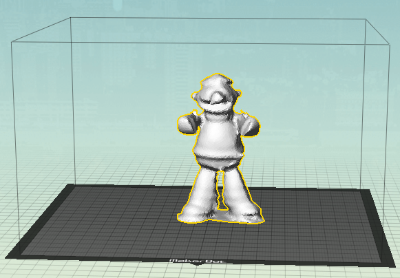
Once it was calibrate it I placed an object in the middle:
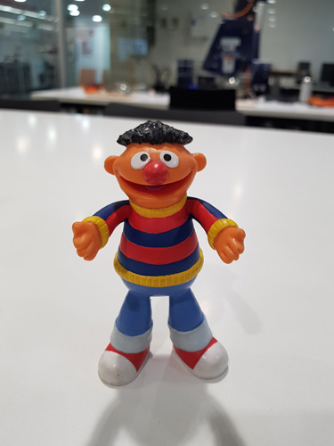 First time I scanned it, I was 3D printing in the same table so as the object was not completely static the scan didn't work out correctly. I waited until the printer finished and then I re-scan it again.
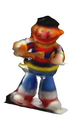
Sense 3D
I also tried scanning with the Sense 3D machine. This one differs from the previous one that instead of being the machine who is moving and turning around the object, it is you who has to hold the machine and turn around the object. This machine enables you to scan bigger things than the other one does.
My first attempt to scan an object with this tool was the following: (As you can see I moved while scanning so it didn't get the shape correctly).
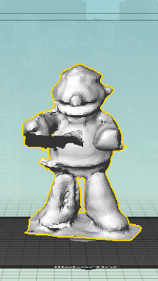
The previous scan I did it by moving the platform where the object was standing and moving the 3D Scanner. With this technique I didn't get very good results so I tried by moving the scan around the object and it worked out much better. These were the results that I have obtain. Once you have this preliminary shape you can adjust the shape in a design program.
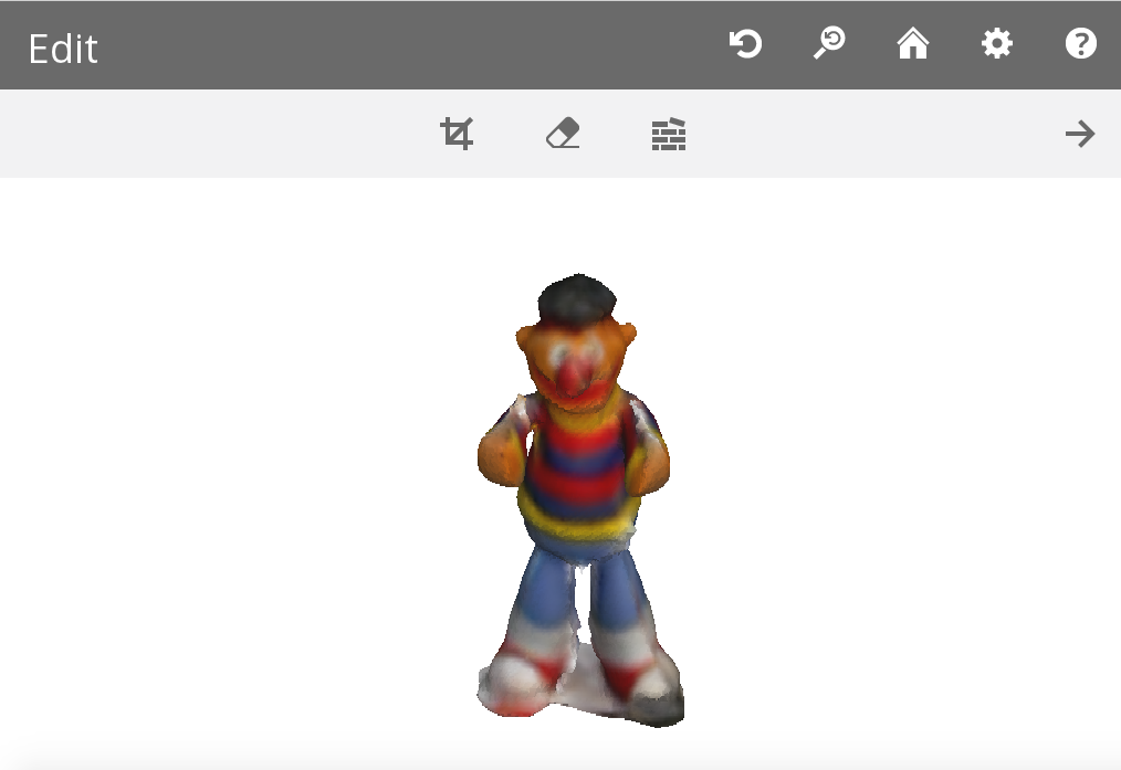
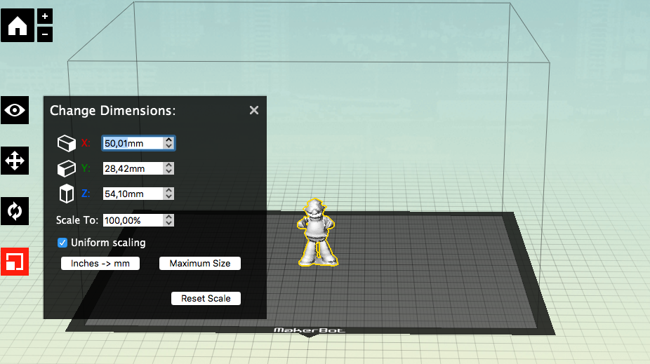
With the .stl file of my object. I opened in the MakerBot software to print it. As the real size is quite big I used the re-scale settings to make it a bit smaller.
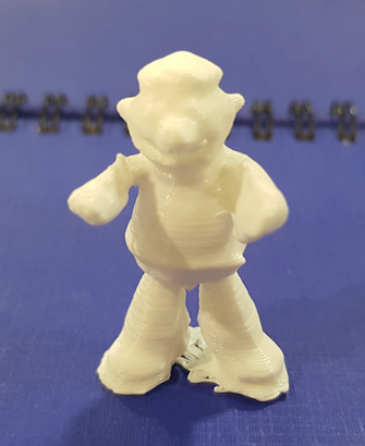
Final result of the object printed in 3D:
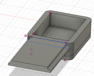
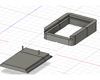
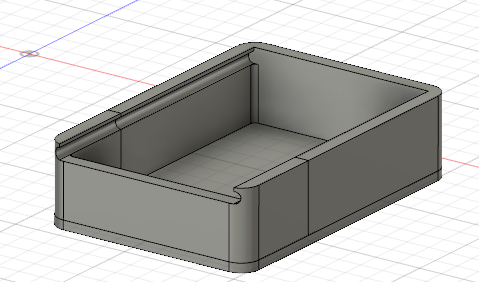
Box for the thread board
On Week 3 I did a design of the container for the thread board that was a simple box sourounding the board and the battery. But this box needs a number of specifications to work properly:
- Sliding lid to open and close the box
- Space to extract the battery to charge it. (For this first prototype it will be set like this, in future approximations a charger connection will be included in the box)
- Space to be able to extract the board in case I need to reprogram it.
- A layer of separation between battery and board.
- Holes to attach the board to the separation layer so that it doesn't move.
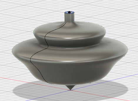
Rail type I:
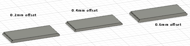
I first tried different designs to test the type of lid I will include to open and close the box. My first approach was a spheric one.
With the same sketch that I did this rail cut I extruded what will be the lid giving it different tolerances by offsetting the sketch. I tried with offsets of 0.2mm, 0.4mm and 0.6mm. This means that they will have a total difference in the unions of 0.4mm, 0.8mm and 1.2mm respectively.
This time I decided to try with NinjaFlex thread as it will be more confortable to 'wear it' on the side of the t-shirt. For doing so I customize the settings on the Makerbot software settings:
The result of this test was the following:
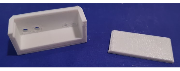
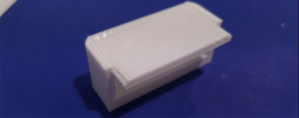
Rail type II:
Appart from being too small the rail this shape was not giving it a great stability so I tried with a different shape including an end union that will make both pieces attach better.
The result of this test was the following: