Week 8
Computer-Controlled Machining
Group assignment
Individual assignment
Learning outcomes:
- Document the process of design and production to demonstrate correct workflows and identify areas for improvement if needed.
Have you:
- Explained how you made your files for machining (2D or 3D).
- Shown how you made something BIG (setting up the machine, using fixings, testing joints, adjusting feeds and speeds, depth of cut etc).
- Described problems and how you fixed them.
- Included your design files and ‘hero shot’ photos of final object.
Individual assignment:
1. Introduction to CNC machining:
As I don't really know this machine I did a bit of research on the basics so I will start by answering two questions: What is a CNC cutter? How does it work?
What is a CNC cutter:
A CNC, Computer Numerically Controlled, machine is a machine that uses a cutting tool that by rotating at a very high-speed removes material from a part. Apart from being bigger than the Laser Cutter that I used in the 3rd week, i.e. you can cut big things, a main difference between this two machines is that you are able to cut the material with different depths.
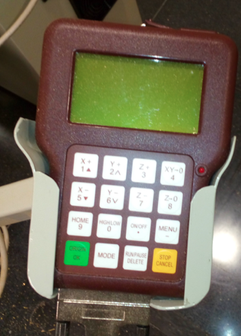
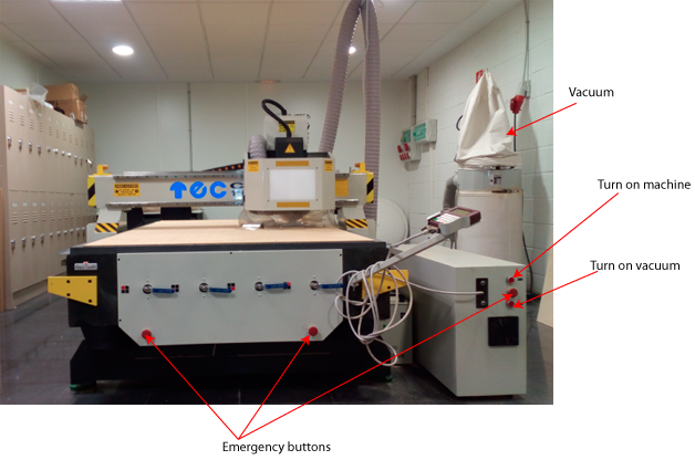 On the right part of the machine you can see three red buttons, the top one is to turn on the machine, the bottom one is to turn on the suction. There are two emergency buttons, one is positioned in the middle of the ones I described previously, and the other one below the blue handles that you can see. These blue handles control where the suction will be on.
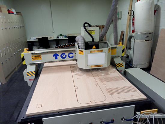
Then on the right side you can see the vacuum that will remove all the wood chips generated when cutting.
Below the board there is a sacrifice layer that will prevent both the tool and the suction plate from breaking.
How does it work:
Link. The machine reads a pre‐programed computer file telling it where and how to cut. A cutting bit is rotated at a very high RPM by a spindle motor, which can move the bit up and down. This mechanism is moved left, right, front, and back by a cross arm. The machine is therefore known as a three‐axis router because it can move on the XY & Z axis. The machine can do two dimensional cutouts and etching, as well as three‐dimensional relief work.
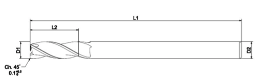
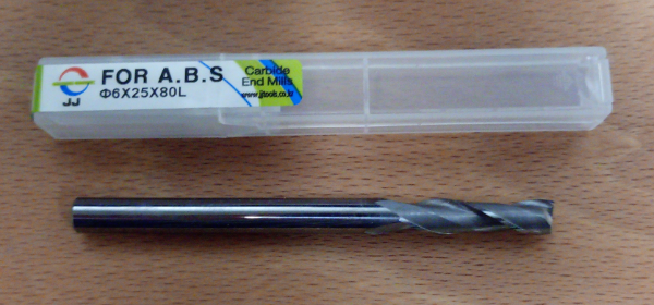
Parts of the tool:- L1: total length of the tool.
- L2: Cutting length of the tool, we usually choose one that its similar to the thickness of the material.
- D1: width of the cutting section.
- D2: with of the tool. Sometimes is not the same as the width of the cutting section.
 Tool clasification:
- Up-cut: they extract the wood chips to the top, they do smoother works in the lower layers.
- Down-cut: opposite, they have a better finish in the top layers.
- Mixed: they combine both techniques, they are more smooth in the middle.
- You can also classify them by the number of cutting edges (1-8). I will use ones with 1 or 2. High ones are for metals.
2. Computer Aided Design (CAD): Designing a TV support:
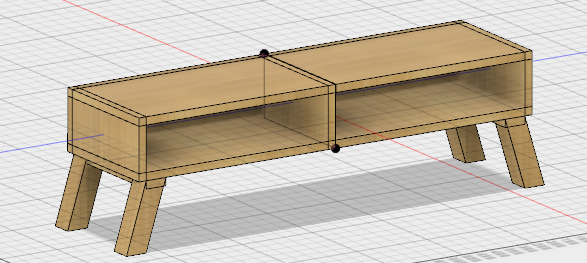
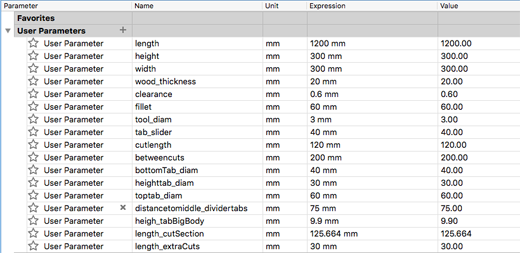
For this week assignment I wanted to create a TV stand. By searching online I found some nordic style ones that I really liked so I was inspired by them to create my design. The first approach that I did was the one you can see in the next picture, that is a simple square TV stand that could be made by cutting the lower, top, and side parts and joining them together. I did all my designs parametric in order to be able to change the sizes if it was necessary.
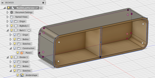
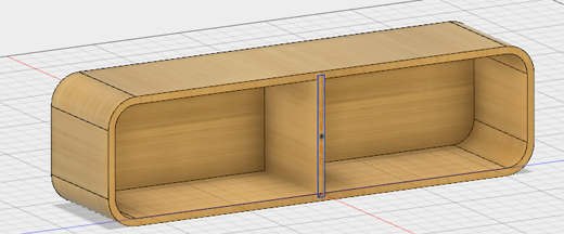
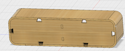
But I was not convinced, so I started a second design. I thought that it would be nicer with smooth corners, so I did a chamfer. I added some extras, like the doors, and the inside selves with different heights.
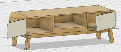
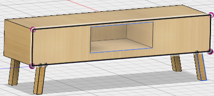
PROBLEM with this design:
The problem that I had with this design was that, as you can see in the previous work flow, I first created the big components and then I did the different sketches over if for doing the inside drawers and selves. I created all the components and then, the last thing I did was to chamfer the corners. By doing this the curvature was only on the outside part of my figure, not in the inside, so could not separate the back part in order to export tis profile. So, as I was feeling quite stuck, I decided to start again from scratch, establishing the correct measurements and doing the components thinking previously how they were going to be cut.
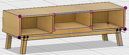
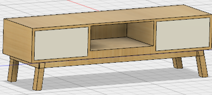
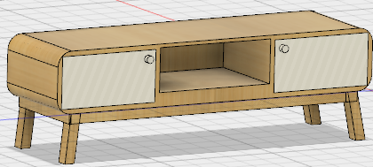
Final design of the TV stand:
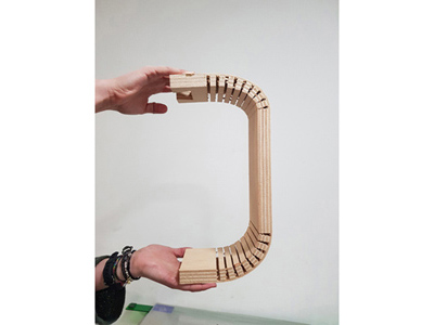
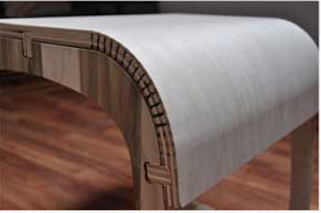
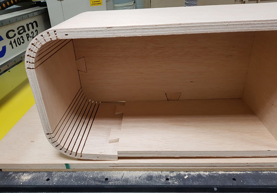
So, with previous knowledge of how I wanted to cut the different pieces, I re-did the design. I sill wanted to do curve edges and I will use the Kerf Cutting technique that I introduced before to do so. This technique consists in doing some longitudinal cuts in the wood that allows it to bend. Here you can see an example of this technique in a stool:
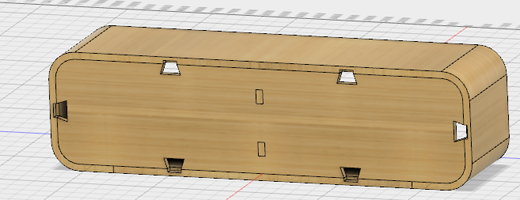
How I created the joins between the components:
To be able to fit everything in my board 2400,1200mm I decided to do a big cut with almost all the main component, joining it with a square board on the bottom.
Click here to download design of the tv stand .f3d file.
Creating the .dxf of the main component
PROBLEM when exporting the bended part:
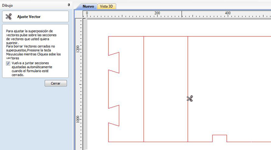
As I wanted to create a curve object I had to, once I had designed the stand, unbend it in order to be able to export it in 2D. I found that quite tricky, I tried with an extension that you can add in Fusion 360 Exact Flat, but I was not able to installed in MAC, I kept on having an installation error. I tried to install it in the Microsoft virtual machine that I have, and I was able to install it but when I used this plugin I didn't get the result that I wanted.
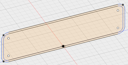
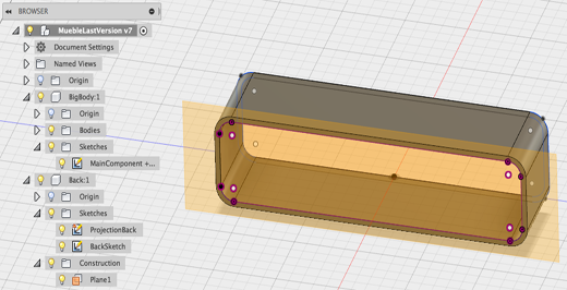
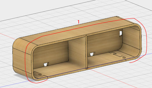
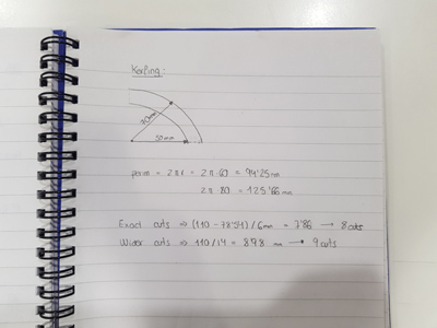
So what I did was, sketch the parts that were flat like the back part, the divider and the bottom part; and then for the big one, I first projected the flat top part, then I drew the cuts on another sketch, putting it together, and then the side part. The calculations for the number of cuts in the kerfing are shown below.
3. Computer Aided Manufacturing (CAM):
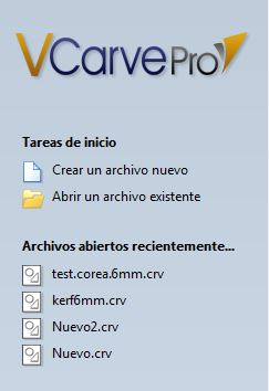
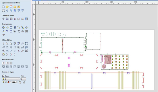
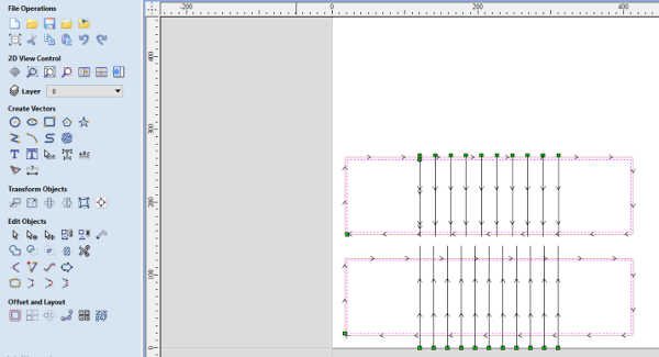
Working with VCarve:
I will explain the process to follow in VCarve in order to prepare the file that you will send to the machine with the cutting test that I did.
- Create a new File.
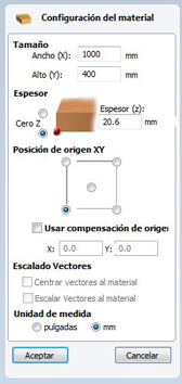
- Set the size of the material (2400,1200mm), the thickness (20mm), the position of the origin (low-left) and the units (mm).
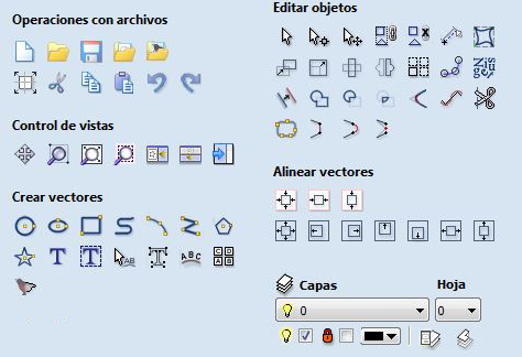
- Once you have set this parameters the main window will open and there you have different tools to work with your drawing.
- I imported my file that I didn't need to modify the design, and I had to move it to the board.
- Check that you don't have open edges,
Edit->Select all the open vectors. - Check that there are no duplicated vectors,
Edit->Select all the duplicated vectors.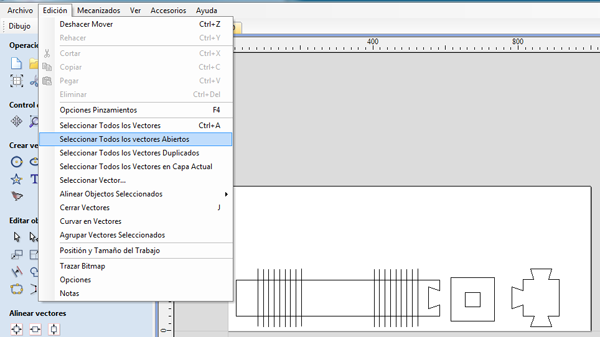
- You can then create layers to have your components organized. For example you can create a layer for the interior cuts and another one for the outside ones.
- Click on
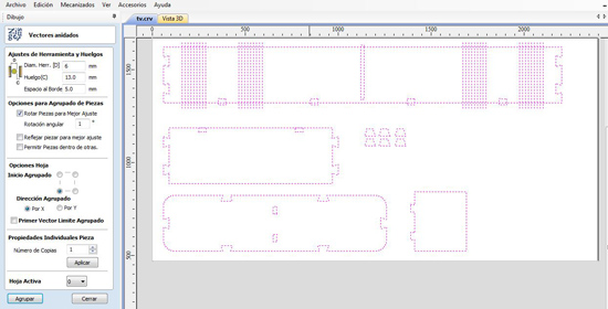
netsfor the software to relocate the different pieces. Before doing so is a convenient togroupthe different components of a piece (interior+exterior), for the program not to separate them when nesting them. You will have several options when you click on nest.
- Tool diameter: to leave that space between the different cuts. - Once you have them in good positions, you undo the grouping of the components. You can then see that the interior and exterior layers are in different colours.
- Adding dogbones: First you specify the diameter of the tool, and then you place them in all the interior edges. There are three types of fillets or tool radious:
- Normal fillet: to chamfer the outside edges. It doesn't need to be a big fillet but it avoids the machine slowing the speed when going cutting 90º edges. In our case we gave it a value of 0.5 mm.
- Dog-bone fillet
- T-bone fillet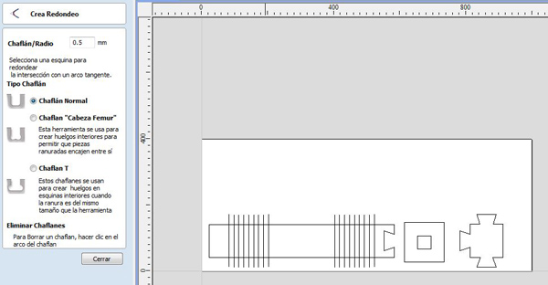
- Preparing the toolpath:
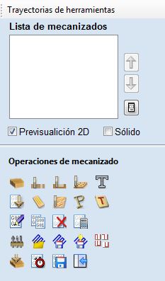
A. With the first button that you have you define the thickness of the material 20 mm. If you are not going to change the tool, you can select to make the zero on the bottom; if you are planing to change it is better to do it on the top as you are not going to move the wood board to do the zero for changing the tool. We don't modify the secure Z either the origin position.
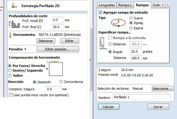
B. Profile toolpath: You set the height where you want to start and finish; to cut the whole way through (0, 20).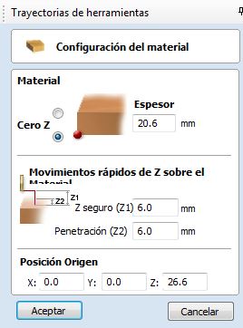
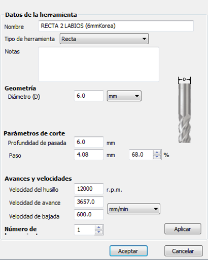
- Selecting the tool: you open the tool selection menu and the ones that you can use will appear. In this case we used the 6mm Korea. Once you choose it you can then click on edit and change the parameters.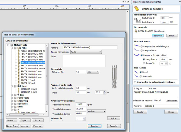
- Once you have selected the tool you can edit the parameters, in my case I set them as:- 6mm Korea tool
- Pass depth 6.0 mm
- Stepover: 3.0 mm
- Spindle speed: 12000 r.p.m
- Progressing speed: 3657
- Plunge rate
- Leave the compensation parameter as it is.
- Ramps: zigzag 20º
- Tabs: extra bits that are added to the piece for it not to move when the tool finishes cutting. You click onEditand you can either put them wherever you want or you can set them automatically. I will use the automatic way but checking it they are where I want them to be.(10;1'2).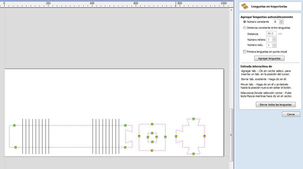
- Select the vectors that you want to cut, first the interior layer (Just the open vectors and you select the layer that you want).
- Set a name and click on calculate.
- When it finishes calculating you can have a preview.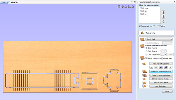
C. Saving the file of the preview. Format (G code(mm)(.tab)). For different tools you will have to save it separately.
Clearance: distance between the end of one piece and the other one. So this distance is twice the tool diameter + the space you want to leave, usually 10mm plus diameters.
- Allow or not to do mirrors or to turn around pieces.
- Allow to put pieces inside other ones.
*For creating the same trajectory that you had done previously you can copy it and then edit the parameters that you need to modify, or the layers that you will be cutting.
Preparing the Final TV stand file for the CNC:
I included all my components .dxf in Illustrator in order to export the .dxf with all of them together (as the main one I had to join different parts together I found it easier to do it in Illustrator).
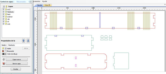
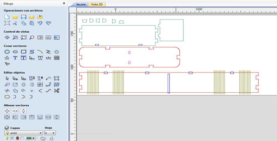
Following the previous steps I created a new file where I opened my .dxf file. What I did was to separate the different cuts that I had to do in different layers, i.e, putting the exterior parts in one, the interior holes in other, and the undercut in other one.
This time I had to fix some problems:
- Some of the lines were duplicated:The main component, the top orange one in the picture was the result of joining the projections of the individual parts (as is a round object I did it like this and not exporting ir all together like the other pieces), so the edges where two parts were joining were duplicated.
- Furthermore, some of those lines didn't need to appear.
- The cut lines that will make the wood bend were not joined so I had to right-click on them selecting the parts and join them.
Next thing I did was to display the objects in a more efficient way. As the first piece that I was going to cut was the big one, I placed it closer to the origin of the board.
Then I did the dogbones in all the 90º edges, the interiors and also in the sharp angles. Once I had that done, I planed the different trajectories to cut the objects. I did it in two steps, first the big component and the back part to check that they join correctly and then I cut the rest.
Different toolpaths
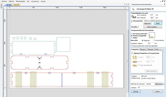
1. Cuts for kerfing
The first trajectory was the cuts for the kerfing. To make sure that the cuts were performed the correct distance we put a ramp at the begining and also at the end of the cut. The depth of this cut was 17.6 mm (out of 20mm of the material).
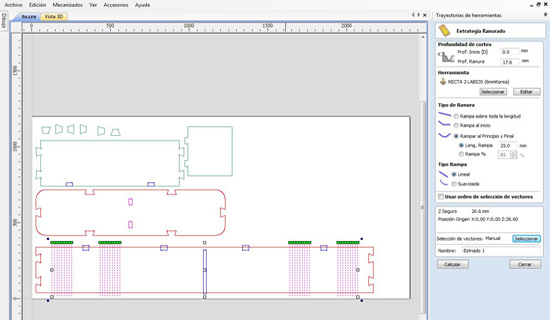
2. Interior cuts
The second toolpath was the one that will perform the interior cuts. These interior cuts are located on the back piece of the furniture and conform the join with the separation piece. In these case we set the pass depth to 20.6mm.
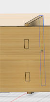
3. Pocket toolpath
The union between the big piece and the back part was not a whole way cut. In order to do so I performed a pocket cut. The layer that I cut with the pocket toolpath was the dark blue one that you can see on the picture; on the top part of the main piece and the hole were the separation piece will be inserted. This description gets a bit more clear when you see the asambling pictures.
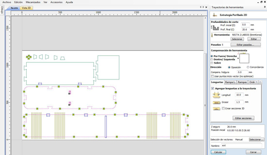
4. Exterior cuts
The last cut was the exterior part of the pieces. I also added ramps and tabs for this cut as was explained before.
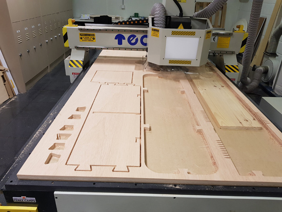
As you can see on the images I first performed the cuts of the back, the main part and the small union pieces in order to check that everything fitted. Once we checked that it was correct I cut the bottom piece that puts together the main part; and the separation piece. These two components have two types of cuts, pocket toolpath for the unions of the bottom with the back part and exterior cut.
4. Machining the Design:
Workflow of the CNC:
- Prepare the file.
- Take it to the machine in a USB.
- Turn on the machine: When you turn it on it will ask you if you want to go home, you press
OK/HOME. In this case you press this button to say 'ok', but in general theHOMEbutton is the users home. - Turn on the vacuum holddown system.
- Before cutting you also need to turn on the dust collector.
- Move the head by pressing the
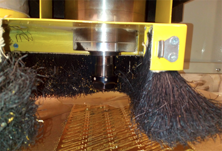
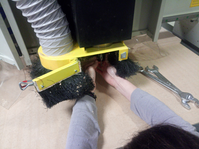
X+/X- and Y+/Y-. - Colocate the tool: You first out the clamp in the head, and you screw it a bit, and then you insert the tool. Its important to put it correctly, not to inside not to outside. When you decide the X0/Y0 position you press for a few seconds the
XY-0button to set the users zero. - Turn on the suction.
- Calculate the zero of the board. For doing so you have to press at the same time the
ON/OFFand theMENUbutton. If the tool starts to turn around means that you didn't press both at the same time or that you didn't release them at the same time. In that case, click on cancel and do it again. You put the metal piece on top of the wood and the machine will go down until it touches it and sets that Z0. - Send the file.
5. Final result
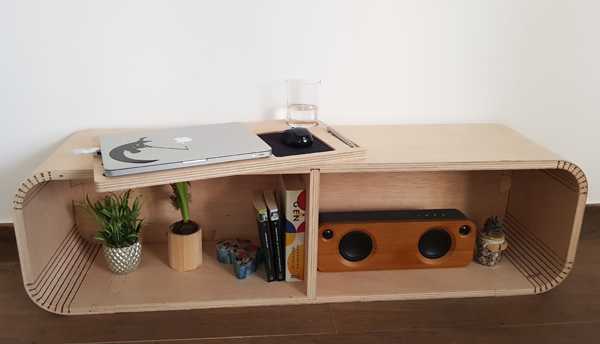
After cutting all the pieces it was time to put them all together. We had some issues with some of them, the middle one with the top one for example, as the unions were not wide enough so we had to sand them a bit. Order to join them:
-First the big one with the cuts (round one) with the back one.
-Then the middle divider.
-And last but not least, the bottom one.
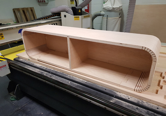
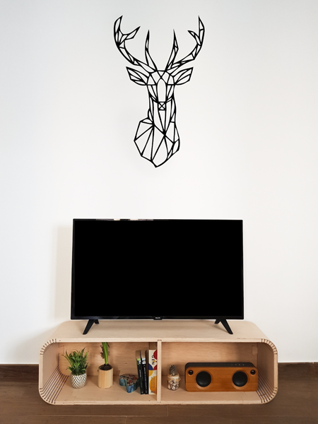
So, this is the final result of my TV stand!
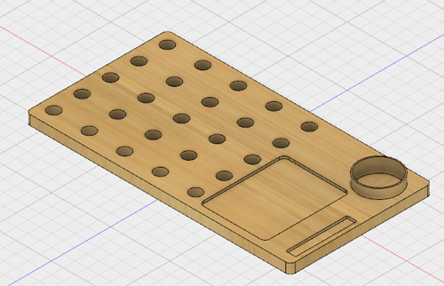
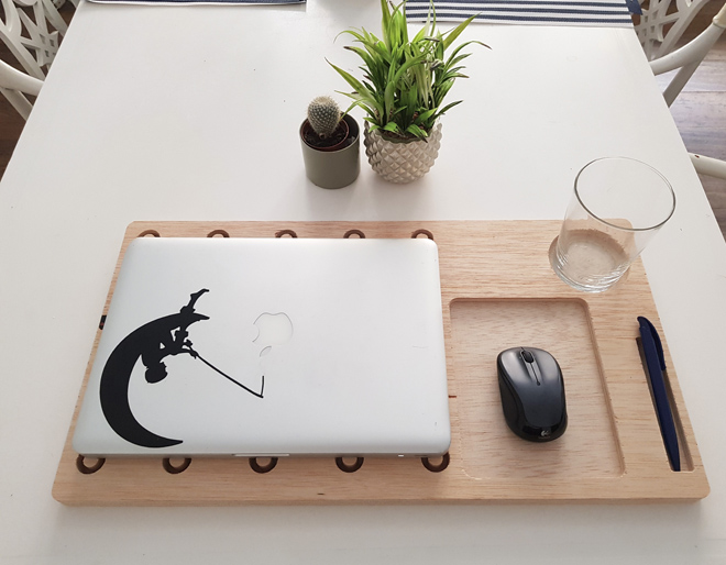
6. Creating a computer tray:
As I still had some wood left and sometimes I like to work in my livingroom sofa, I wanted to create a computer tray. The main problem when working in the sofa is that you can not use the mouse properly, so I wanted a tray that had some holes in order to ventilate the computer, mouse pad and a small cut to put my cup of coffee or my glass of water.
For cutting this tray I also performed three of the previous cuts that I explained before.
- Interior cuts: in order to add some ventilation on the tray for the computer and also to make it lighter I added some interior wholes. I placed some tabs that I actually liked how they looked like so I left them once cut!
- Then I did the pocket toolpath for the mousepad, the glass and the pen components. In this case I cut 1cm down.
- Exterior cut: the last cut was the exterior cut, in the same was as I did them before.
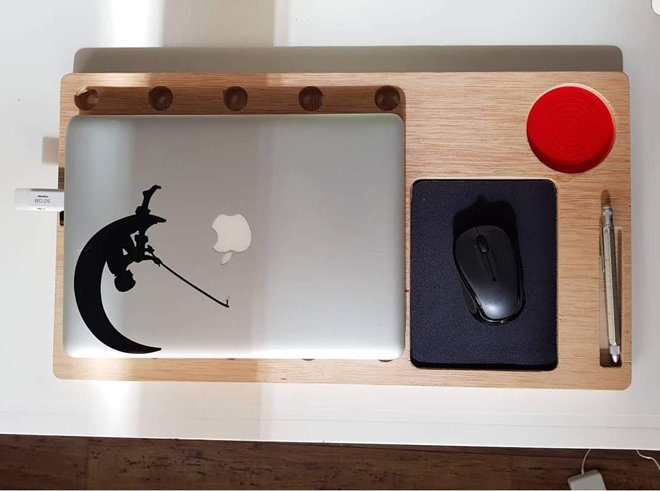
Final result:
This was the result of my tray. I ended up taking out the ramps of the interior cuts and I added a mouse pad and a methacrylate base for the glass.
Group assignment: Group assignment page
As part of the group assignment I performed some tests that will allow me not only to do the correct kerfing to bend the wood in my TV stand but also to create the joins with the right sizes:
| Tool diameter | 6 mm |
|---|---|
| Depth of the cut | 6 mm |
| Step | 4.08 mm |
| Spindle speed | 12000 r.p.m |
| Feed Rate | 3657 mm/min |
| Plunge Rate | 600 mm/min |
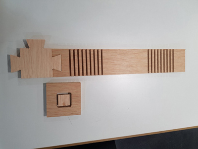
Testing how to do the kerfing to bend the wood
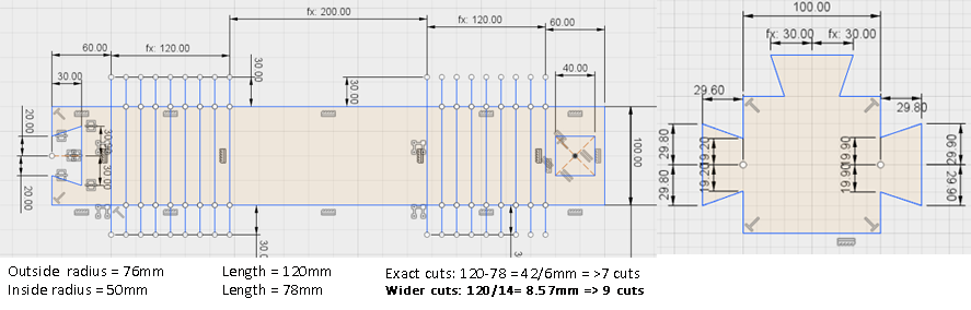
For testing how to bend the wood I designed a piece with cuts that is actually the side part of my furniture. In the next pictures you can see the sketch with the cuts, and the shape that I am saying I wanted to obtain.
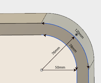
I wanted to have a 90º angle in my bending, and to do so you have to measure the outside (120mm) and the inside perimeter (78mm) of the curve.
Then, you need to do a number of cuts (with the corresponding width, the diameter of the tool) that makes that 120 mm - > 78mm by making cuts.
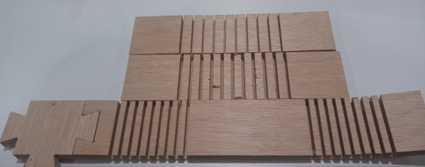
I did three kerfing tests: the two first ones with an outside perimeter of 170 and the final one with 120mm of perimeter.
- 170mm of outside perimeter with 10 cuts, being the width of the cuts the one of the tool.
- Eleven wider cuts over the same distance as the previous one.
- 9 cuts over a perimeter of 120 mm. This perimeter corresponds to the one that I was using on my TV stand so, once the previous tests were performed I did a this one as the final one.
Test the tolerance
I included a 40x40mm square in order to measure the tolerance of the machine.
Testing the tabs width
I also included the tab that I will use for the joins in my furniture. The real size of that tab is 60x40x30mm, I added two more tabs that were 0.2 and 0.4 mm smaller to see which was the optimal fit.
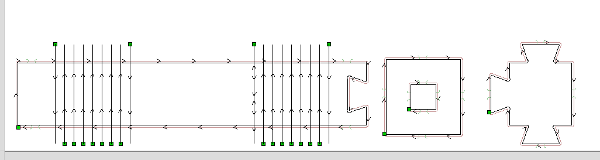
Milling the test pieces with the CNC
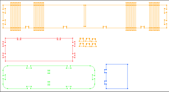
I cut these test parts with the 6mm tool. In the next picture you can see the three trayectories that I performed, the exterior, interior and the kerfing one, following the same steps that I have explained before.
Results:
ToleranceThe test shows that when you cut the square, having an original size of 40x40mm, the size is reduced by 0.2 mm in all of the sides. I also observed that the last side that was cut, was not 100% straight, it had a bit of an angle. That could be caused by the strength of the tool, moving this small piece to the other side.
Tabs testing: I found out that the optimal width for my tabs is 0.4 mm more than the width of the join.
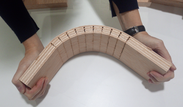
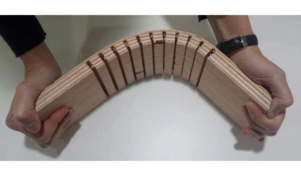
Kerfing: In the next picture the three tests can be observed. The top one correspongs the the tight cut, with ten 6mm width cuts. The one underneath with eleven wider cuts and the bottom one is the final test with the distance of my furniture and 9 cuts.
These results showed that when you do the cuts with the tool width, 6mm, the wood bends but is not optimal, is too stiff, whereas the second test with wider cuts is easier to bend without loosing stability.
With these tolerance, joins and kerfing final tests I did the corresponding design that was explained during the individual assignment.