Week 9
Embedded Programming
Group assignment
Individual assignment
- Read a microcontroller data sheet.
- Program your board to do something, with as many different programming languages and programming environments as possible.
- Optionally, experiment with other architectures.
Learning outcomes:
- Identify relevant information in a microcontroller data sheet.
- Implement programming protocols.
Have you:
- Documented what you learned from reading a microcontroller datasheet.
- What questions do you have? What would you like to learn more about?.
- Programmed your board.
- Described the programming process/es you used.
- Included your code.
Individual assignment:
0. First steps when programming my board:
I did the first steps of the programming on the Week 07 assignment. Click here to go to that page.
1. Fundamentals:
Before starting to program the board is important to have some knownledge of the components and microprocessor you are using and the specifications that it has. For doing so you have to read its datasheet, in my case the one of the ATtiny44 extracting the main information of it. A fundamental thing is to know what pins do you have in your microcontroller and where have you connected the components that you will work with. I connected my two LEDs and my button in this way:
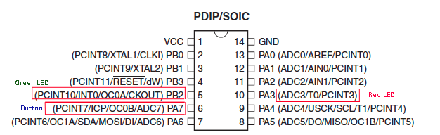
- VCC: supply voltage.
- GND: ground.
- Port B (0-2): Port B is a 4-bit bi-directional I/O port with internal pull-up resistors (selected for each bit). Port B pins that are externally pulled low will source current if the pull-up resistors are activated.
- Port A (0-7): Port A is a 8-bit bi-directional I/O port with internal pull-up resistors. The same as port B, they will source current if the internal resistors are acitivated.
- RESET: A low level on this pin for longer than the minimum pulse length will generate a reset.
- MOSI: Master Data output. Slave Data input for SPI channel.
- MISO: Master Data input, the data comes into our microcontroller through this pin.
All the pins, but the GND and VCC can be used as I/O. Some of them have secundary uses; for example, when you want to connect the SPI some of them will need to have an especific function, but the rest of the time can be used for other things.
"ATtiny24A/44A/84A are low-power CMOS 8-bit microcontrollers based on the AVR enhanced RISC architecture":
That's one of the first sentences you can find in the Datasheet of the ATtiny. I think is important to make clear some of this concepts. I took some information to be able to distinguish them from this site.
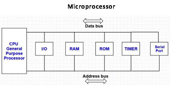
Microcontroller vs Microprocessor:
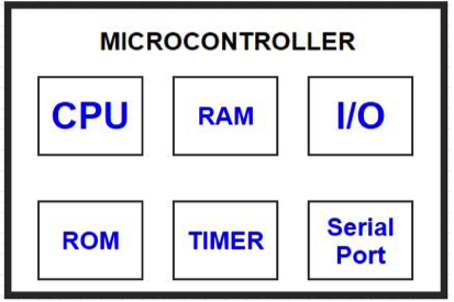
Types of memory:
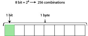
Word size: 8 bit microcontroller:
That sentence also talks about being a 8-bit microcontroller. This means that all the information has to be divided in blocks of 8 called bits.
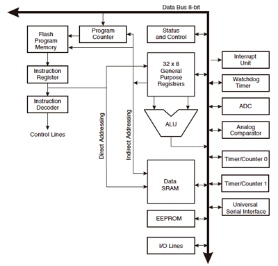
2. CPU core:
ATtiny is based on AVR RISC (reduced instruction set computer) architecture. This architecture is a Harvard architecture, which means that it has separate memories and buses for program and data.
- While one instruction is being executed, the next instruction is pre-fetched from the Program memory.
- The Arithmetic Logic Unit (ALU) can only perform one operation per clock cycle. This unit supports arithmetic and logic operations between registers or between a constant and a register.
- General purpose registers
- Pogram counter: it saves the address of the next instruction that will be executed. This address will be updated every clock cycle.
- Stack: mainly used for storing temporary data, for storing local variables and for storing return addresses after interrupts and subroutine calls.
- Program Status Word (PSW): it stores the bits for the condition operations, the priority of the instructions, the mode that is being used and other control bits. Its important in the I/O control.
3. Operators:
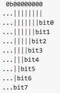
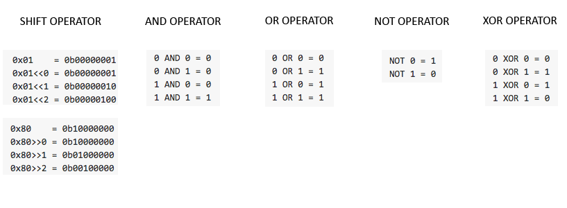
The numeration of the bits in a byte starts from the left. Is important to know that for when you want to modify the registers or send the information.
- SHIFT: moves the position of a factor to the right or left, the number of positions that the second number indicates. << 2 indicates that you are inserting two ceros, i.e, moving the '1' two positions to the left.
- AND: you use AND when you want to set a bit to 0.
- OR: in the opposite way you use OR to put a 1 in a bit.
- XOR: invert a value. For example you can use it to change the state of a let from on to off.
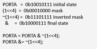
To work with this operators you need to: know what port you are going to modify and to create the mask that will be the 'function' that will change your value as desired.
An example of this process can be this one: You want to put a 0 in the bit 4. For doing so you create a Mask that has the shift operator, indicating the 4 positions you want to move. Then, you invert the mask and you apply the and operator. The resulting value was to one you were looking for, same bits as the initial one but with a 0 in the 4th position.
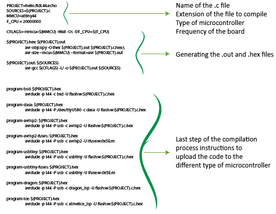
Basic structure the make file:
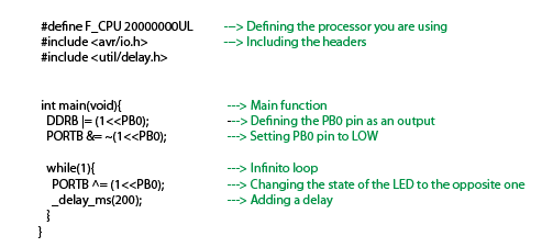
Basic structure of a .c program:
4. Input and Output ports:
As it was said before, the pins are gathered in groups of 8. Each of these groups is called Port. Every port has three types of registers:
For example, to set the 4th pin of the Port B as an output what you need to do is:
DDRB |= (1 << PB4);
To set it as an input:
DDRB &= ~(1 << PB4);Tu set the pin PA4 in HIGH:
PORTA |= (1 << PA4);
Tu set the pin PA4 in LOW:
PORTA &= ~(1 << PA4);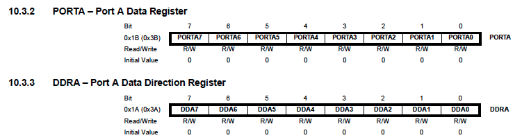
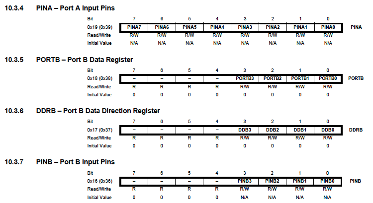
5. Interruptions:
An interruption is a process that will stop the current process of the microcontroller to do a differnt one. Once it finishes the interruption it will go back to where it was.
The main functions for the interruptions are:
- sei(); to enable the interruptions.
- cli(); disable the interruption.
6. Understanding the datasheet:
This week I have tried to understand the basics of the microcontroller datasheet and then in the next weeks I have deepen in some of these sections:
- Week 11: How to read the different ADC input signals
- Week 12: Working with the timers for switching on and off a vibration motor (and a LED).
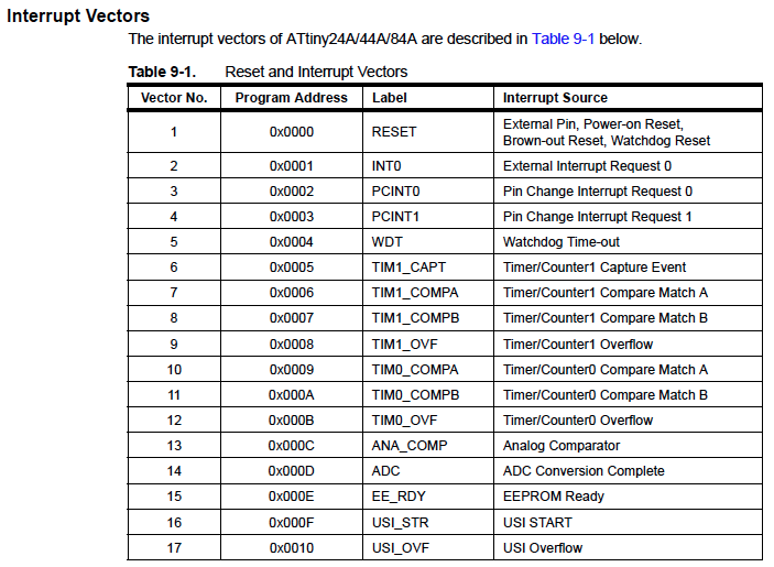
7. Software:
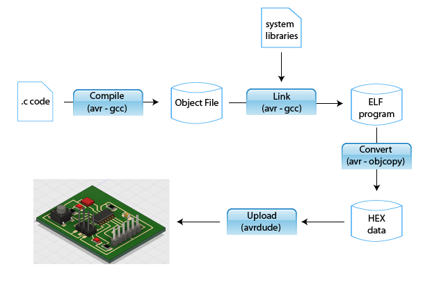
Compilling a program in .c:
We can find three type of languages when we are programming. The language that the microcontroller understand is " machine language", which is composed by 0s and 1s, binary, corresponding the first one to a low state and the second one to the high state. Then we have " assembly language", which is a low level language that uses a mnemonic to represent each low-level machine instruction. Then we have the high level language that enables a user to write programs in a language which resembles English words and familiar mathematical symbols. Each statement in a high level language is a micro instruction which is translated into several machine language instructions.
When working with a high level language you can work with IDEs that make the process easier or you can write the .c code directly. I first tried a few examples with Arduino and then I moved on to work with .c directly as is more efficient for the microcontroller. The "problem" of working with .c is that you need to have more knowledge about the micro architecture and it's registers.
8. Programming my board in Arduino:
The first programming that I did in my board, appart from the Hello World that I did on the 7th week, was done with Arduino's interface. I did three simple programs:
- The first one makes the light blink at a speed of 1000ms = 1s.
const int buttonPin = PA7;
const int redLedPin = PA3;
const int greenLedPin = PB2;


// the setup function runs once when you press reset or power the board
void setup() {
// initialize the red pin as an output.
    pinMode(redLedPin, OUTPUT);
}

// the loop function runs over and over again forever
void loop() {
  digitalWrite(redLedPin, HIGH);   // turn the redLED on (HIGH is the voltage level)
  delay(1000);                       // wait for a second
  digitalWrite(redLedPin, LOW);    // turn the LED off by making the voltage LOW
  delay(1000);                       // wait for a second
}
- The second one detects when the button is pressed and turns the Led on. For stablishing the button as an input I set it as PULL UP because I don't have a resistor in the board so I need to enable the internal one that the microcontroller has on each pin.
const int buttonPin = PA7;
const int redLedPin = PA3;
const int greenLedPin = PB2;
int buttonState = 0;

void setup() {
  Serial.begin(9600);
  // setting the LEDs to outputs and the button to output
  pinMode(redLedPin, OUTPUT);
  pinMode(greenLedPin, OUTPUT);
  pinMode(buttonPin, INPUT_PULLUP);


}

void loop() {
   buttonState = digitalRead(buttonPin);

    if (buttonState == LOW) {
      digitalWrite(redLedPin, HIGH);
      Serial.print('The red LED is on')
  } else {
    // turn LED off:
    digitalWrite(redLedPin, LOW);
    Serial.println("The red LED is off");
  }

}
-The third one is an extension of the previous program, but in this case when the button is pressed a message will be displayed in the serial monitor telling how many times it has been preseed. When the number of times that it has been pressed is even the LED will light up.
#include <SoftwareSerial.h>
const int rx = PA0;
const int tx = PA1;
const int buttonPin = PA7;
const int redLedPin = PA3;

int buttonState = 0;
int lastButtonState = 0;
int counter = 0;


SoftwareSerial mySerial(rx, tx);

void setup() {
  // put your setup code here, to run once:
    mySerial.begin(115200);
    pinMode(redLedPin, OUTPUT);
    pinMode(buttonPin, INPUT_PULLUP);

}

void loop() {
    // read the input pin:
  buttonState = digitalRead(buttonPin);
  if (buttonState !=lastButtonState){

    if (buttonState == LOW){
      counter++;
          mySerial.print("number of button pushes:  ");
          mySerial.println(counter);
          mySerial.println("");
      }

      delay(50);
    }

    lastButtonState = buttonState;

    if(counter % 2 == 0){
        digitalWrite(redLedPin, HIGH);
     }else{
        digitalWrite(redLedPin, LOW);
        }

  delay(400);

}
9. Programming in .c:
I first programmed a simple LED in .c to explain the process and then I did another one a bit more complex using timers and interruptions.
- First thing to do is to create the
makefile where the microcontroller that is going to be used is defined (picture below), and the rest of the make file structure that was explained before: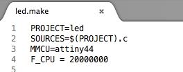
- Then we create the
.cfile, in this case my first one was calledled.c, as you can see in the previous make file. - Define the microcontroller speed that is used:
#define F_CPU 20000000L - Include the library headers:
#include <avr/io.h>

#include <util/delay.h> - Main function:
- The CLKPCE bit must be written to logic one to enable change of the CLKPS bits.
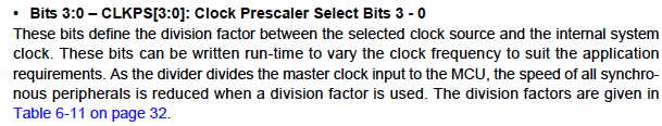
- Setting the clock division factors (CLKPS3, CLKPS2, CLKPS1) to 1. These bits define the division factor between the selected clock source and the internal system clock.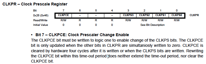
- Initialize the Led pin. We set it as LOW state and as an output.
PORTA &= ~(1 << PA3); - Creating a loop that will change the LED state every certain period of time.
- Once you have your .c file, you save in the same file where you have created the make file and you run it in the console in the same way that was done with the hello world program.
$sudo make -f led.make program-usbtiny
DDRA |= (1 << PA3);
#define F_CPU 20000000L    //Setting the speed of the microcontroller

#include <avr/io.h>
#include <util/delay.h>

//You can either work directly with the names of the ports or define them to make
//it easier and global

//Main function of the program

int main(void) {
   // Firs of all we have to set clock divider to /1
   CLKPR = (1 << CLKPCE); // Clock Prescaler Change Enable
   // Clock Division Factor set to 1
   CLKPR = (0 << CLKPS3) | (0 << CLKPS2) | (0 << CLKPS1) | (0 << CLKPS0);

   // initialize LED pin
   PORTA &= (~(1 << PA3));    //We put the state to LOW
   DDRA |= (1 << PA3);        //We set it as an output


   while (1) {   //main function, turning LED on and off

      PORTA |= (1 << PA3);
      _delay_ms(1000);
      PORTA &= (~(1 << PA3));
      _delay_ms(1000);
      }
   }
9. Sending an email when pushing the button:
I was looking for ideas of what to do with two leds and a button and my tutor told me that I could generate a script with python that has the instructions for sending an email.
The condition was that when the .py receives an 'M', an email is sent to the address that is specified in the script.
- I search for a tutorial that told me the protocols that I had to include in the Python script in order to send an email:
import time import serial import smtplib TO = '---' GMAIL_USER = '---' GMAIL_PASS = '---' print("I have the mail information") SUBJECT = 'Testing my email by button' TEXT = 'If you are receiving this it means that it works!' ser = serial.Serial('/dev/cu.usbserial-FTFMJ6MW', 115200) print("I have the serial info") def send_email(): print("Sending Email") smtpserver = smtplib.SMTP("smtp.gmail.com",587) smtpserver.ehlo() smtpserver.starttls() smtpserver.ehlo smtpserver.login(GMAIL_USER, GMAIL_PASS) header = 'To:' + TO + '\n' + 'From: ' + GMAIL_USER header = header + '\n' + 'Subject:' + SUBJECT + '\n' print header msg = header + '\n' + TEXT + ' \n\n' smtpserver.sendmail(GMAIL_USER, TO, msg) smtpserver.close() while True: print("I am inside the while") message = ser.readline() print("I read the message") print(message) if message[0] == 'M' : send_email() time.sleep(0.5) - I wrote a C code that sends a 'M' character when the button is pressed and a 'U' when is relased.
I firts define what the outputs and the inputs were going to be, and the functions that will be used. The input is the button and the output is a LED that will be on when the button is sending the M.
#include <avr/io.h>
#include <util/delay.h>

#define output(directions,pin) (directions |= pin) // set port direction for output
#define input(directions,pin) (directions &= (~pin)) // set port direction for input
#define set(port,pin) (port |= pin) // set port pin
#define clear(port,pin) (port &= (~pin)) // clear port pin
#define pin_test(pins,pin) (pins & pin) // test for port pin
#define bit_test(byte,bit) (byte & (1 << bit)) // test for bit set
#define bit_delay_time 8.5 // bit delay for 115200 with overhead
#define bit_delay() _delay_us(bit_delay_time) // RS232 bit delay
#define half_bit_delay() _delay_us(bit_delay_time/2) // RS232 half bit delay

#define input_port PORTA
#define input_direction DDRA
#define input_pin (1 << PA7)
#define input_pins PINA

#define serial_port PORTA
#define serial_direction DDRA
#define serial_pin_out (1 << PA1)

#define led_port PORTA
#define led_direction DDRA
#define led_pin (1 << PA3)

// Declaracion de funciones
void put_char(volatile unsigned char *port, unsigned char pin, char txchar);
Then the main function which inside the main while has two other whiles that what they are going to do is stay in the loop while no signal is triggered. Is another way of waiting without using delays. Then we have the calls to the put_char function, that will allow to send the M and the U to the serial monitor. The set and clear are just switching the LED on an off.
int main(void) {
   //
   // main
   //
   // set clock divider to /1
   //
   CLKPR = (1 << CLKPCE);
   CLKPR = (0 << CLKPS3) | (0 << CLKPS2) | (0 << CLKPS1) | (0 << CLKPS0);
   //
   // initialize pins
   //
   set(serial_port, serial_pin_out);
   output(serial_direction, serial_pin_out);
   set(input_port, input_pin); // turn on pull-up
   input(input_direction, input_pin);
   //
   // main loop
   //
       while (1) {
          //
          // wait for button down
          //
          while (0 != pin_test(input_pins,input_pin))
             ;
          put_char(&serial_port, serial_pin_out, 'M');
          put_char(&serial_port, serial_pin_out, 10);
          clear(led_port, led_pin); // PA7 LOW
          set(led_port, led_pin);


          while (0 == pin_test(input_pins,input_pin))
             ;
             put_char(&serial_port, serial_pin_out, 'U');
             put_char(&serial_port, serial_pin_out, 10);
             set(led_port, led_pin); // PA7 HIGH
             clear(led_port, led_pin);
    }
}
And finally, this is the put_char function that I am using, which was the one we were using in the Hello World programm the 7th week.
void put_char(volatile unsigned char *port, unsigned char pin, char txchar) { // // send character in txchar on port pin // assumes line driver (inverts bits) // // start bit // clear(*port,pin); bit_delay(); // // unrolled loop to write data bits // if bit_test(txchar,0) set(*port,pin); else clear(*port,pin); bit_delay(); if bit_test(txchar,1) set(*port,pin); else clear(*port,pin); bit_delay(); if bit_test(txchar,2) set(*port,pin); else clear(*port,pin); bit_delay(); if bit_test(txchar,3) set(*port,pin); else clear(*port,pin); bit_delay(); if bit_test(txchar,4) set(*port,pin); else clear(*port,pin); bit_delay(); if bit_test(txchar,5) set(*port,pin); else clear(*port,pin); bit_delay(); if bit_test(txchar,6) set(*port,pin); else clear(*port,pin); bit_delay(); if bit_test(txchar,7) set(*port,pin); else clear(*port,pin); bit_delay(); // // stop bit // set(*port,pin); bit_delay(); // // char delay // bit_delay(); } - So, once I had the code, I loaded it in my board
$sudo make -f program.make program-usbtiny. - I checked that the characters were being sent properly when pressing the button by opening a new monitor serial in Arduino.
And it was, so I continue to execute the python script on the console.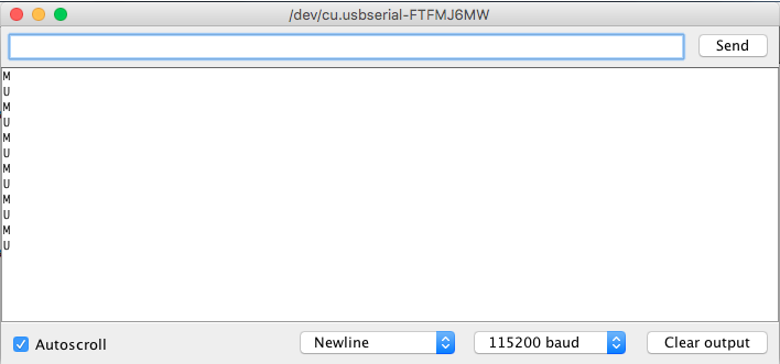
- I wrote
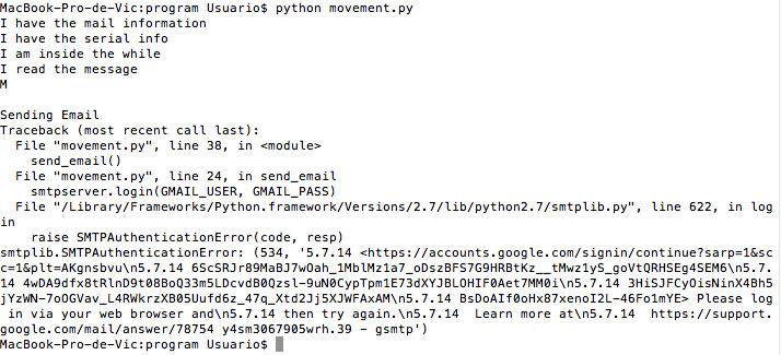
python movement.pyin the terminal and the program started to execute. As I described in the previous problem section, the first time it was stuck because it was waiting for the line break.
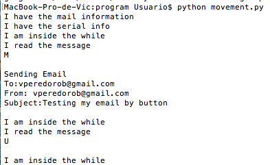
- I changed this acces option and finally my script was working!

PROBLEM!
= when I first wrote the .c code I didn't insert a line break put_char(&serial_port, serial_pin_out, 10); so the letters were displaying one after the other. As the python program was waiting for a line, it was stuck in the message = ser.readline() line. So I added the line break and I run it again.
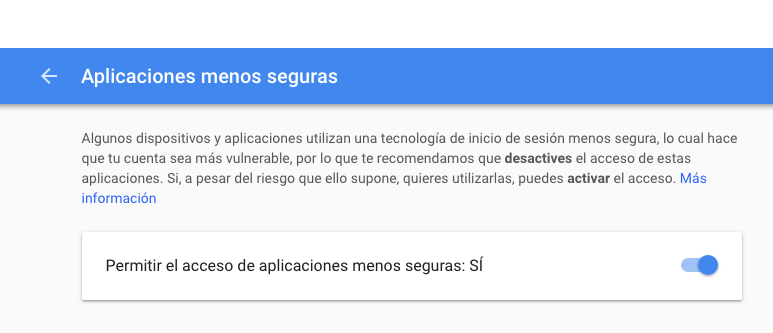
PROBLEM 2 :
Once the other problem was fixed I had another one. As I was trying to send an email through my gmail account, the security features of GMAIL were detecting this process as a danger. In order to fix it I had to allow 'Less secure apps' to acces my email.
10. What questions do you have? What would you like to learn more about?
Right now I didn't have time to get to know all the things that can be done with a microcontroller, I will learn about ADC reading in the inputs week, about timers in the output week, but I would like to understand better how to work with interruptions.
Group assignment:
Group assignment pageUsing another architecture, Raspberry Pi 3:
Basics of the Raspberry Pi:
A Raspberry Pi is "a credit card-sized computer". The Raspberry Pi is not as fast as a modern laptop but it is a complete Linux computer. It can provide all the expected abilities that implies at a low-power consumption level.
What is characteristic of the Raspberry Pi 3 as a board is the number of GPIO ports that it has. You can see in the image bellow how they are distributed:
Of the 40 pins, 26 are General purpose input/output (GPIO) pins and the others are power or ground pins. Click here to see the documentation.
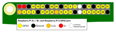 It's important knowing how to connect the I/O in order not to kill the board. You have to know if what you are connecting to the Pi uses a lot of power or not!
- When the pin is HIGH it outputs 3.3 volts (3v3)
- When the pin is LOW it is off.
For working with the pins you can either use the GPIO numbering or the physical numbering. The first way is how the computer sees the pins and the second one you refer to the pins is by simply counting across and down from pin 1 at the top left (nearest to the SD card). It is better to get used to know the GPIO numbering that you can find in this site.
Doing a tutorial for programming the Raspberry Pi:
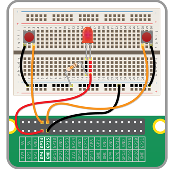
To learn how to use the Raspberry I followed this Tutorial. It guides you to programm a quick reaction game using python.
Hardware needed
- 1 x Breadboard
- 1 x LED
- 1 x 330 ohm Resistor
- 4 x Male-to-female jumper wires
- 2 x Male-to-male jumper wires
- 2 x Tactile push buttons
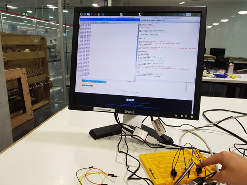
The circuit that I had to build was this cone:
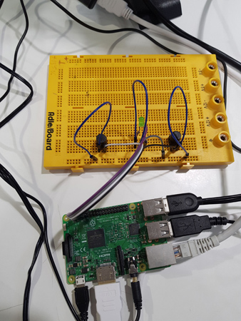
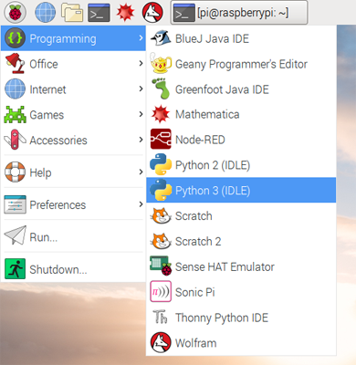
Once the circuit is build I start to program the board. For doing so I opened IDLE3 (as the tutorial recommended using this one), Python’s Integrated Development Environment, that can be used to write the code in the Raspberry. I created a new file called reaction.py.
The aim of this game is that the LED is switched on every a certain time, being this time random, and the two players have to click as fast as they can whenever the LED is turned on.
For using a LED the code that you need to write is quite simillar as when using Arduino or other IDE. You need to import it: from gpiozero import LED
Then you need to set in what pin is the LED connected. led = LED(17). And then in order to switch it on and off you need to write: led.on() and led.off(). There is also another function when warking with LEDs that is led.blink(a,b) which will make the LED blink, being a second on and b seconds off.
For the button, we initialize it in the same way: library from gpiozero import Button and we set the pin: button = Button(2)what we need to listen to the input is: button.wait_for_press()
A combination for LED and button can be:
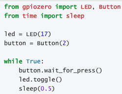
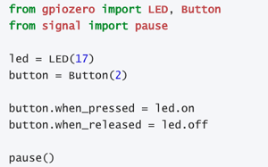
In this case, for the I first had to import the different libraries.
- LED and button pins.
-Time: to add a delay in the program using sleep.
-Random: to be able to generate a random time.
-Sys: for when I wanted the game to end every round.
Then I asked for the players names and I set the inputs and outputs that will be used, the LED and the two buttons.
I created a function that detects which of the players pressed before the button and that saves the score that they both have.
from gpiozero import LED, Button
from time import sleep
from random import uniform
from sys import exit
left_name = input('left player name is ')
right_name = input('right player name is ')
score_left = 0
score_right = 0
led = LED(4) #Setting the pin 4 as the LED output
right_button = Button(15) # Setting the buttons as an input
left_button = Button(14)
led.on() #Turning it on
sleep(uniform(5, 10)) #In order to play tha game we set the sleeping time to be random
led.off() # turning the LED off
def pressed(button):
global score_left
global score_right
if button.pin.number == 14:
print(left_name + ' won the game')
score_left +=1
print('Current score:' + repr(score_left))
else:
print(right_name+ ' won the game')
score_right +=1
print('Current score:' + repr(score_right))
#exit() If you want the game to only be played once you call exit()
while True:
#print("Inside the while")
right_button.when_pressed = pressed
left_button.when_pressed = pressed
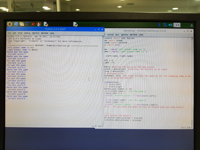
time.sleep(1)
Once the code was ready I clicked in the Run tab, or you can also press F5 in the keyboard to run the program. A new python window opened, the one you can see on the left of the picture displaying the messages that we have set when the different actions take place.