Week 14
Embedded Networking and Communications
Group assignment
Individual assignment
Learning outcomes:
- Demonstrate workflows used in network design and construction.
- Implement and interpret networking protocols.
Have you:
- Described your process using words/images/screenshots.
- Explained the programming process/es you used.
- Outlined problems and how you fixed them.
- Included original design files and code.
Individual assignment:
1. Bluetooth device:
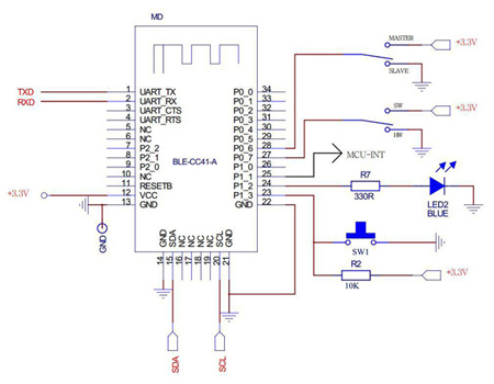
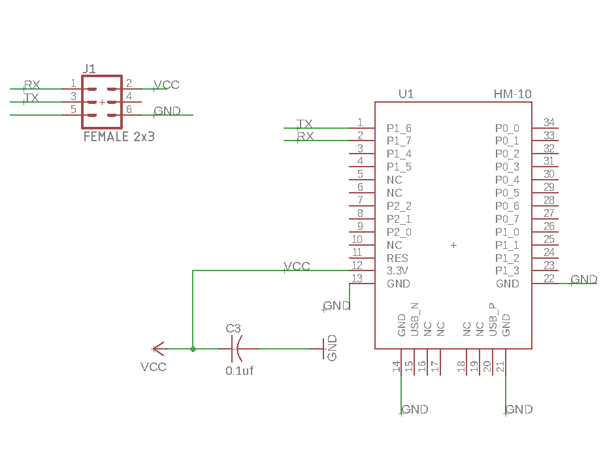
For communicating my board with my phone I will use the HM-10 bluetooth. It's a small 3.3v SMD Bluetooth 4.0 BLE module based on the TI CC2540 or CC2541 Bluetooth SOC (System On Chip).
Basic characteristics of the device:
- Voltage: from +2.5v to +3.3v
- Minimum current: 50mA.
- Power consumption: around 9mA when is inactive and aroun 50-200uA when asleep.
- Bluetooth version 4.0 BLE
- Serial communication at 9600.
- Default PIN is 000000
- Default name is HMSoft
The structure of this HM-10 is described in this picture:
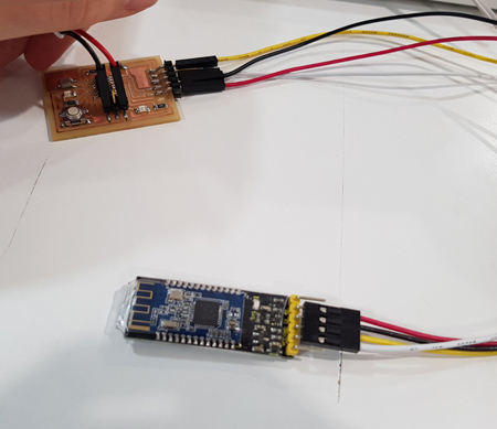
I was using the Keyestudio that can be connected to the FTDI directly in this way: 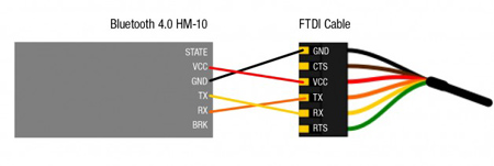
A. BLE scanner:
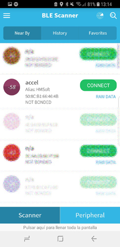
I downloaded BLE scanner on my phone to be able to communicate with the Bluetooth. I connected the FTDI to the board and I search for in on the app.
Once the Bluetooth board is connected I opened Arduino's Serial monitor and I typed AT+NAME? and I got OK+NAME:HMSoft so it was connected properly.
To be able to communicate I need the MAC address so for obtaining it I wrote AT+ADDR?: ADDR:508CB166464B.
Characteristics:
- AT+NAME = NAME:HMSoft. I changed it to: accel by writing
AT+NAMEaccel. When you write that you receive OK+Set:accel. Then you need to restart - AT+ADDR? = ADDR:508CB166464B.
- AT+BAUD? = Get:0. This means that is set to 9600.
For more AT commands : Link
B. Serial communication
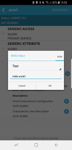
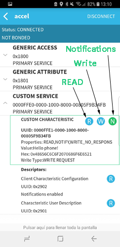
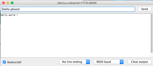
I tried to communicate from the BLED app of my phone to the serial monitor that is connected to the Bluetooth. I opened the App and I search my Bluetooth, as I have changed the default name, I looked for accel. I clicked on connect and then I clicked on the W button to write a message that will appear in the terminal.
I also tested the other way communication, I sent a message from the terminal Hello phone to the App. In order to see the message have to enable the notifications.
C. Serial communication: button + Bluetooth
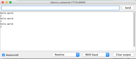
I also tried the communication between the board that I re-designed in the Week 07 and the Bluetooth module. For doing so I uploaded a .c program to the board where a 'Hellow world is sent whenever the button is pressed and a 2 when is released. The code that I used is written bellow.
//
//
//
// node_button
//
// attiny44 20 MHz
//    9600 baud FTDI interface
//
// Neil Gershenfeld
// 10/31/10
//
// Epifanio Lorenzo 01/05/17
// (c) Fab Lab Madrid CEU 2017
//
// This work may be reproduced, modified, distributed,
// performed, and displayed for any purpose. Copyright is
// retained and must be preserved. The work is provided
// as is; no warranty is provided, and users accept all
// liability.
//
// Modified program to send char when button pressed
// Victoria Peredo
//

#include <avr/io.h>
#include <util/delay.h>

#define output(directions,pin) (directions |= pin) // set port direction for output
#define input(directions,pin) (directions &= (~pin)) // set port direction for input
#define set(port,pin) (port |= pin) // set port pin
#define clear(port,pin) (port &= (~pin)) // clear port pin
#define pin_test(pins,pin) (pins & pin) // test for port pin
#define bit_test(byte,bit) (byte & (1 << bit)) // test for bit set
#define bit_delay_time 102 // bit delay for 9600 with overhead
#define bit_delay() _delay_us(bit_delay_time) // RS232 bit delay
#define half_bit_delay() _delay_us(bit_delay_time/2) // RS232 half bit delay

#define input_port PORTA
#define input_direction DDRA
#define input_pin (1 << PA7)
#define input_pins PINA

#define serial_port PORTA
#define serial_direction DDRA
#define serial_pins PINA
#define serial_pin_out (1 << PA1)


void put_char(volatile unsigned char *port, unsigned char pin, char txchar);


int main(void) {
  static char chr;
  //
  // main
  //
  // set clock divider to /1
  //
  CLKPR = (1 << CLKPCE);
  CLKPR = (0 << CLKPS3) | (0 << CLKPS2) | (0 << CLKPS1) | (0 << CLKPS0);
  //
  // initialize pins
  //
  set(serial_port, serial_pin_out);
  output(serial_direction, serial_pin_out);
  set(input_port, input_pin); // turn on pull-up
  input(input_direction, input_pin);
  //
  // main loop
  //
  while (1) {
    //
    // wait for button down
    //
    while (0 != pin_test(input_pins, input_pin))
      ;
    //
    put_char(&serial_port, serial_pin_out, 'h');
    put_char(&serial_port, serial_pin_out, 'e');
    put_char(&serial_port, serial_pin_out, 'l');
    put_char(&serial_port, serial_pin_out, 'l');
    put_char(&serial_port, serial_pin_out, 'o');
    put_char(&serial_port, serial_pin_out, ' ');
    put_char(&serial_port, serial_pin_out, 'w');
    put_char(&serial_port, serial_pin_out, 'o');
    put_char(&serial_port, serial_pin_out, 'r');
    put_char(&serial_port, serial_pin_out, 'l');
    put_char(&serial_port, serial_pin_out, 'd');
    //put_char(&serial_port, serial_pin_out, 10); // new line

    //
    // wait for button up
    //
    while (0 == pin_test(input_pins, input_pin))
      ;
    put_char(&serial_port, serial_pin_out, '2');
    put_char(&serial_port, serial_pin_out, 10); // new line

  }
}


void put_char(volatile unsigned char *port, unsigned char pin, char txchar) {
  //
  // send character in txchar on port pin
  //    assumes line driver (inverts bits)
  //
  // start bit
  //
  clear(*port, pin);
  bit_delay();
  //
  // unrolled loop to write data bits
  //
  if bit_test(txchar, 0)
    set(*port, pin);
  else
    clear(*port, pin);
  bit_delay();
  if bit_test(txchar, 1)
    set(*port, pin);
  else
    clear(*port, pin);
  bit_delay();
  if bit_test(txchar, 2)
    set(*port, pin);
  else
    clear(*port, pin);
  bit_delay();
  if bit_test(txchar, 3)
    set(*port, pin);
  else
    clear(*port, pin);
  bit_delay();
  if bit_test(txchar, 4)
    set(*port, pin);
  else
    clear(*port, pin);
  bit_delay();
  if bit_test(txchar, 5)
    set(*port, pin);
  else
    clear(*port, pin);
  bit_delay();
  if bit_test(txchar, 6)
    set(*port, pin);
  else
    clear(*port, pin);
  bit_delay();
  if bit_test(txchar, 7)
    set(*port, pin);
  else
    clear(*port, pin);
  bit_delay();
  //
  // stop bit
  //
  set(*port, pin);
  bit_delay();
  //
  // char delay
  //
  bit_delay();
}
I opened a terminal in order to check that the board was working properly and was displaying a 'Hello world' when the button was pressed and a 2 when it was not.
I then connected the Bluetooth device pins (VCC, GND, TX and RX) to the FTDI pins that I had in the board, and I connected the VCC and GND from the FTDI cable to the SPI :
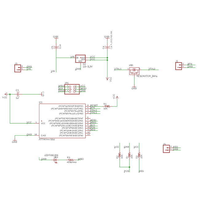
2. Creating a board for the conductive thread
The Input week I tried the different sensors that I am going to include in my final project. One of them is the condudctive fabric that I will include in the t-shirt in order to measure how the muscles are stretching when slumping. This week I will do the final board for this purpose. This board will include:
- Blueooth to communicate with the phone App
- Microcontroller: Attiny 44
- Led and a button for debugging purposes
- Resonator
- Regulator
- Wheatstone bridge where the two threads of my sensor will be soldered.
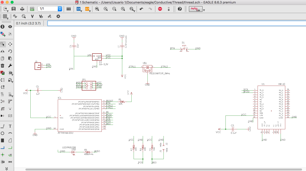
As the board that I created for the Output week also included the regulator, resonator, microcontroller and bluetooth I created a Design block in that schematic and I opened in my new board design.
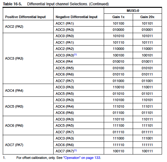
I needed to check on the ATTiny 44 datasheet which pins I could use to read my signal:
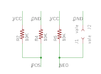
The way that I drawed in the schematic the Whatstone bridge was this one:
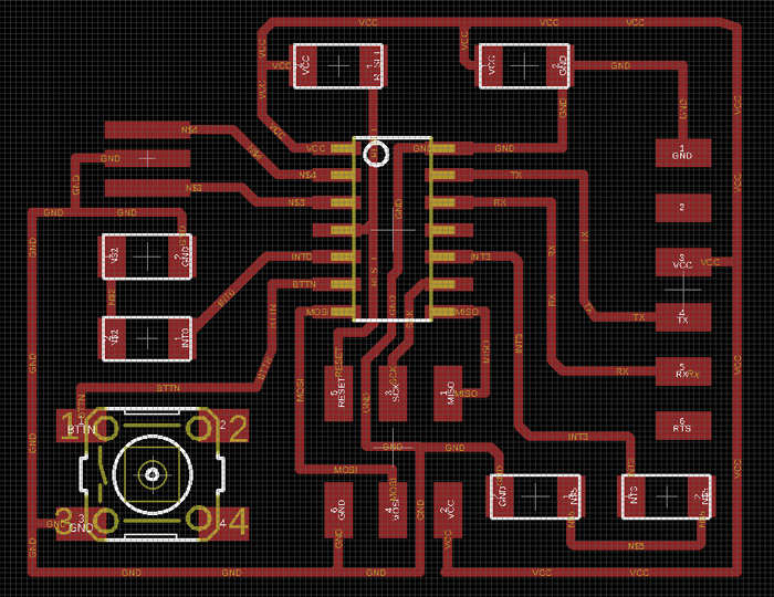
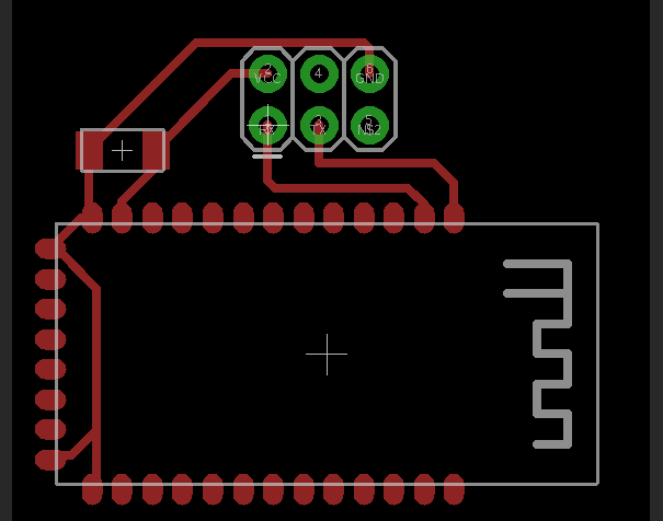
At first I included the Bluetooth in the schematic but when I started to do the board placement I decided to do two separate boards that will be placed one on top of the other.
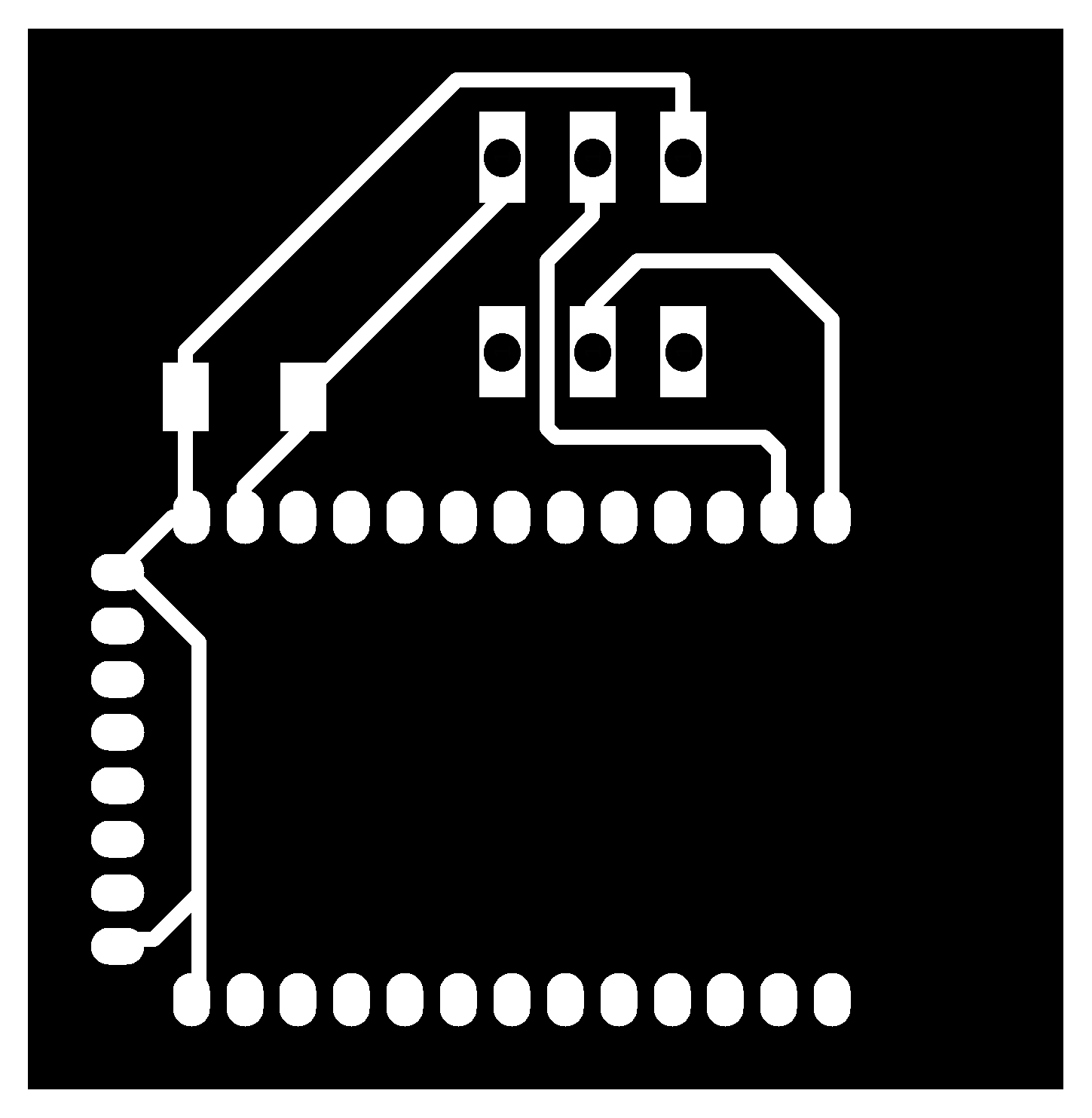
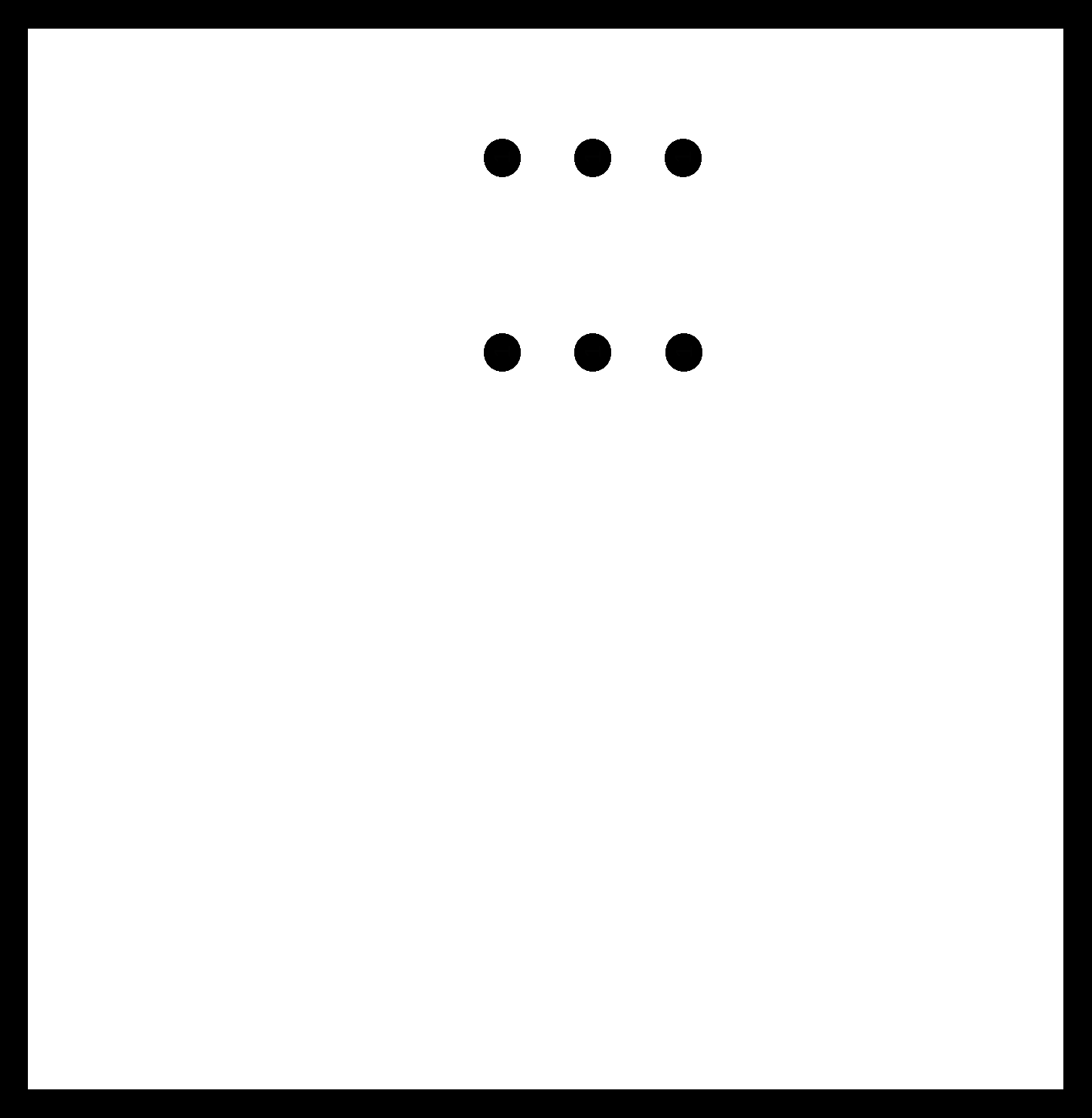
The final board will be divided in two boards that will be connected one to the other through the SPI connector.
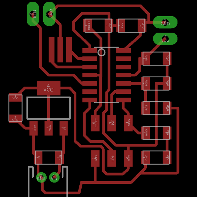
The bluetooth board will have a 3x2 connector that will be joined to the SPI header for the connection with the corresponding pins. Like this the size of the board will be reduced.
3. Milling and soldering the components:
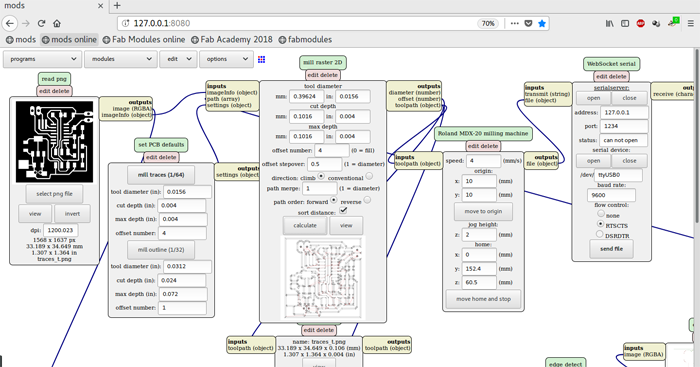
Once I had the two boards designed I exported the images as .png, doing the same process as the one I've been doing in the different weeks. Link to page explaining process. Adding 1.6mm on the sides and in this case I added two more holes on the thread board that will enable be to fix them to their corresponding box.
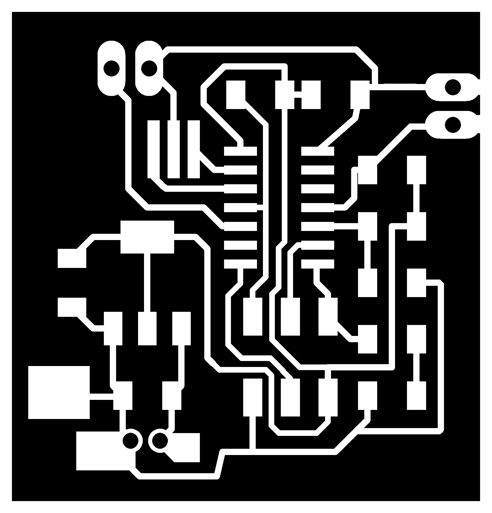
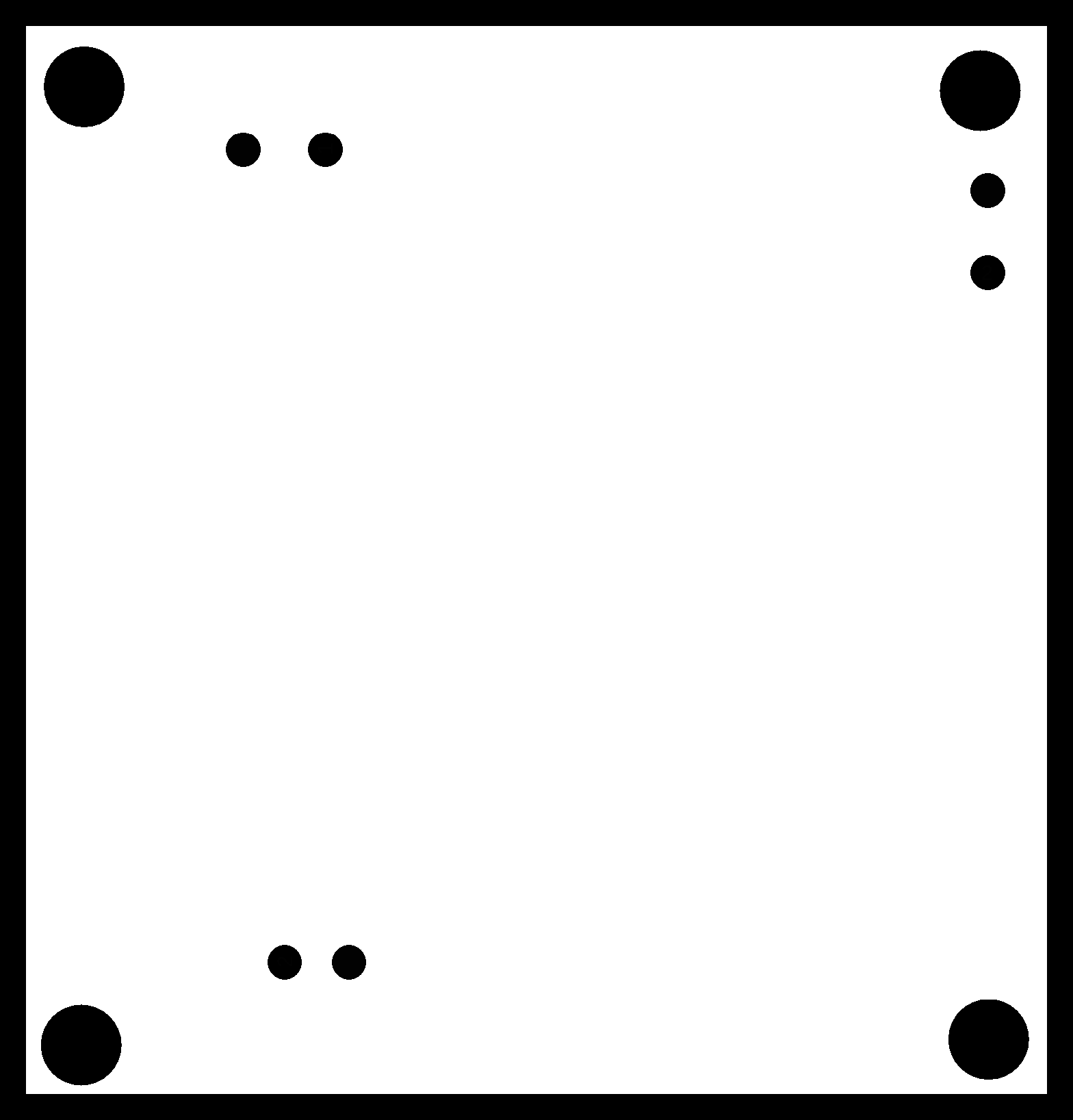
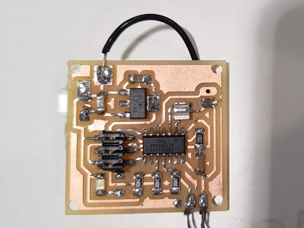
I used mods and the Modella to mill the boards, and then I solder the different components.
Final resulto of the board connected to the conductive thread on the bottom part.
4. Receiving data from thread board
For this week's assigment I wanted to stablish the connection between my board's bluetooth and my phone by creating an app with App inventor. First of all I ran a code on the thread board that will light up the LED whenever the board receives a 1 and will turn it off when receiving a 0.
Thread code:
#include <SoftwareSerial.h>

const int rx = PA4;
const int tx = PA6;
const int led = PA5;
//const int button = PA7;

SoftwareSerial mySerial(rx, tx);


void setup() {
  pinMode(led, OUTPUT);
  //pinMode(button, INPUT_PULLUP);
  mySerial.begin(9600);
}
void loop() {

  if (mySerial.available() > 0) {
    char ledState = mySerial.read();
    if (ledState == '1') {
      digitalWrite(led, HIGH);
      mySerial.println("ON");
    }
    else if (ledState == '0') {
      digitalWrite(led, LOW);
      mySerial.println("OFF");
    }
  }
//  int buttonState = digitalRead(button);
//  if ( buttonState == LOW) {
//    mySerial.println("Button is pressed");
//    delay(500);
}
Then I used the Ble scanner to test it sending a 1 and 0 to see if the board was receiving it. For now the bluetooth board is not directly connected to the board as I won't be able to program it if I do so. Once the I have the definitive program I will solder the bluetooth board.
In the previous video you can see that the communication was working, being able to switch it on and off with the ble scanner.
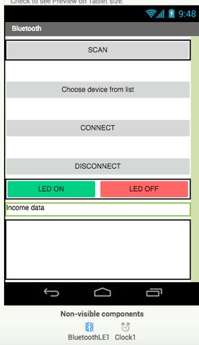
App Inventor 2
So then I created a new project on App inventor. I downloaded an extension that allowed me to work with Ble scanner. I created the following buttons:
- Scan button: to start the bluetoot scanning
- List button to choose to which device you want to make the coonection.
- Disconect
- Turn on and off the LED
The corresponding design blocks for this app are these ones. The process to create an app with App inventor is to display the different elements on the Designer and then you go to the Blocks section and you choose what actions you want to perform. In this example I'm writing a 0 and a 1 whenver the button is clicked.
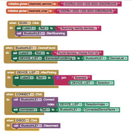
In the next video you can see how I connect to the app and how is the app working.
Group assignment: Group assignment page
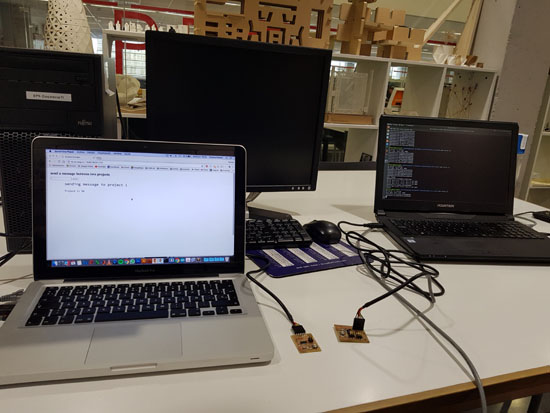
For this week's group assignment we have done a program using node, socket.io, express and serial that allows us to communicate two boards from two different computers.
We had two boards connected to each of the computers and by connecting to the server from the computers we were able to light the LED of boths boards.
The .c program that we loaded into the boards was a program that whenever the boar receives a number specific to it, it will light up twice and if is not it will only light up once. I loaded to my board a program that is reading through the serial and whenever it gets a 1 it will light up twice and send a message and if it reads any other nomber it will only do it once. :
#include <SoftwareSerial.h>

SoftwareSerial mySerial(0, 1); // RX, TX

const int id = '1';
const int ids = 1;
const int ledPin = PA3; //PA7
int ledState;


void setup() {
pinMode(ledPin, OUTPUT);
mySerial.begin(9600);
}

void loop() {
  if (mySerial.available()>0){
    ledState = mySerial.read();
    if (ledState == id){
      digitalWrite(ledPin,HIGH);
      delay(500);
      digitalWrite(ledPin,LOW);
      delay(500);
      digitalWrite(ledPin,HIGH);
      delay(500);
      digitalWrite(ledPin,LOW);
      delay(500);
      mySerial.println(ids);
  }
  else{
      digitalWrite(ledPin,HIGH);
      delay(500);
      digitalWrite(ledPin,LOW);
  }

  }
  delay(10);

}
The other board had the same code changing the id=1 for id = 2.
Then in the server.js we are creating a local server that will make the connection between the board and the web, defining from which port we were going to read from. We also set the file where the .html, the libraries and the sketch.js are installed, in this case the public one.
var express = require('express');
var app = express();
var server = app.listen(1234);
app.use(express.static('public'));
console.log("My server is running");

var socket = require('socket.io');
var io = socket(server);
io.sockets.on('connection', newConnection);
function newConnection(socket){
		console.log('newConnection:' + socket.id);
	socket.on('net', netMsg);

	function netMsg(data){
      socket.broadcast.emit('net', data);
			myPort.write(data);
   	}
	}

var SerialPort = require('serialport');
var myPort = new SerialPort("/dev/cu.usbserial-FTF0DTB9", {
	// velocidad
	baudRate: 9600,
	options: false,
	// como se leen los datos, se leen como texto hasta \n que es salto de linea
	parser: SerialPort.parsers.readline("\n")
});
// la libreria serialport se base en eventos
// estos son los principales
myPort.on('open', showPortOpen);
myPort.on('data', sendSerialData);
myPort.on('close', showPortClose);
myPort.on('error', showError);

function showPortOpen() {
   console.log('port open. Data rate: ' + myPort.options.baudRate);
}

function sendSerialData(data) {
   	io.emit('net', data);
  }

function showPortClose() {
   console.log('port closed.');
}

function showError(error) {
   console.log('Serial port error: ' + error);
}
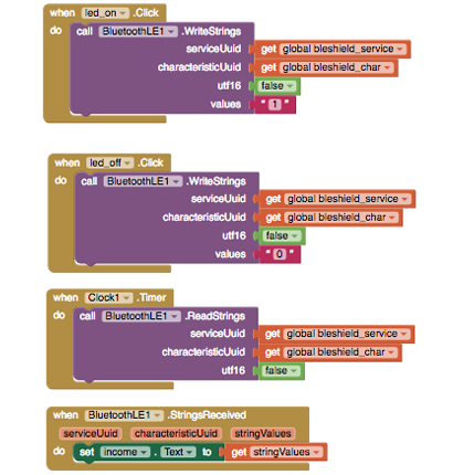
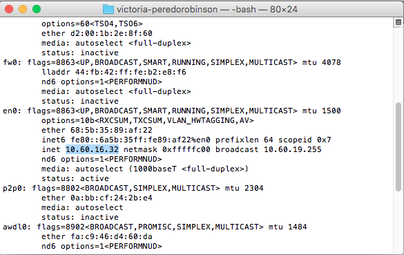
Then created the sketchjs were we deffined the sockets that we were using. My instructor was using one starting from 10.60.16 so I checked which one was mine by writing ifconfig in my console. We also defined what will be displayed on the screen. We will display a message saying which board is interacting.
sketch.js:
var socket, socket2;
 var input, button, greeting;
 //var img;

function setup() {
  createCanvas(1024, 762);
  background(255);
  textFont("Source Code Pro");
  socket = io.connect('http://10.60.16.186:1234');//mountain
  socket2 = io.connect('http://10.60.16.32:1234');
  socket.on('net', newDrawing);
  socket2.on('net', newDrawing);
  input = createInput();
  input.position(20, 65);

  button = createButton('enviar');
  button.position(input.x + input.width, 65);
  button.mousePressed(greet);

  greeting = createElement('h2', 'send a message between two projects');
  greeting.position(20, 5);

  //textAlign(CENTER);
  textSize(50);


}

function newDrawing(data) {

  if (data == 1){

    textSize(16);
    text("Project 1: OK", 80, 135);

console.log('enviado' + data);
  }
  else if (data==2){
    textSize(16);
    text("Project 2: OK", 80, 135);
      }


}

function greet() {
  var name = input.value();
  console.log('enviar' + name);
  socket.emit('net', name);
  socket2.emit('net', name);
  textFont("Source Code Pro");
  noStroke();
  rect(70, 110, 150, 40);
 noStroke();
  rect(60, 60, 500, 40);
  if (name==1){
    textSize(24);
    text("sending message to project 1", 80, 90);
     }
  else if (name==2){
    textSize(24);
    text("sending message to project 2", 80, 90);
      }
}

function draw() {

}
Once we had all the files ready we run the node. I had to change the version as I was using the 9th one and I needed 6th one. I did that by typing nvm use 6.14.1. Then we run the server by writing node server.js. We opened a window with the direction that we have stablished and we tried it sending 1 or 2.
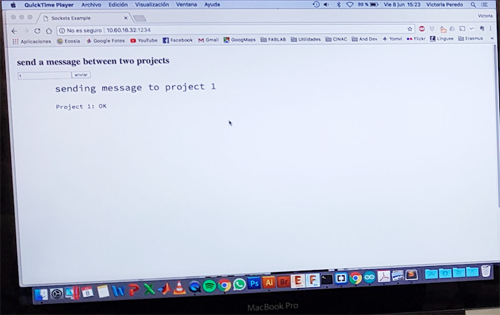
Here you can see our program in action! Whenever we write a one that board lights twice and sends an ok message back and when we write a 2 that one lights twice and sends an ok.