

My journey began by attending the Interior Design course at the Milan Polytechnic, concluded with a thesis on the study of the proxemics applied to the design of the interior spaces of a reception center for political refugees. During my studies I started working at Ragone Falegnameria (www.ragone.eu) from February 2011 to June 2017. Being a family-run business, I had the opportunity to take care of most of the activities right from the start. At first my main task, besides the ad hoc design of custom furnishing elements, was the realization of photorealistic renderings with Cinema4D for the brochures, designing both the furnishings (cabinets, kitchens and living) and the spaces, editing them at a later time in Photoshop. During these first three years I began to approach the craft, beginning to "steal" the trade. Starting from the most basic tools up, after six years, to big machines like the 5-axis CNC.
After 6 years I received the offer from Mastro Geppetto (www.mastrogeppettoarredamenti.it), a carpentry shop that deals with turnkey renovations. I was contacted because he needed a figure that would replace the designer next to the board, and eventually take over the company. To date, I am training as a carpenter and editor to get into the company's dynamics and to understand the design and management process of the various orders. After acquiring the right technical knowledge, I began to devote myself to personal projects outside the workplace that included a part of craftsmanship and a design. Among these there are skateboards of which I chose the wood and glued the various layers by hand, given the shape with software for 5-axis numerical control and finishing. My goal is to keep alive the two souls of my job, the design and the craft.

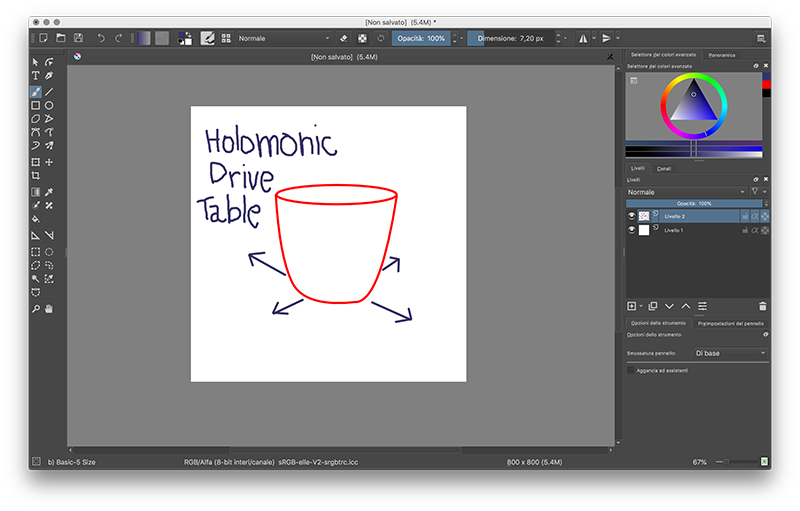
In planning the program for the realization of my omnidir table, I planned to do the necessary and difficult things first, such as the programming of the omnidirectional wheels, and to cascade all the things gradually simpler, such as cnc milling.
I would have liked very much to control the movements of the table through a multitouch remote control, but I found a lot of difficulties in writing the sketch for moving the wheels, so I gave priority to the board and its programming.
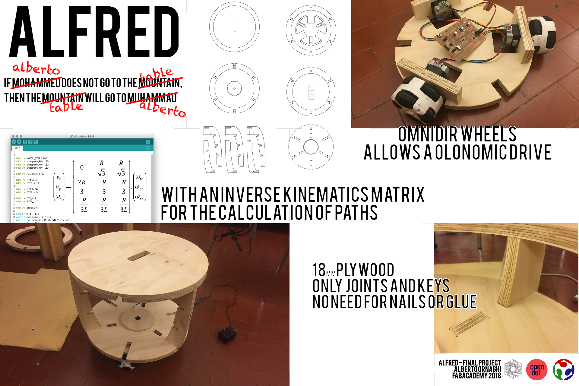
My goal for this final project is to create a starting point that could be applicable for different purposes. A machine composed of three omnidirectional wheels that allow the holonomic movement, to which you could connect different "shield" to turn it into anything that would need to move through a remote control.
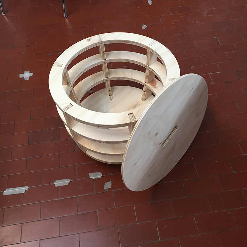
THE BODY
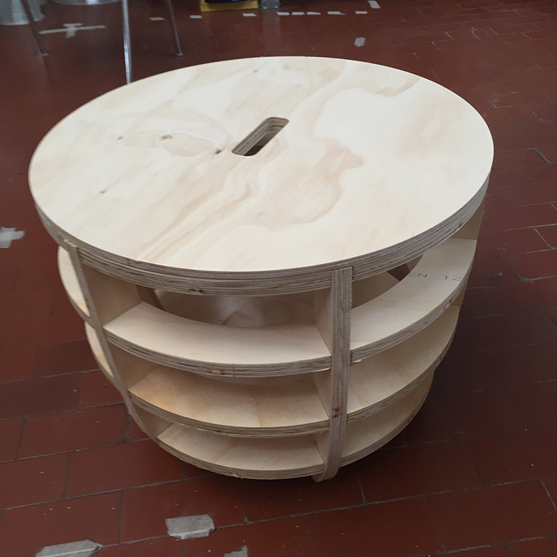
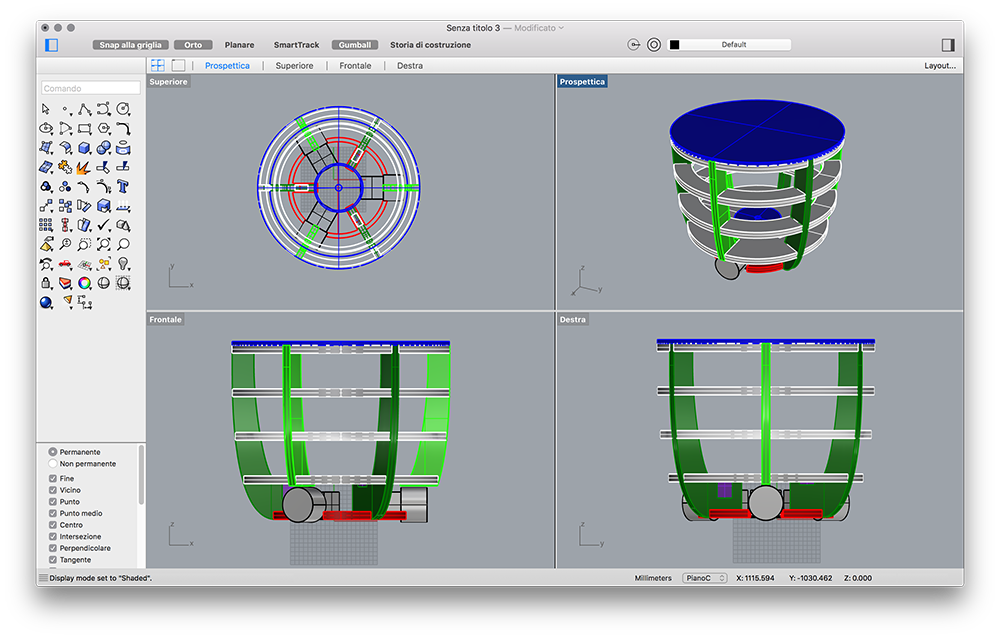
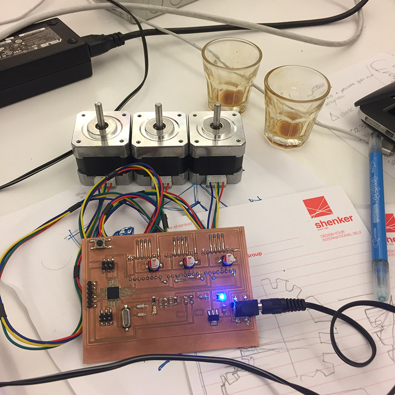
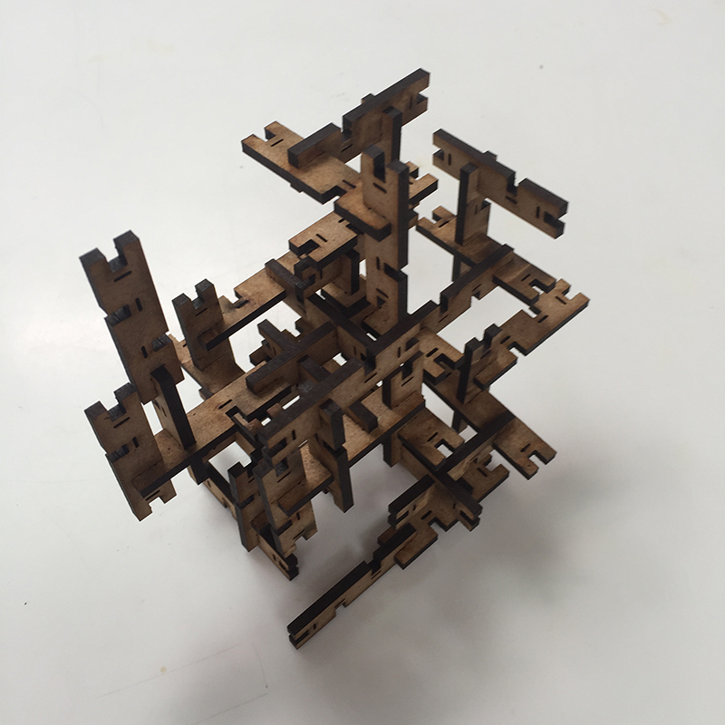
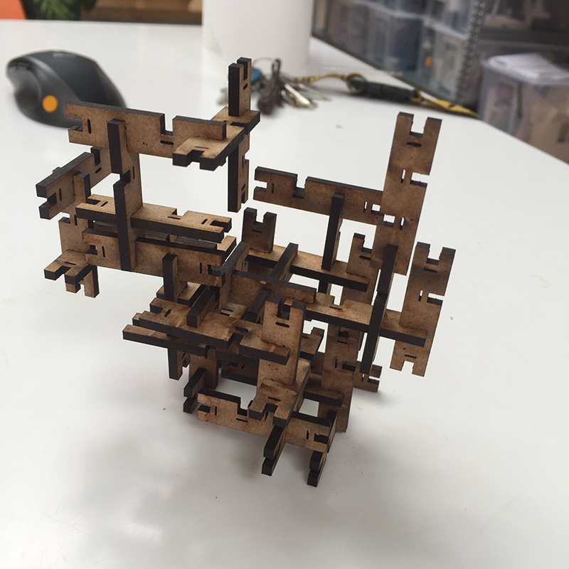
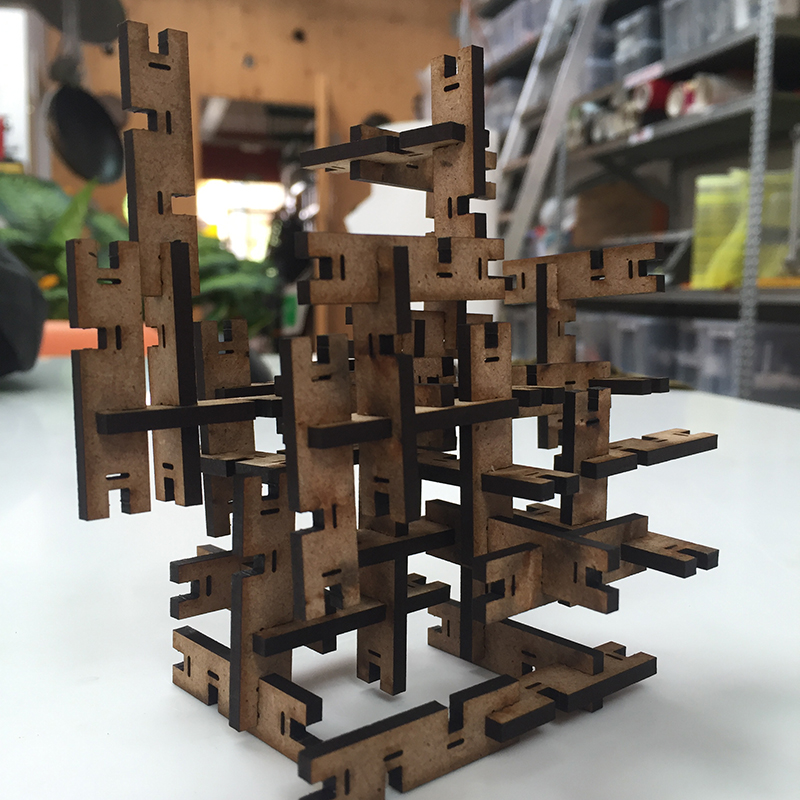
For the realization I wanted to upgrade the table realized in the numerical control cutting exercise. I made a small table with a circular section of 18mm plywood, composed of five horizontal circular parts held together by 6 vertical elements. All the pieces are joined together.
The design and all the segments are designed to be covered with thin sheets of wood or fabric.
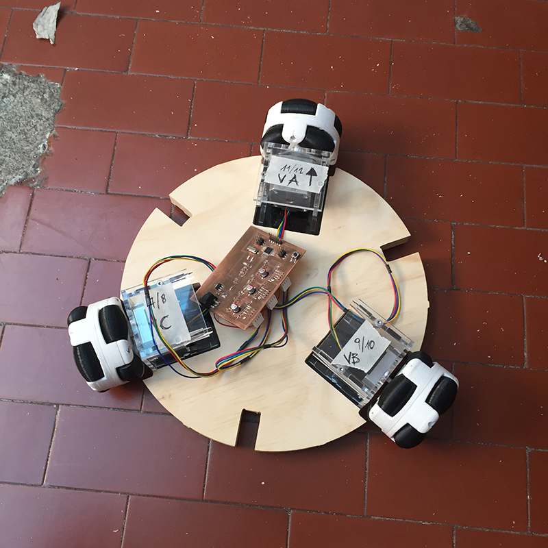
The two lower horizontal sections act as accommodation for the board, engines and wheels.
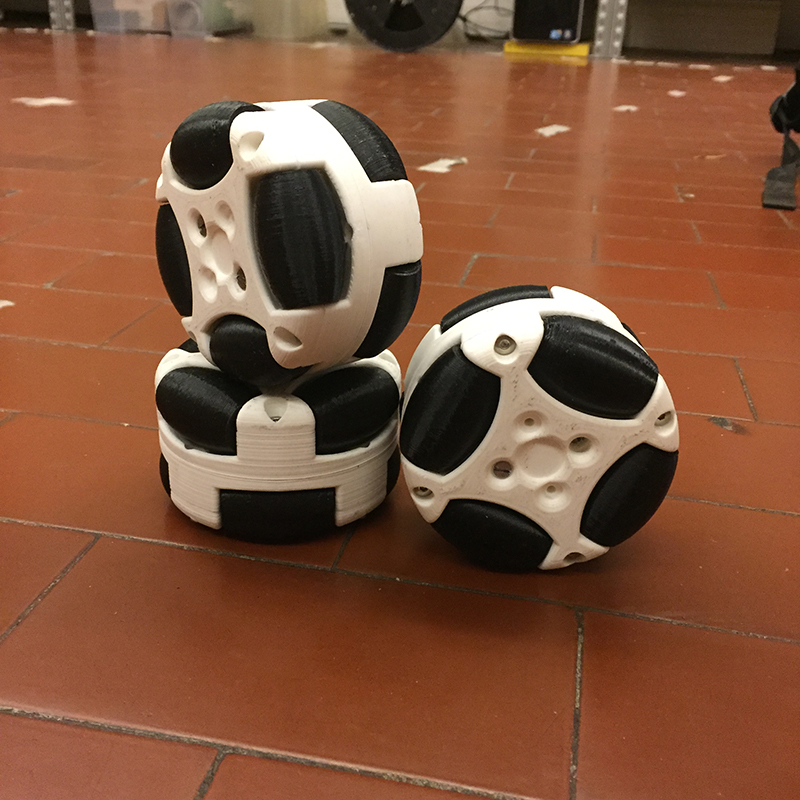
THE WHEELS
The wheels are the same used for the machine design exercise.
They are three omnidirectional wheels with a diameter of 58mm positioned to form an equilateral triangle.
Unlike the basket of machine design, I decided to use 3 wheels instead of 4 because in this way with any differences in height all the wheels touch the floor, returning a more faithful movement.
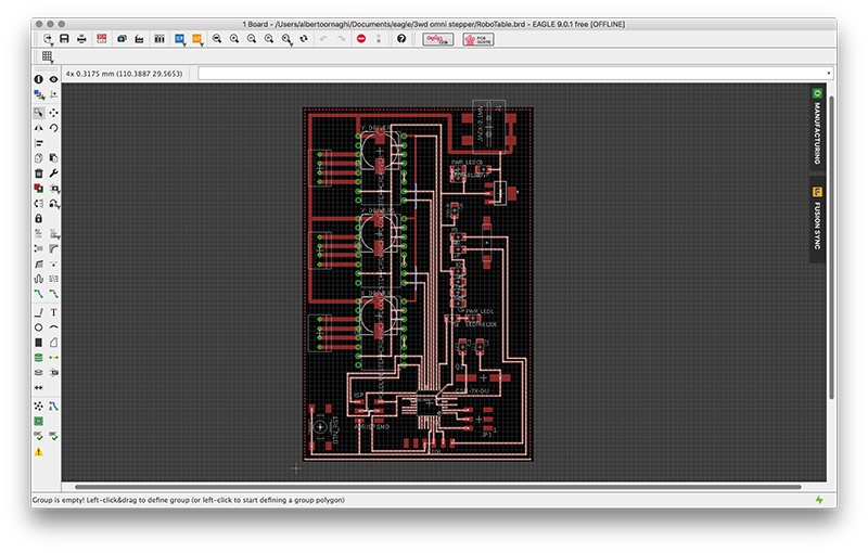
THE BOARD
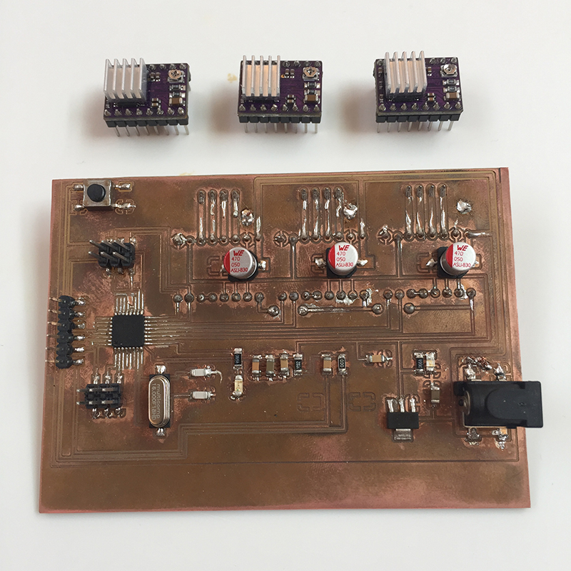
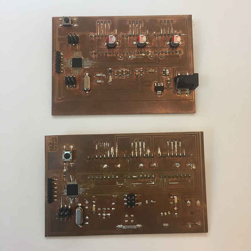
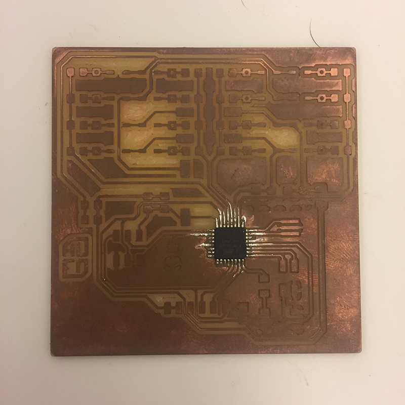
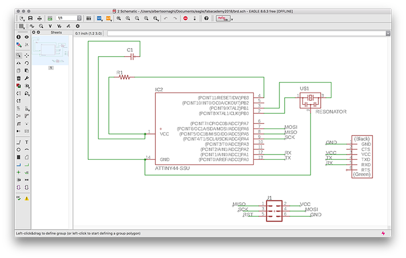
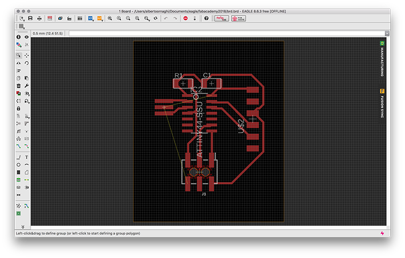
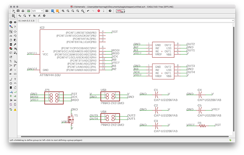
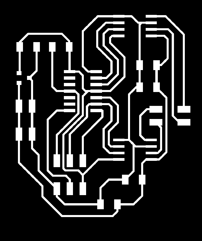
For the design of the board I started from the schematic fact for the week of machine design. I cleaned all the traces and redid all the connections to fit the housing of three drivers for stepper motors.
Although it is something that should not be done, to avoid making further bridges between the various connections, I used the MISO and the MOSI in common with the two DIR and STEP pins of the driver of an engine, so when the program is loaded one of the wheels starts to turn.
One thing that I found very comfortable is the mass plan that has simplified the drafting of the tracks, but on the other hand requires a little more attention when welding all the components to ground because it is more difficult to heat the copper to make it stick well the pond.
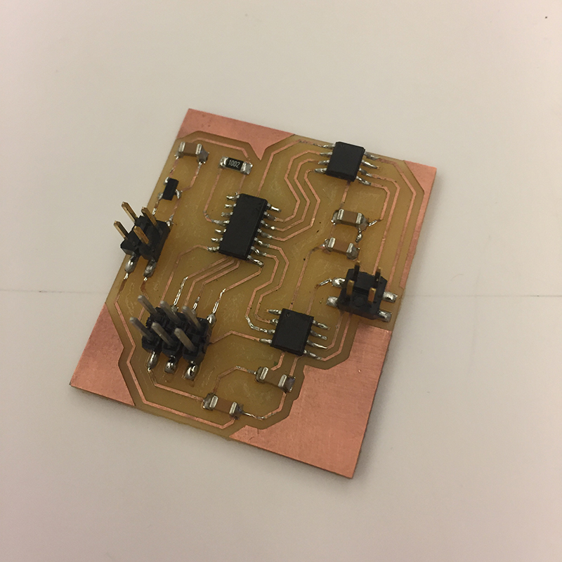
On the back of the board the three POLOLU DRV8825 drivers and the connectors for stepper motors have been installed.
The drivers have been fixed to the board with pineaders one centimeter high, in this way they have better ventilation, thus avoiding overheating thanks to the heat sinks glued to the microcontroller.
The components used are:
- n° 1 ATMEGA 328
- n° 3 STEPPER DRIVER POLOLU DVR8825
- n° 1 16 MHz CRYSTAL
- n° 2 CAPACITOR 22pF
- n° 2 CAPACITOR 4.7uF
- n° 1 CAPACITOR 10uF
- n° 2 CAPACITOR 1uF
- n° 1 CAPACITOR 100nF
- n° 3 POLARIZED CAPACITOR 4.7uF
- n° 2 RESISTOR 499Ω
- n° 1 RESISTOR 10KΩ
- n° 1 RESISTOR 0Ω
- n° 1 REGUALTOR 5V
- n° 1 BLUE LED
- n° 1 RED LED
- n° 1 SWITCH
- n° 1 JACK 2.1mm
- n° 1 2x3 SMD
- n° 1 2x3 ISP SMD
- n° 1 1x6 FTDI SMD
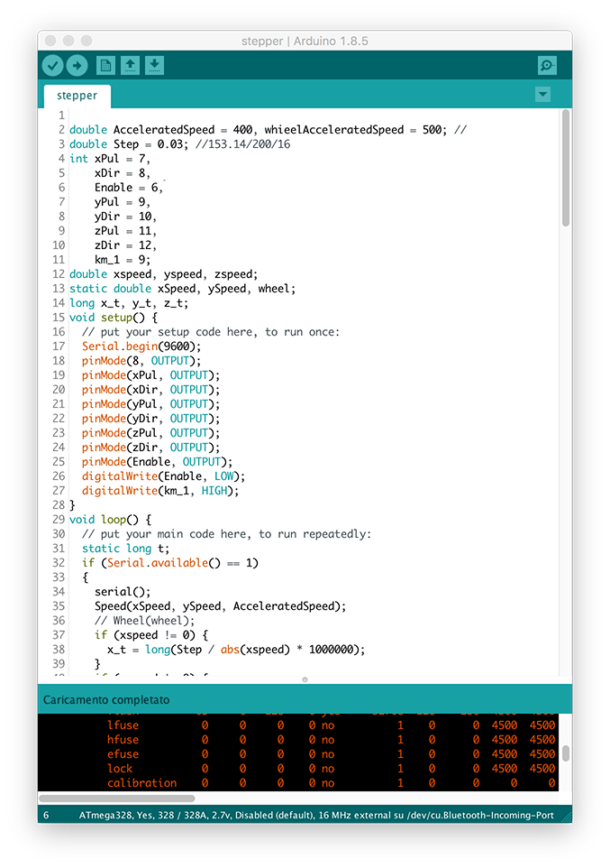
THE SKETCH
The writing of the sketch was the most complicated part.
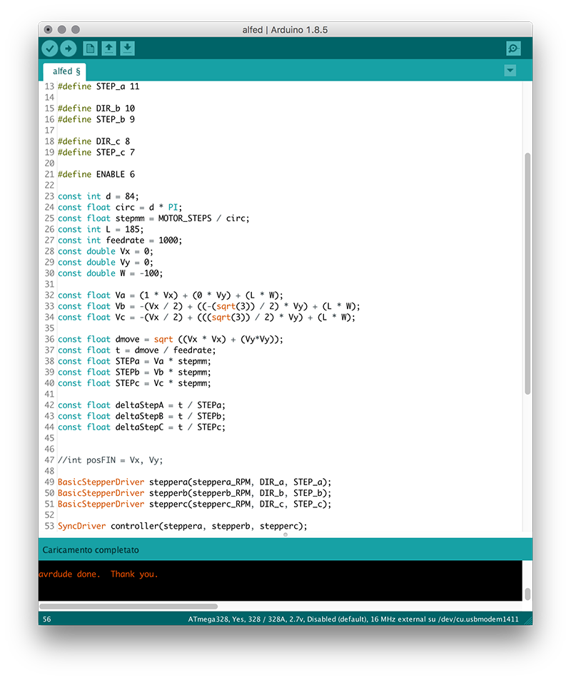
At first I found a sketch already made of a robot with three omnidirectional wheels but, on my board, it did not work (I think because it was written for a different type of board with different components). Not being able to find anything that was right for me, I started looking for sketches and bookshelves to be joined to be able to move the three wheels at a given point.
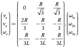
After finding the right libraries, I wrote the inverse kinematics matrix that is usually applied to the movements of robotic arms.
 Close
Close
Initially, the idea for the Final Project was to create a device for making room measurements. The idea was to use motion and distance sensors to track the path in the rooms and the distance of the walls from the device. It was a nice idea but not funny enough. So I decided to change the project while keeping the motion and distance sensors as the central element.

Discussing with Enrico, we came up with the idea of creating a table that could move thanks to the simple movement of the hands or through the use of a device. It could be a coffee table that, to make it go from one side of the room to the other (or to the nearby sofa), touches it with the hand as if to push it, and thanks to the sensors it does not hit the objects. Another use, which would be more complicated to achieve, could be that of the workbench that "follows you". Thanks to a receiver kept in a pocket the workbench with all the tools, it follows you at a certain distance avoiding all obstacles. To make the project more enjoyable we also thought that we could make a variant as a "heavy-object-carrier" which, instead of being controlled by a movement, is controlled by a drone.
Since the table must carry objects, the movement system must be designed in such a way that they do not fall down. One method is to make legs that move mechanically. There must be at least three legs resting on the ground, otherwise there would be no balance, but above all you should find a way to make it walk in all directions, and not just two.
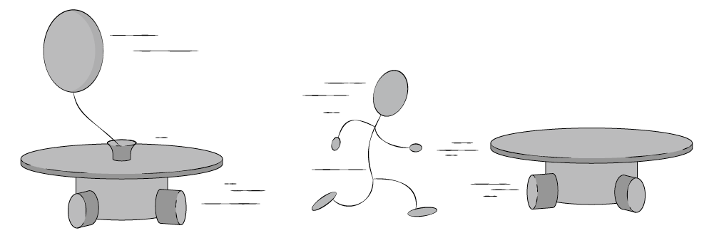
Another way would be to use wheels. With the wheels it would be easier to move the table in all directions. In this case I "stole" the idea to Goliath, a portable cnc milling machine that has 3 series of wheels made up of 3 other wheels. Each wheel has four bearings that allow it to move in multiple directions.
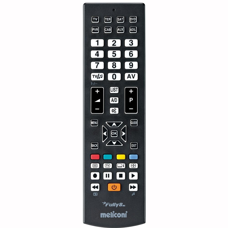
A problem could be that the motion sensors perceive anything that moves within 50cm, which would be annoying and above all the table would never stand still. The solution could be to use a universal television remote control. Some types of remote control have different keys that are used to determine which device to connect to (TV, TER, SAT, DVD, PVR, SAT, AUX, ADSL). It is difficult that all these keys are used, so my goal is to use one of these keys to activate or deactivate the motion sensors. It could also be useful to be able to assign other remote control functions to make things happen at the table.
 Close Project
To create my personal website, I initially had several problems. I've never done a website, and for work reasons I had difficulty following the first lessons. I made a lot of mistakes, including trying to edit the website through GITLAB. Having generated the SSH KEY and done all the first operations on GITLAB has created a kind of loop that making confusion about the location of the files to load and download. I initially tried to solve the problem by myself, failing so I asked my teammates who have not managed to help me anyway. So at the end I asked Enrico who managed to solve the mistakes. After several unsuccessful attempts we opted to totally remove all that was loaded on GITLAB and then reload the new files. Then everything started to work.
After downloading and installing GIT and BRACKETS I was able to start with the creation of the website.
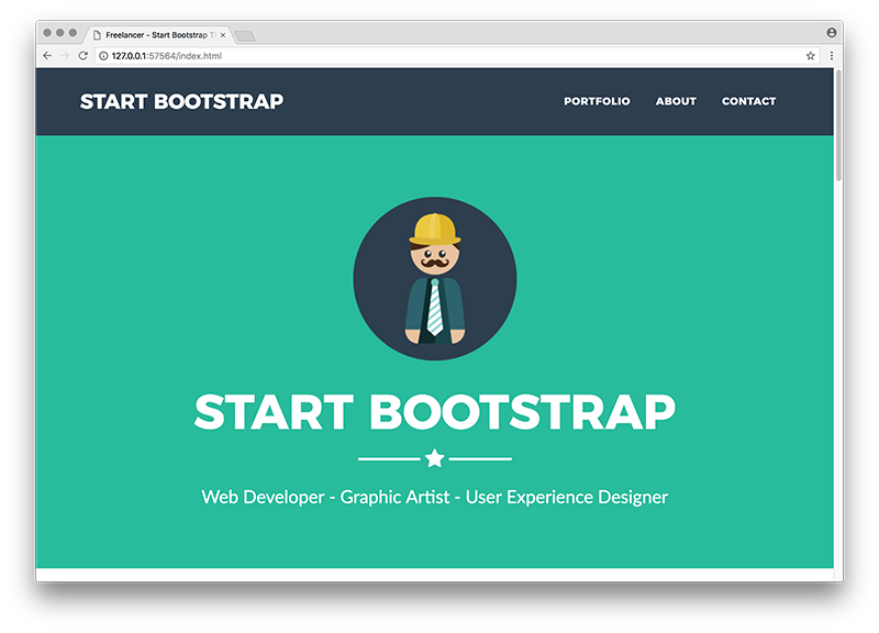
Initially I chose a template from startbootsrap.com (simple sidebar) very simple and basic with the intention to intervene and modify the skeleton, but after several attempts at modification and customization I chose to download a new tempate (freelancer).
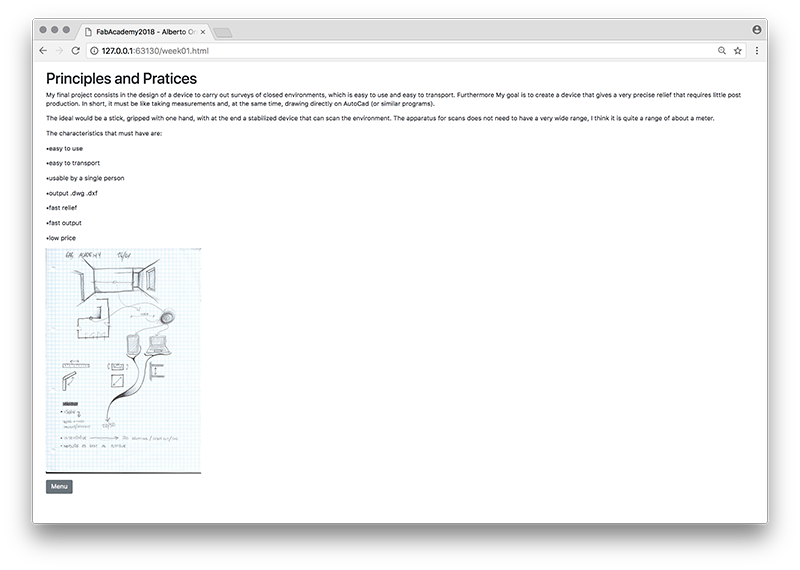 I decided to change mainly because I was difficult to make some changes to make navigation more fluid. And it's even nicer to see.
 Brackets is simple enough to use. Is a program that allows you to work offline and have a preview in real time so as to have an immediate response to the changes made. A very useful function of Brackets is the division of elements by color that allows you to read the code more simply.
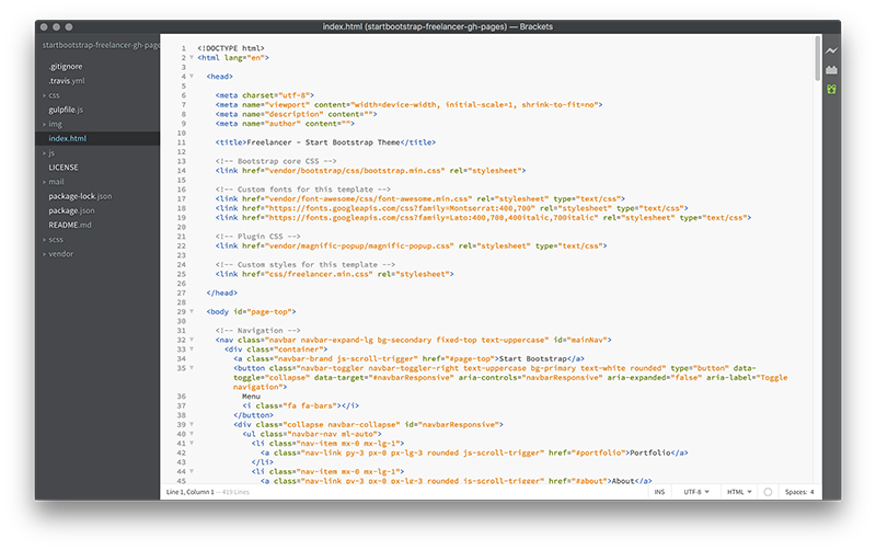 To change the individual elements is just as simple. Web sites, and this in particular, are composed of several files that contain all the characteristics that the site must have (fonts, colors, text size, alignment, etc.). They are called file.css and are linked to the INDEX.HTML file, where the contents of the site are written. Brackets allows you to edit the .css directly from the index.html page simply by clicking on the element you want to change.
 So just arm yourself with good patience and begin to modify your website making it personal.
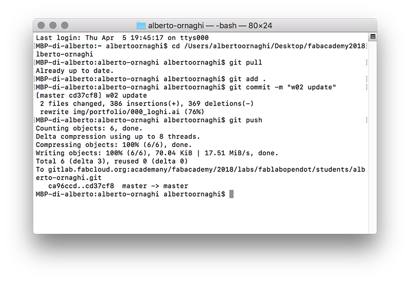
To upload the website to GITLAB I can use the TERMINAL (mac user). Given all the chaos that I created in the first weeks of Fabacademy, I created the ssh-key directly on GitLab then, once installed correctly Git, I simply had to enter my login data:
Finally, to upload the edited files of the website, simply follow a simple procedure by typing the following codes on the terminal:
Typing these codes we basically said to communicate with the folder that contains all the files on the website (cd "folder path"), to check what is loaded on GitLab (git pull) and to add all the files that are been added or modified (git add .). Then we left a comment with writing what we changed (git commit -m "commit") and finally we uploaded the files to GitLab (git push).
 Close Project
For the realization of computer drawings there are programs that are divided into two macro groups: 2D drawing and 3D drawing. In turn, these two categories can be divided into two other categories each. 2D software can create raster and vector images, while 3D software can be used to create solids through mesh or polygons and be parametric or simply for modeling.
These categories give us the possibility to choose between a vast number of programs that are more suited to the work we have to do.
I tried to test some software proposed by Neil.
2D RASTER
Krita: it's a fairly simple software to use, with very basic commands. It allows to perform the post-production of photos and to draw freehand shapes or lines of any kind. There should also be a way to draw in vector but I could not find the right command.
Photoshop: is the program par excellence for photoediting. For this reason it is a very vast program full of commands. The lapel of the coin is that it is complex enough to use.
2D VECTOR
Illustrator: unlike Photoshop I found it much more intuitive with very intuitive commands. You can create vector images that can be used for printing (flyers, postcards, posters), illustrations and also wanting "technical" drawings, but only in cases where millimetric precision is not required (example: file for the vynil cut).
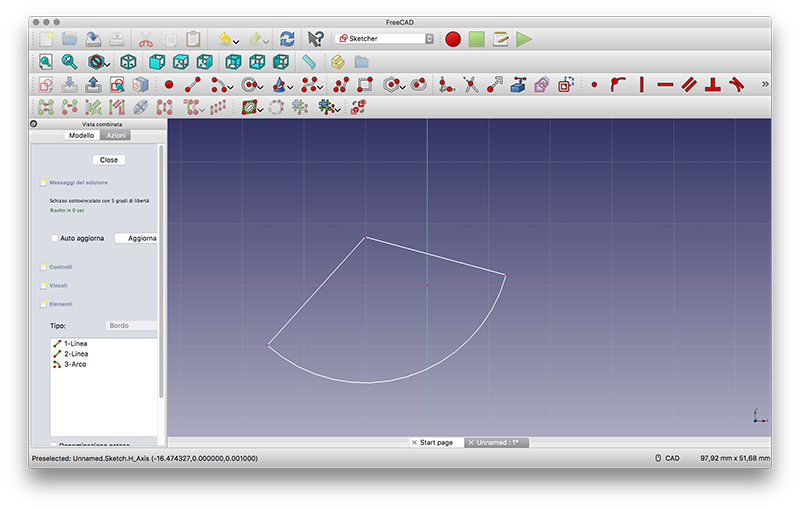
FreeCAD: I tried Freecad for at least an hour and I felt like I had never used a design software of any kind. I even struggled to make a rectangle. I do not understand if they are the icons in cartoon style or the left on the left that disturb the understanding of the software.
3D
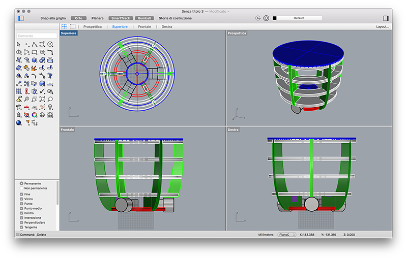
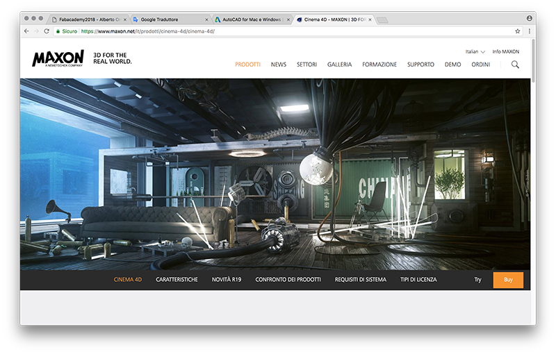
Cinema 4D: in my opinion it is a very intuitive and easy to use program, and at the same time very vast. You can model very complex objects consisting of meshes and polygons, make motiongraphics, animations of characters and objects, perform photorealistic renderings and "comics" effects. In addition, all elements of the project can be conveniently managed in a window with the construction history.
Rhino:at first use it is quite simple to use to make 2D and 3D drawings, but the more you use it, it becomes more and more technical and complete, until you have a mechanical precision of the drawings. Only the parametric functions would be missing.
It helps a lot its simplicity and the layout of the viewports that move from 2D to 3D visualization in a very fast way. Finally the icons are quite intuitive.
Fusion 360: very few times I have used a parametric program, but Fusion 360mi seemed really complete. I found it very difficult to use, certainly you will be able to exploit its full potential after different usage time.
It is excellent for mechanical design as it can combine several parametric files into one.
Finally it has an excellent CAM that can export files for many CNC machines.
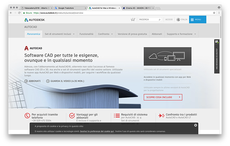
AutoCad: is the most common technical drawings program. For this reason, if you need to send files that will have to be edited by another person, the best and safest thing is to do it using AutoCad.
It also has a part of 3D modeling but I honestly did not feel good. In my opinion it is due to the fact that it has such a huge choice of commands for the realization of 2D technical drawings that struggle to coexist with the 3D modeling commands.
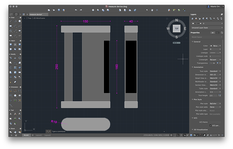
To design the possible final project I decided to use two very used software in the design field.
For the technical drawing in 2D I used AutoCAD of the Autodesk package, while for 3D drawings I used Cinema4D (Maxon).
To draw on AutoCAD I used a few basic commands
• rectangle: you can use this command in different ways depending on the design you want to do. Once the command has been selected, you can type the Cartesian coordinates to indicate the first point (which will be the lower left corner), separated by a comma, or you can simply click anywhere in the workspace. The second point (top left) can be determined in different ways. The first method is to insert Cartesian coordinates (to be precise you must have entered the coordinates or know exactly the position of the first point). If the position of the first point has not been defined with precise coordinates, you can enter the size of the rectangle you want to insert first the dimension of the horizontal (X) and then the vertical (Y) sides, both preceded by the scroll and separated by the comma (@XXX, YYY).
• polyline: the polyline command allows you to create closed paths composed of lines and arcs. As with the rectangle, you can determine the first point by entering Cartesian coordinates or by clicking on a random spot in the workspace. Afterwards the following points can be determined in the same way: you can enter the coordinates or determine with the mouse pointer the direction of the point with respect to the one drawn previously and enter the length of the segment. Finally you can easily switch to "arc" mode by pressing the right mouse button.
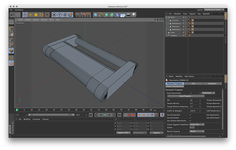
And this are the comends I used to draw in Cinema 4D
• box: by default when you click on the cube creation icon, this is created positioned in the 0,0,0 point of the workspace with a side of 200cm. The pivot of the cube is exactly at the center of it. In the object properties window you can internally on the characteristics of the solid, including the dimensions and in how many parts divide the six faces of the cube.
To change the solid you have to select it and click on "make the object editable" (shortcut C). In this way it is possible to intervene on any part of the solid (points, sides, faces) for a free transformation. Only now can the Chamfer instrument be used.
• chamfer: to make a connection between two faces, the chamfer tool is used. To use it you must first enter the edge selection mode, select the edges that you want to chamfer and click on the chamfer button (shortcut M-S). Now in the command of the control panel can decide what kind of chamfer do (linear, concave, convex, bezier, user) and how to do it.
All solid edit commands work the same way. Just select the parts you want to change (points, edges, faces) select the command and change the values from the properties panel.
Conversion tools work differently. As an example let's see how we do operations between solids:
• booleane: when you want to combine, subtract or find the intersection between two solids, using the Boolean tool. To do this, simply select the command and the icon appears automatically in the "object management" window. Always from the "object management" window we just select and drag the objects we want to modify onto the Boolean icon. Unlike programs like Rhinoceros, we can continue to change both the order of solids (example: which solid is subtracted from the other solid) and the position of one solid relative to the other, without having to go back (ctrl + z), change order and position and call the command.
During the course of the FabAcademy both the project and the software used have changed.
I learned to use Rhino which is a fairly complete software. It allows to realize technical drawings both in 2D and in 3D, managing to control all the dimensions with an excellent precision.
GROUP PROJECT
Characterize your lasercutter, making lasercutter test part(s), making test part(s) that vary cutting settings and dimensions(group project)
OpenDot Group Page
LASERCUTTER
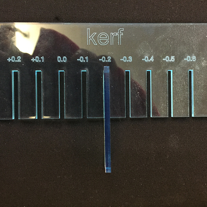
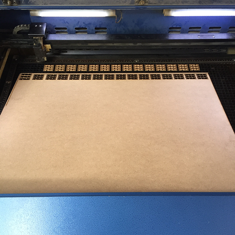
The cut, though it may be fine and precise, burns and steals the material, so you have to do some tests to actually verify the difference in order to have perfect joints.
In my case I tested on a 3mm plexiglass. The result is that the laser has raised 0.2 mm of extra material, so in the drawing I have to make an offset of 0.2 mm lines to the outside.
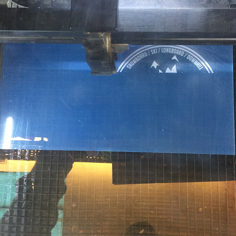
After importing the files on Rhinoceros, I divided the lines and paths into different layers depending on the characteristics: cutting, vector engraving and raster engraving.
The three layers differ mainly due to the speed of the laser, keeping the power to the maximum. Naturally, the speed of the laser will be adjusted according to the complexity of the design and how deep the incision is to be made.
From Rhinoceros I set the following parameters:
CUTTING - speed = 2, power = 100
VECTOR - speed = 40, power = 100
RASTER - speed = 40, power = 100


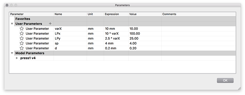
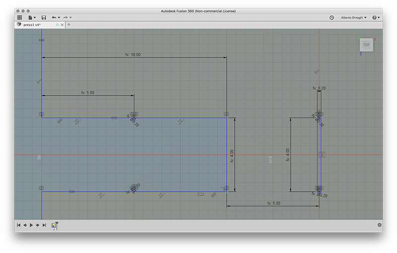
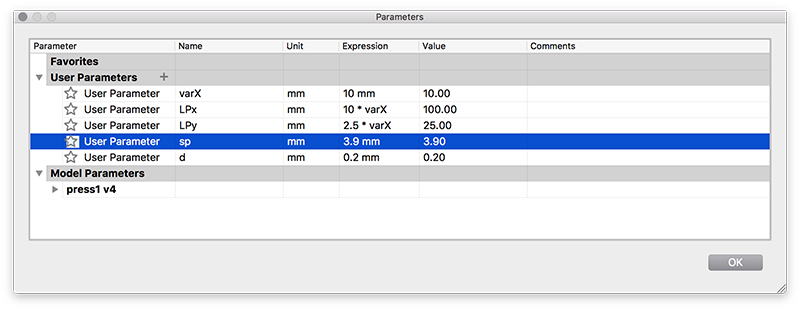
Realize a parametric drawing means to assign values of the variables that can be changed from the outside, and which may be all in relation to each other. So it is enough to change one of these values that changes the whole project, maintaining the established relationships and relationships.
In my project I decided to use only one measure on which the proportions of the single piece depended. So I set a variable X (varX) as the only measure to be changed for proportions of the final piece and on which the other two measurements depend (height = LPx = 10 * varX, width = LPy = 2.5 * varX).
Then I added two more variables. The variable thickness (sp) of the material that will be laser cut and the diameter (d) of the semi-circle that will serve to lock the pieces of the press-fit kit.
Being able to change the thickness value is fundamental because it allows to constrain in a single value all those parts of the project that depend on the thickness of the material that will be used. If this operation is not done, much of the design should be changed by hand, risking making mistakes.
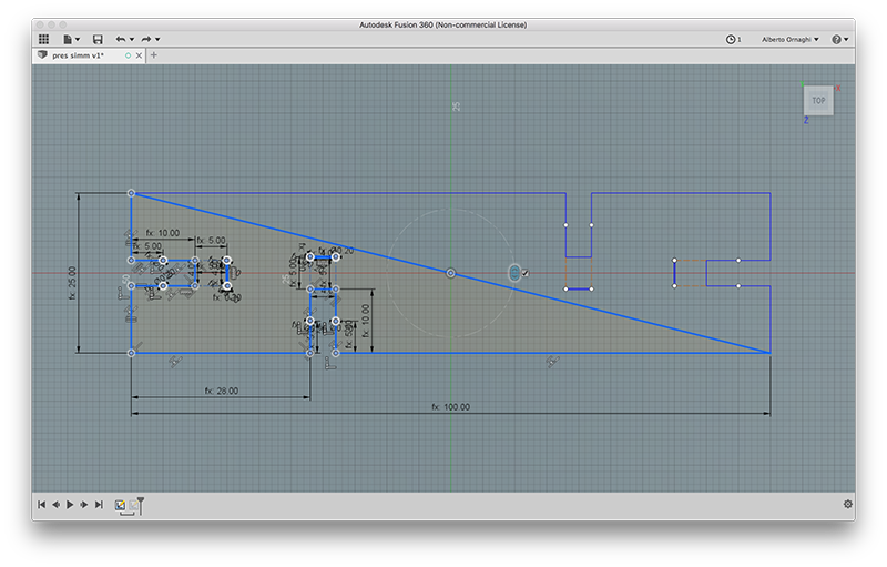
After making a pencil drawing, I realized that I could only draw half of the final object, as I would have done exactly what I had designed by making a 180 ° rotated copy.
First I drew a triangle with the hypotenuse passing through the 0,0,0 point of the work space and binding it to the midpoint of the hypotenuse. In this way every time any parameter is changed, the midpoint of the hypotenuse will always be coincident at the point 0,0,0.
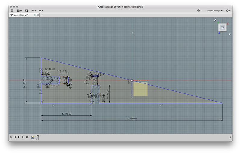
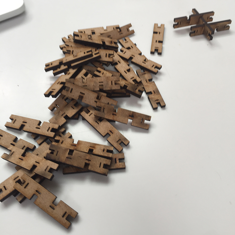
Finally I designed the parts for the press-fit, using the previously stated variables of thickness and diameter, using a simple pressure joint.
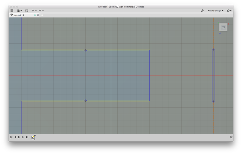
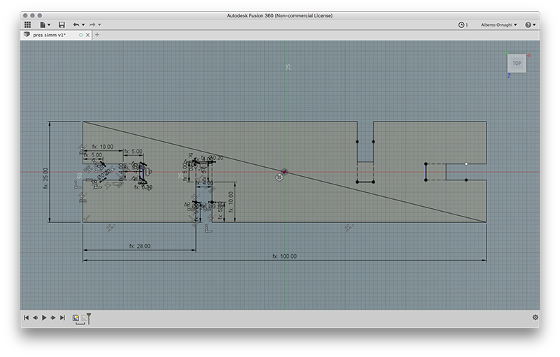
Making a copy rotated 180 ° with the center of the rotation at the point 0,0,0 (which coincides, as said before, with the midpoint of the hypotenuse) I got exactly what I wanted.
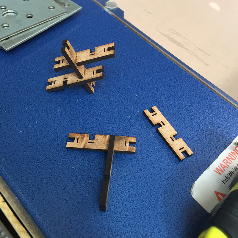
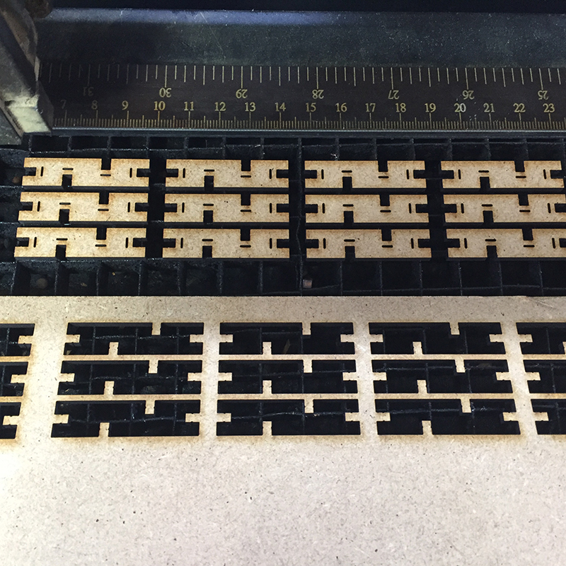
Before cutting all the necessary pieces I performed a test to verify that the pieces actually fit perfectly.
I cut three pieces and in fact were very badly interlocked, the seat of the joint was too wide.
It was enough to go back to Fusion and slightly decrease the thickness parameter, bringing it from 4mm to 3.9mm. I cut three more pieces of evidence and once they were stuck they coincided perfectly.
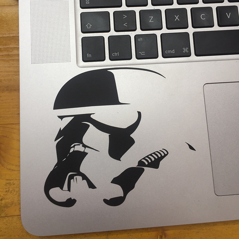
VINYLCUTTER
The vinyl-cutter files are very simple to make. You can use programs like Illustrator, AutoCAD or Rhinoceros, just create a vector drawing and export it to DXF.
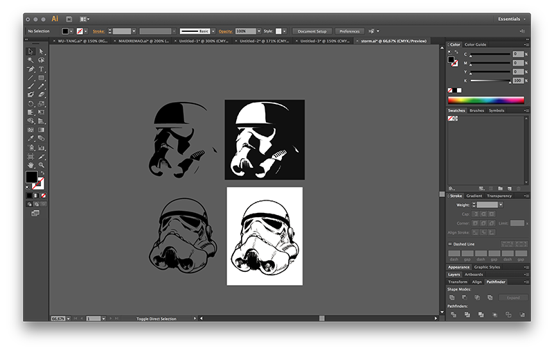
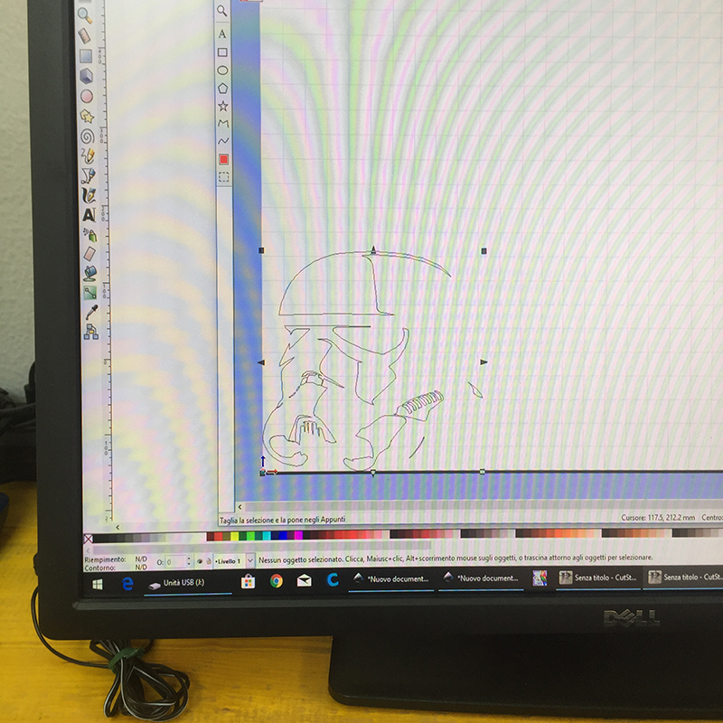
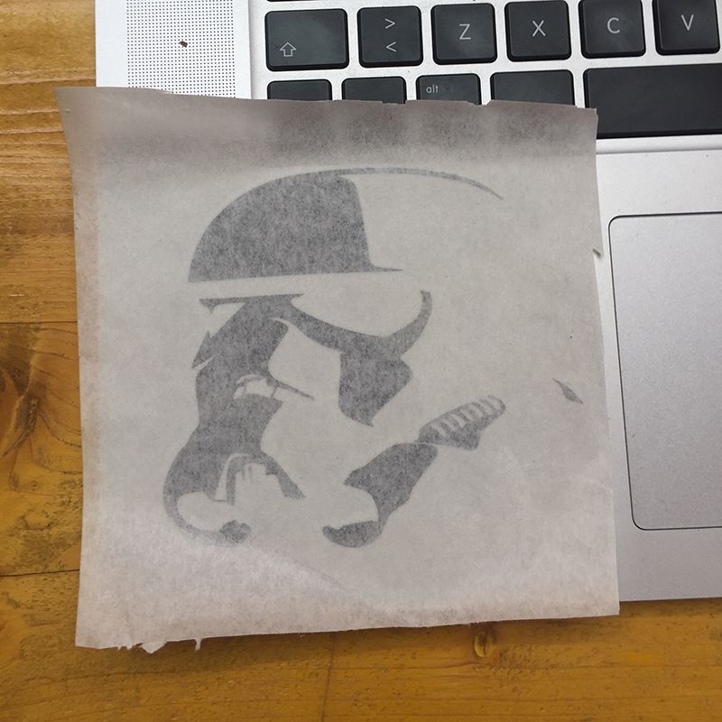
To test the potential of the vinylcutter I decided to start from a .jpg image already made (also to add an extra step so far not documented).
The ideal for vinyl-cutter is to make or use fairly simple vector images.


I downloaded two raster images with a strong contrast between whites and blacks, and I imported them into Illustrator to vectorize them.
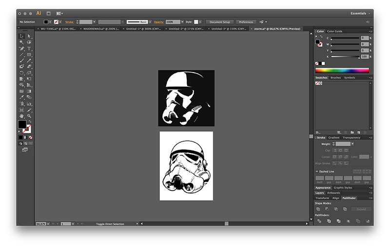
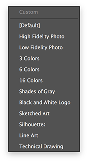
Selecting the images, on the upper bar, the "Image Trace" button is used, which allows you to trace the boundary lines between one color and the other, following the parameters. In the drop-down menu that appears you can select the type of source image that was imported for an optimal result.
In this case it was enough for me to click on "Black and White Logo", and that's it.
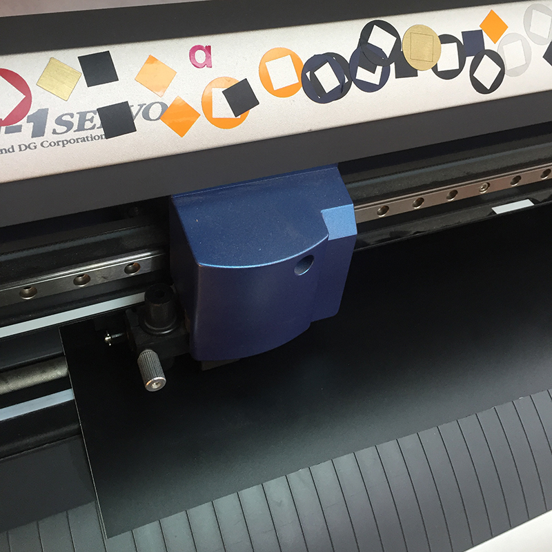
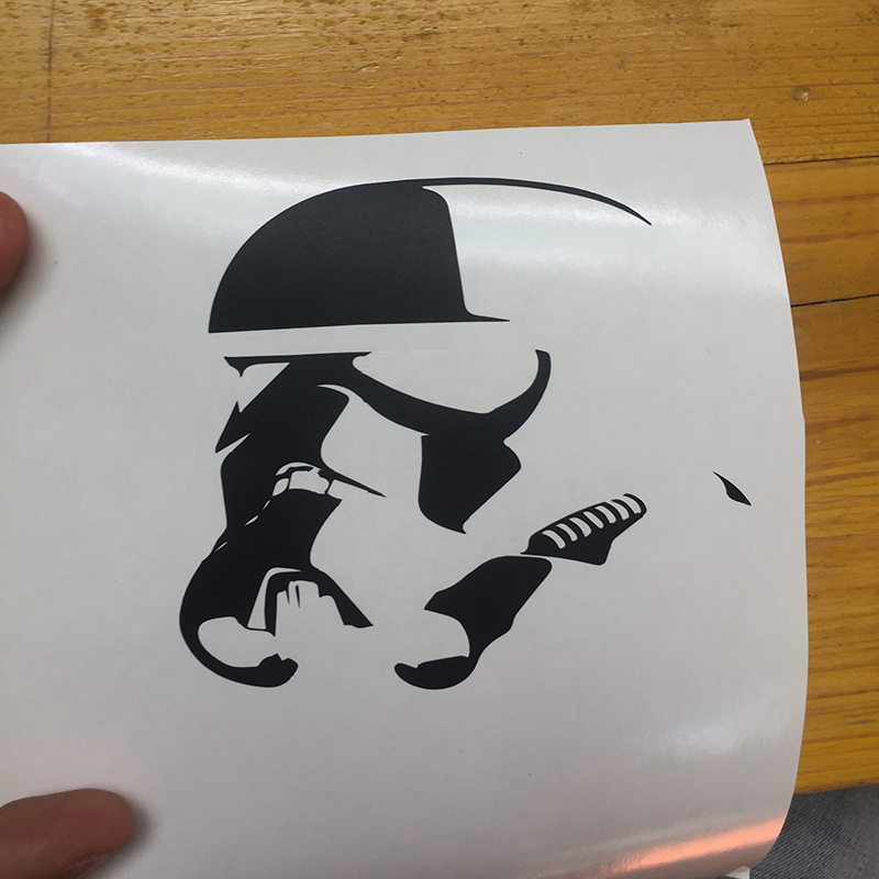
Before starting to use the vinyl cutter, it is good practice to do a blade force test. it is possible that each vinyl has different thicknesses and finishes, so the blade behaves in different ways, and a test eliminates all doubts.
Once the vector file has been exported to .dxf, using the vinyl cutter is very simple.
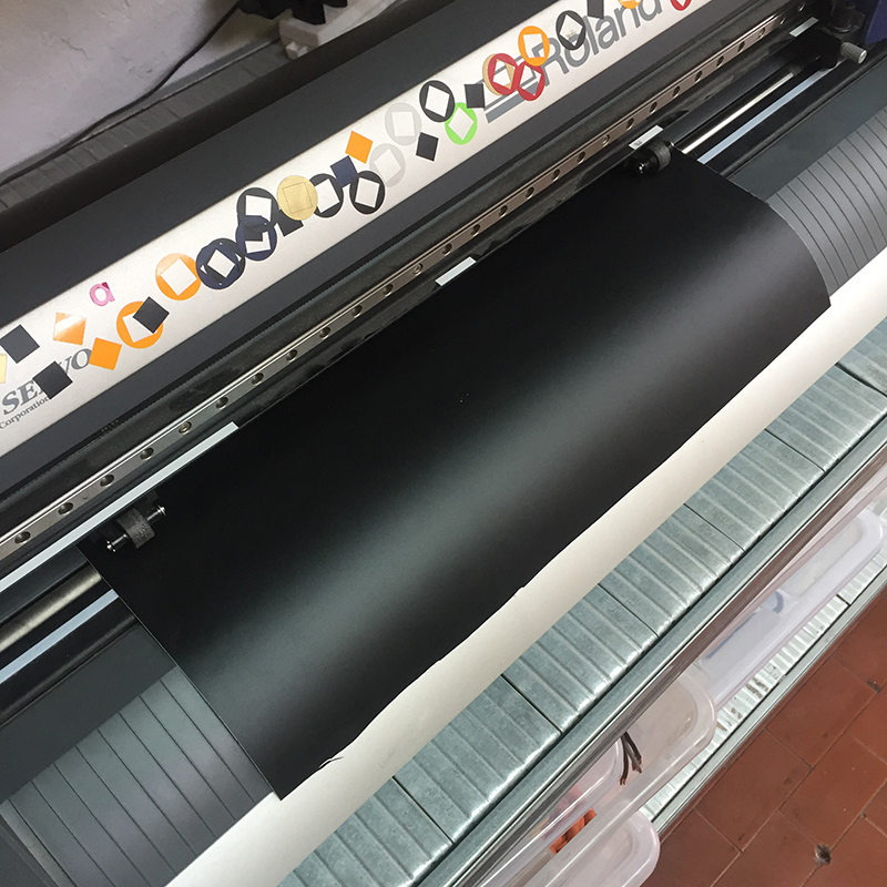
1 - turn on the machine
2 - place the roll or the vinyl sheet behind the machine
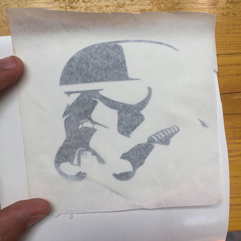
3 - raise the lever on the left and insert the sheet
4 - align the sheet with the white markers and the vertical lines
5 - place the sheet-stop wheels under the white marks near the edges of the sheet
6 - lock the lever
7 - from the screen of the machine choose between *roll and *piece
8 - perform the zeroing with the arrows
9 - press "origin" until "origin set" appears
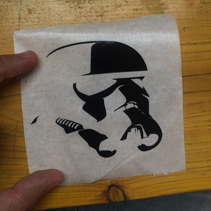
10 - open the .dxf file on inkscape
11 - click on "extensions> roland cut studio> open in cut studio"
12 - click on "file> cut setting" and "printer: roland GX-24> property> get from machine" to have the zero position and the sheet size
13 - cut
 Close Project
GROUP PROJECT
Characterize the specifications of your PCB production process
OpenDot Group Page
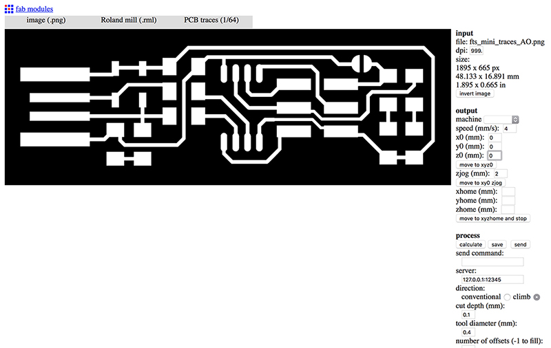
After downloading the test file ( trace cut), we have upload on fabmodules to edit and create the files that will then be inserted into the CNC milling software.
On FabModules:
• input format -> image .png and load the image (check that the dpi is at 1000 because being a raster image therefore must have a very high definition);
• output format -> roland mill (.rml) and set "MDX-40" as machine;
• process -> PCB traces (1/64) or PCB outline (1/32);
• set the x, y and z origin as zero;
In the "process" section you need to set the machine parameters:
• cut depth (mm): indicates the depth of the incisions that will make the cutter
• tool diameter (mm): indicates the diameter of the cutter
• number of offset: indicates the number of external offsets that the cutter performs around the geometry
After loading the .rml file on V-Panel, you need to set the origin of the X, Y and Z axes. To set the values of the X and Y, you can make an eye position, while for the value of the Z you need to use a craft device (available in the laboratory) consisting of a magnet and a clamp. Once the clamp on the cutter and the magnet on the PCB board are positioned, the cutter is very close to the board by means of the software. As soon as the led connected to the device starts to flash, it means that the circuit is closing, therefore the value of Z can be set.
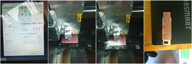
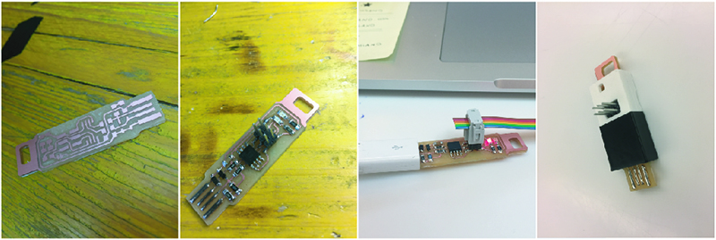
After removing all the pieces of excess copper, I can proceed with the welding phase.
The necessary components are:
• 1x ATtiny45 or ATtiny85
• 2x 1kΩ resistors
• 2x 499Ω resistors
• 2x 49Ω resistors
• 2x 3.3v zener diodes
• 1x red LED
• 1x green LED
• 1x 100nF capacitor
• 1x 2x3 pin header
After having soldered all the components to the board, you can proceed with programming using this
tutorial.
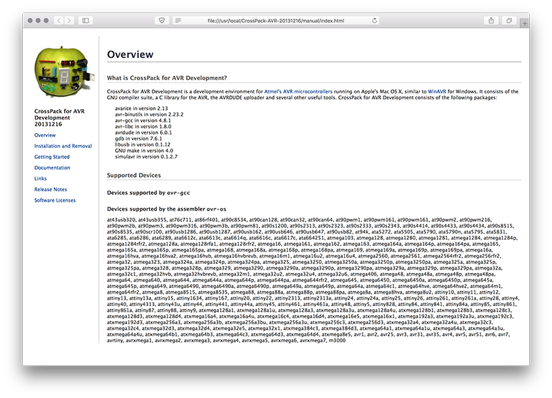
To program my FabISP I first downloaded and installed CrossPack for AVR.
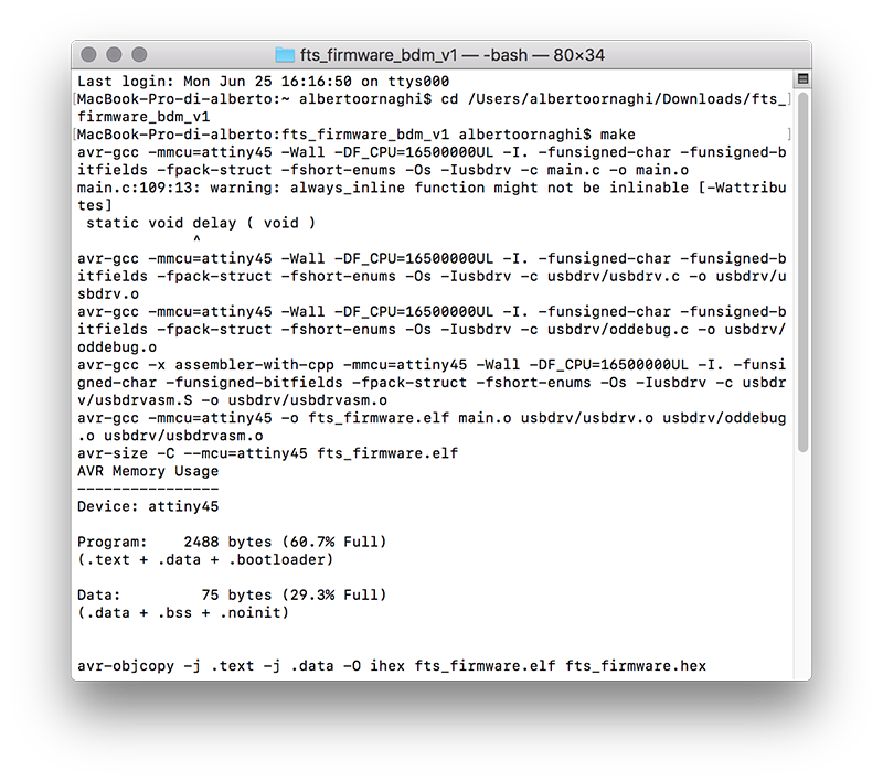
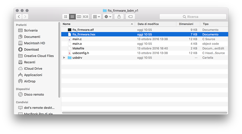
To build the firmware you need to download this source code firmware. After downloading and unzipping it, just open the terminal (mac user) type "CD-folder path-" and press enter.
Then type "MAKE" and press enter. After the command completes the operation, a file will be created in the folder called "fts_firmware.hex".
After connecting my FabISP to another programmer and to the usb port of my mac, I typed, always on the terminal, the command MAKE FLASH. Thanks to this command, the .hex file previously created is uploaded to my programmer.
Now we just have to check that the procedure has been successful.
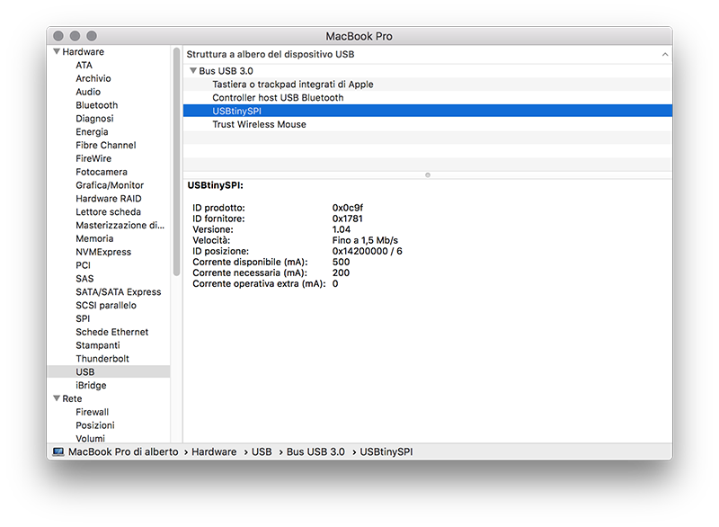
Open the "information on this mac -> system report" window and in the USB menu you can find my FabISP under the name "USBtinySPI".
 Close Project
GROUP PROJECT
Test the design rules for your printer(s)
OpenDot Group Page
3D SCANNING
As for the scanning of an object, I opted for photogrammetry.
This technique is not easy to do, not for the use of image processing software, but for the quality of the photos.
Photogrammetry provides for the capture of different photos from various angles, which are then processed by software that sorts them and manages to create a mesh of the photographed object.
The problems I found in taking pictures are different. First of all you must have a well-diffused light, with few parts in the shade, but not even a light too flat otherwise the surfaces are not perceived.
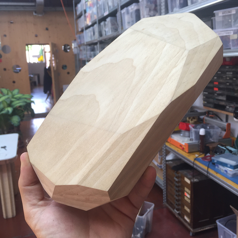
The object will be perceived better if it has an opaque surface such as the support where it is placed. In the first tests I used an orange rubber sheet, which was too confusing with my wooden object, in fact the processing of the photos was not optimal. As soon as I swapped the orange material with a similar but white, the result changed considerably.
The perfect light conditions would be when there is a lightly cloudy sky, when there is enough light to illuminate objects well but not too much to create too strong shadows.
For photogrammetry the two most popular software are Zephyr and PhotoScan. Zephyr is a program that can be installed on Windows platforms, while PhotoScan, in the demo version, does not allow to export or save projects. I started processing photos with PhotoScan (and later on I borrowed Max's PC to be able to export the model).
 To get a 3D model from the photos you have to follow a series of steps in sequence (
tutorial:
To get a 3D model from the photos you have to follow a series of steps in sequence (
tutorial:
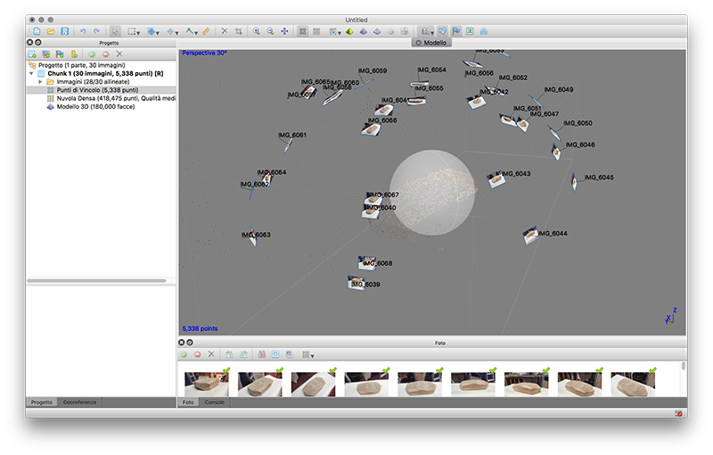
- Align Photos = At this stage PhotoScan refines the point cloud model.
 - Build Dense Point Cloud = Based on the estimated room category the program calculates the information needed to be combined into a single dense point cloud.
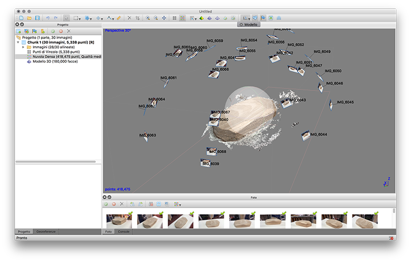 - Build Mesh = After the cloud has been reconstructed it is possible to generate a polygonal mesh based on the dense cloud data.
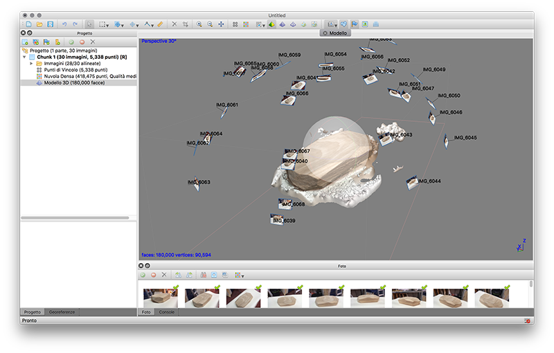 - Build Texture = This step could be skipped if untextured model is sufficient as the final result.
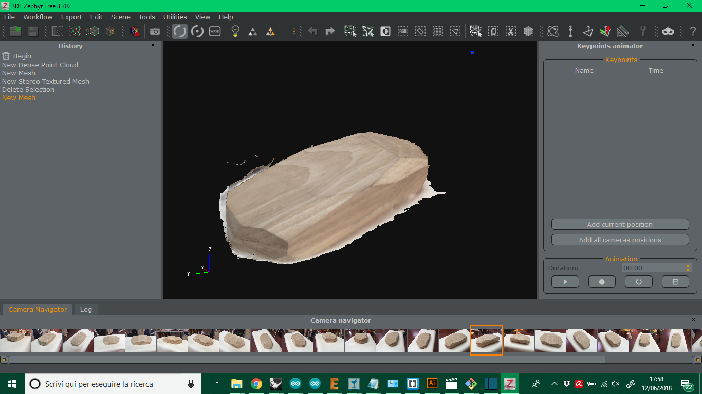
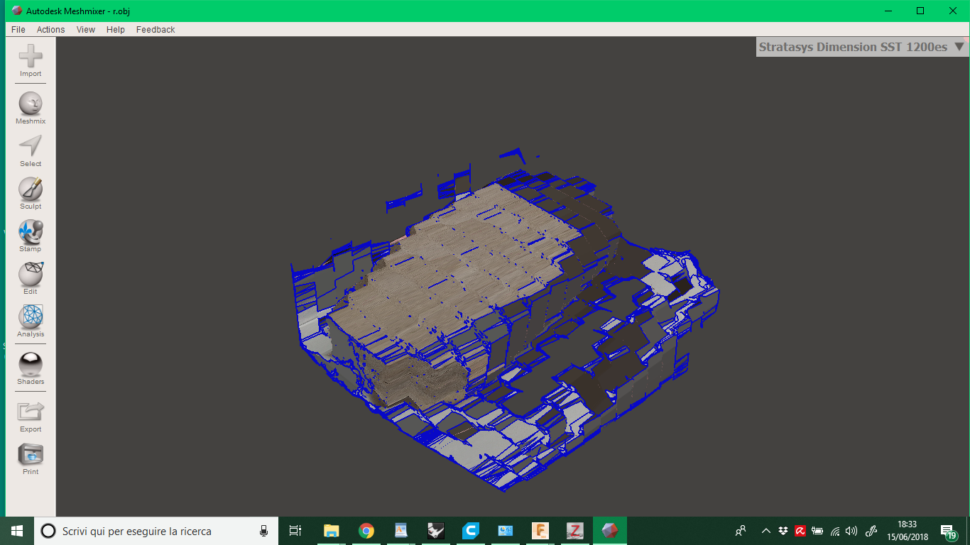
After learning how to use Zephyr, which works exactly like PhotoScan, I exported the model to edit it with Mesh Mixer.
I do not know why but, once imported into Mesh Mixer, the mesh was totally different from the one processed with Zephyr, as if the resolution had drastically decreased. I have also tried different types of export but nothing has changed.
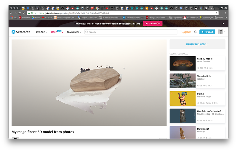
Or you can see the model on
SketchFab.
3D PRINTING
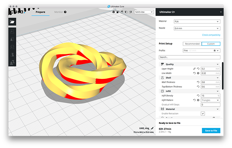
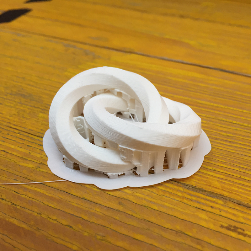
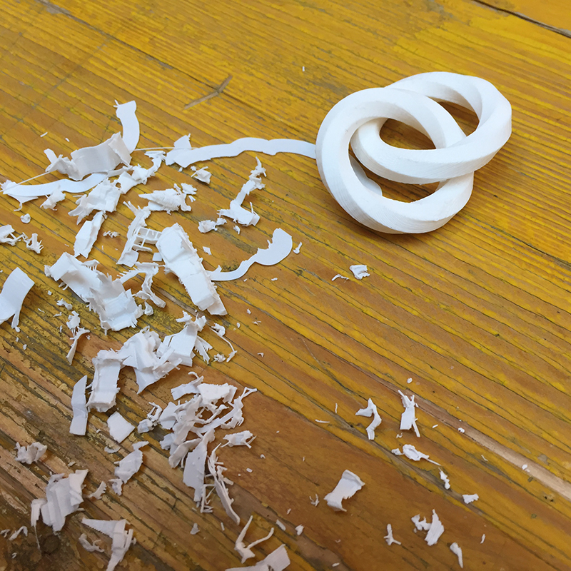
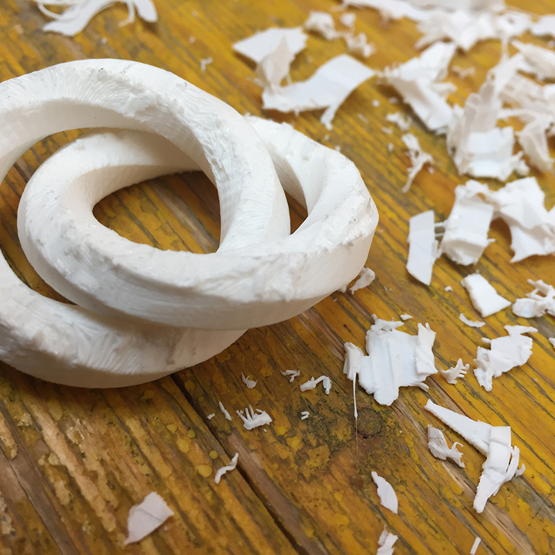
To make an object that could not be done with the subtractive technique, I modeled two rings chained one into the other with a hexagonal section that twists on itself 360 °, using Cinema 4D. I exported the model in .stl and imported it into Cura.
From the menu on the right of the window I have the possibility to change all the parameters.
The main ones are:
- Material = set the type of material
- Nozzle = set the nozzle diameter
- Layer height = must always be less than the nozzle diameter
- Line width = must always be less than the diameter of the nozzle
- Wall thickness = must be a multiple of the nozzle diameter (nozzle = 0.4 - wall thickness = 1.2 -> 3 layers on walls)
- Top / bottom thickness = must be a multiple of the nozzle diameter (nozzle = 0.4 - wall thickness = 1.2 -> 3 layers on top and bottom)
- infill density = percentage indicating how much to fill the internal space of the model
- support = if there are elements of the cantilevered model, the supports allow them to be made and can be easily removed
- build plate adhesion type = allow you to print additional parts to prevent the model from detaching from the plate during printing
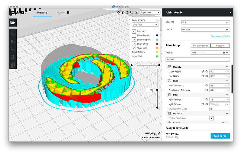
After having imported the model in Cura, the geometry presents different colors. Red colored surfaces indicate all those parts of geometry that may present problems during printing. They are all those surfaces that are in a certain range of inclination. In fact, from what we have tested in the group assignment, the surfaces below a 45 ° inclination of the printing problems.
Scrolling from top to bottom of the print parameters we must first decide how much will be the amount of material that will be extruded with each pass.
These parameters will affect the quality of the print. With a 0.4mm nozzle we set the height of the layer and the width of the line. As the width of the line it would be logical to indicate the same value of the nozzle diameter, but since the extruded material (in our case PLA) just out of the nozzle will have a minimal expansion, I set 0.32. So the difference of 0.08 tenths will be compensated on the two sides by the expansion of the PLA.
Once this is done, the wall thickness and top / bottom values are entered.
Usually (apart from exceptional cases) these values will be multiples of the height of the layer (top / bottom) and thickness of the line (wall thickness).
Finally imposed how much the object must be full. It would be better to fill them all the time because in this way we provide a structure on which all the external layers know how to support, improving the finish of the final object. It must be said, however, that it is not always positive to increase the filling too much, because it increases printing times (and costs) in an unnecessary way. A fair average value is around 15%.
Now I'm going to set the parts that, once the printing is over, will be removed and that are useful for the realization of particular objects, as in my case two rings that do not have flat surfaces to lean on.
To do this, you generate supports that work like a scaffold. In this tab you set where and under what surfaces to put the support. I set them to put them under all the surfaces that went from an inclination from 5 ° up.
And then you choose how much offset from the surface of the object to leave.
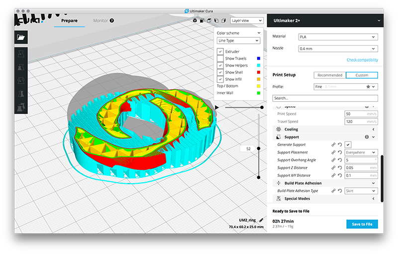
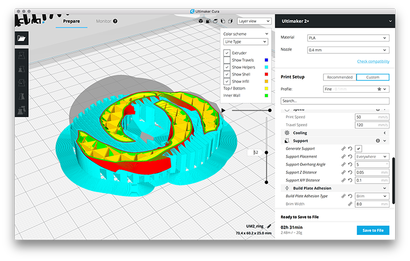
A last useful parameter to set is the adhesion to the plate. It can be used for different purposes. A SKIRT type is usually used to clean the nozzle from residues of previous processes.
I used a BRIM plate adhesion that creates a surface that is wider than the thickness of a layer to avoid the risk that during printing the object will move or come off the plate.
 Close Project
GROUP PROJECT
Use the test equipment in your lab to observe the operation of a microcontroller circuit board
OpenDot Group Page
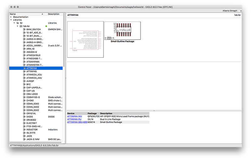
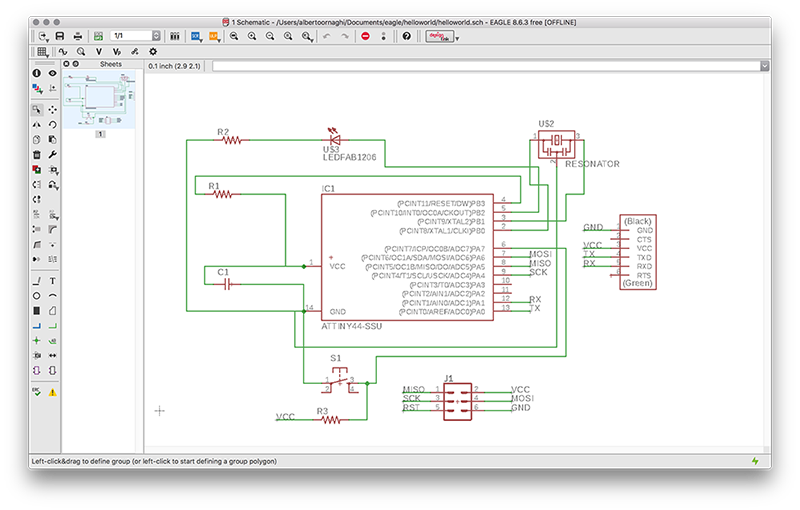
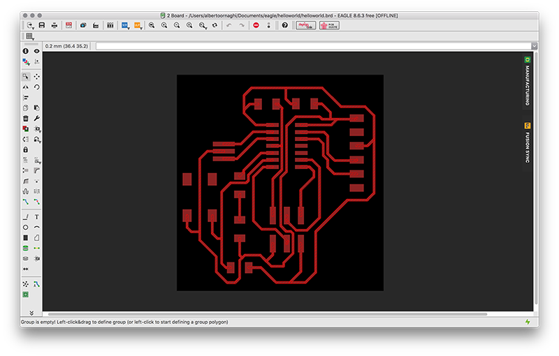
To redesign the "echo hello-world" card, I used Eagle from the Autodesk package. It is a program that allows you to draw and design cards. The advantage is that the schematic can be realized in parallel to the board, so all the components that are inserted in the schematic are also inserted "physically" in the board. The same goes for the connections between the components. By default, Eagle does not have a component library, so we downloaded it and loaded it into the control panel window. The library contains the information of some components which include in addition to the technical characteristics, also the physical dimensions and the dimensions of the footprints.
Now we are ready to redesign the "echo hello-world" card. From the control panel window a new folder is created in the "projects" drop-down menu, and the schematic window will open automatically. Within this window we can insert all the components we need, taking them from the previously loaded library. The order is relatively important because the connections between the different components can be two separate segments, the important thing is that they have the same name. So to have a more orderly schematic just draw small segments (NET) to each pin of the components and connect them virtually assigning the same name.
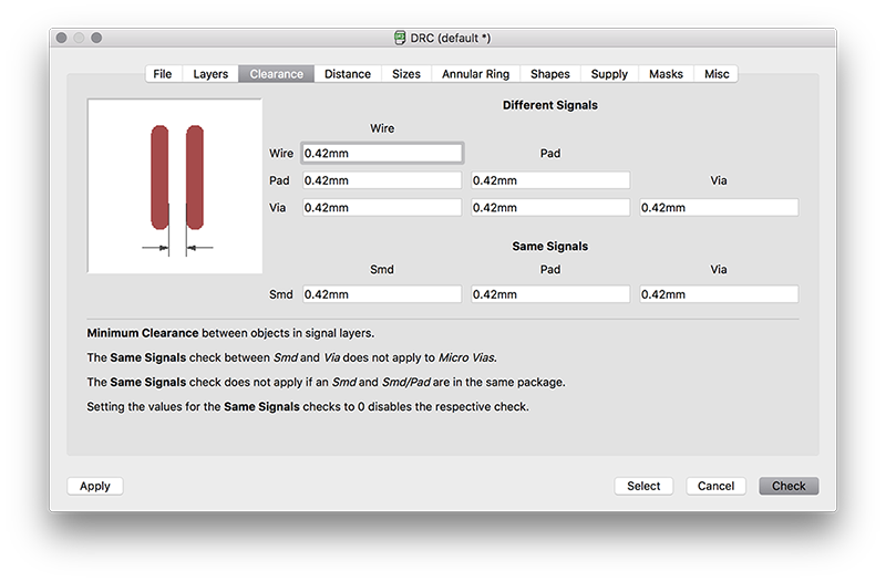
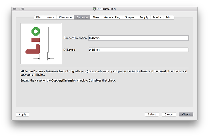
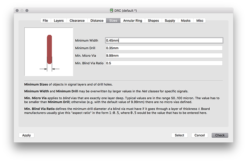
Before drawing the board, we had to set up the design rules.
After making all the connections you can proceed with the arrangement of the components and to create the paths of the tracks. For a beginner like me who does this work for the first time, is a task long enough. At the beginning I arranged the components more or less as they were arranged in the example and I designed the tracks. Then I tried to order both the components and the tracks, making several attempts, using the components as bridges to cross the tracks.
Once you have checked all the connections you can proceed with the export:
file -> export -> image
A window opens where you must indicate the path where the file will be saved and the characteristics of the output image.
Monochrome √
Resolution = 1000dpi
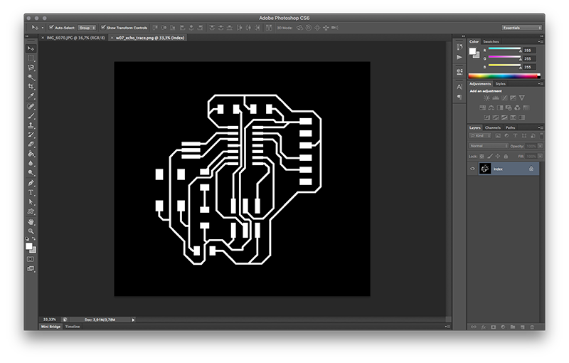
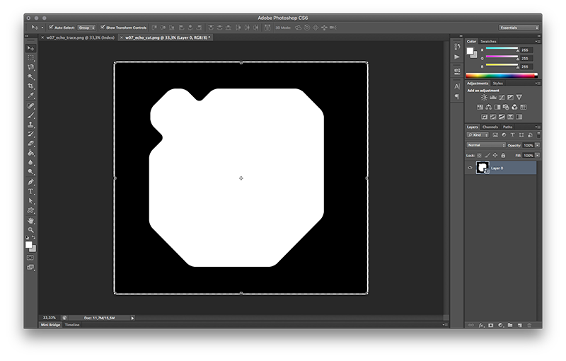
This time to outline my helloworld I decided to use Photoshop. So I imported the .png exported by Eagle and around the tracks I designed a white geometry that will be the final shape of my board.
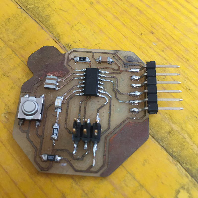
After having been milled, I have welded the following components:
- ATtiny44
- capacitor
- 10kΩ resistance
- 10kΩ resistance
- 499Ω resistance
- resonator
- ftdi connector
- isp connector
- led
- switch
 Close Project
GROUP PROJECT
test runout, alignment, speeds, feeds, and toolpaths for your machine
OpenDot Group Page
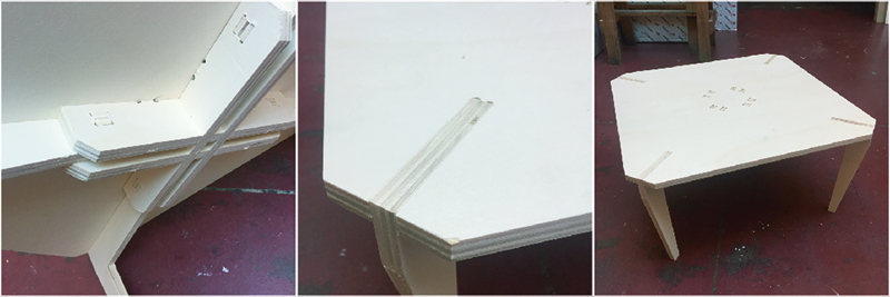
For this tutorial I designed a table. Since I'm not familiar with Fusion 360 yet, I decided to draw the table using Rhinoceros. First of all, I created a mono sketch of the table to understand and better imagine the joints that I could use. I decided to use joints that allowed me to work both 2D and 2.5D.
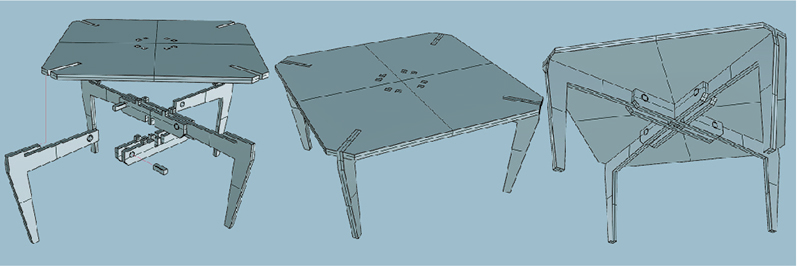
After modeling and checking that all joints and breakages went well, I switched to the table of the different pieces, always using Rhinoceros.
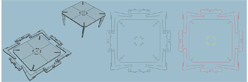
First of all, I arranged the pieces as if they were resting on a plane, with all the work done upwards. Then, with the command "extract edges" I have isolated the edges and eliminated the faces of the solid. After aligning all the elements that I needed with the same value of "Z" I divided the geometry in layers depending on the processing that I would have to match it.
Layers must be created for each type of work and for each type of cutter. For example, all machining at a depth of 7mm with a 3mm diameter drill will go in a different layer from the workings that are passing through the thickness of the material and made with a 6mm diameter drill.
• Layer pockets: for all those processes that do not go beyond the thickness of the material. A layer should be created for each machining at the same depth indicating in the layer name.
• Layer cut: on this layer are put all the processes that go beyond the thickness of the material.
After, I have exported the files to .dxf and imported them on V-Carve where you can assign the different machining operations to the geometries.
The assignment of the workings to the drawing that has just been done must respect certain hierarchies to ensure the best result of the product.
The general rule is the one that says to carry out first the workings that weaken the raw panel less. In this way the diffusion of the vibrations given by the movement of the cutter is reduced and above all there is no risk of breaking the newly machined panel, the milling cutter and the milling machine.
Mainly we have three types of machining of a CNC milling machine that are executed in this order:
1-pocket: this category includes all those processes that require removal of material without going beyond the thickness of the raw piece.
2- holes: this is a type of processing that includes the removal of small areas of material. The difference with the pockets is that the cutter works throughout the thickness of the material used.
3- cuts: in most cases the cuts are associated with the work piece outline. Being the outline, all the other processes (pockets and holes) are made inside it, so if you reverse the order of the work you risk that the piece would move and ruin all the work.
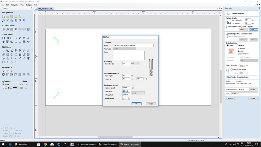
Since I decided to use a 15mm thick poplar plywood panel, I set up the workings in such a way as to do everything with the same tool.
It's a pretty soft material so I can use a 3mm milling cutter with a single cutting edge.
To make sure that the cutter does not break during processing I set a vertical pitch of 5.5mm. I chose this measure simply by finding a divider of the thickness of the material that I will go to work and adding a few tenths of a millimeter. As a stepover value for the same reason I set it to 50%, it means that at each horizontal pass the cutter makes an offset of 1.5mm (in the case of the cutter with diameter 3mm).
The speed instead I have slightly modified, lowering the feedrate from 2500mm / min to 2000mm / min, to have a better finish.
At this point it is possible to proceed with the assignment of the machining operations to the imported geometries following the order listed above.
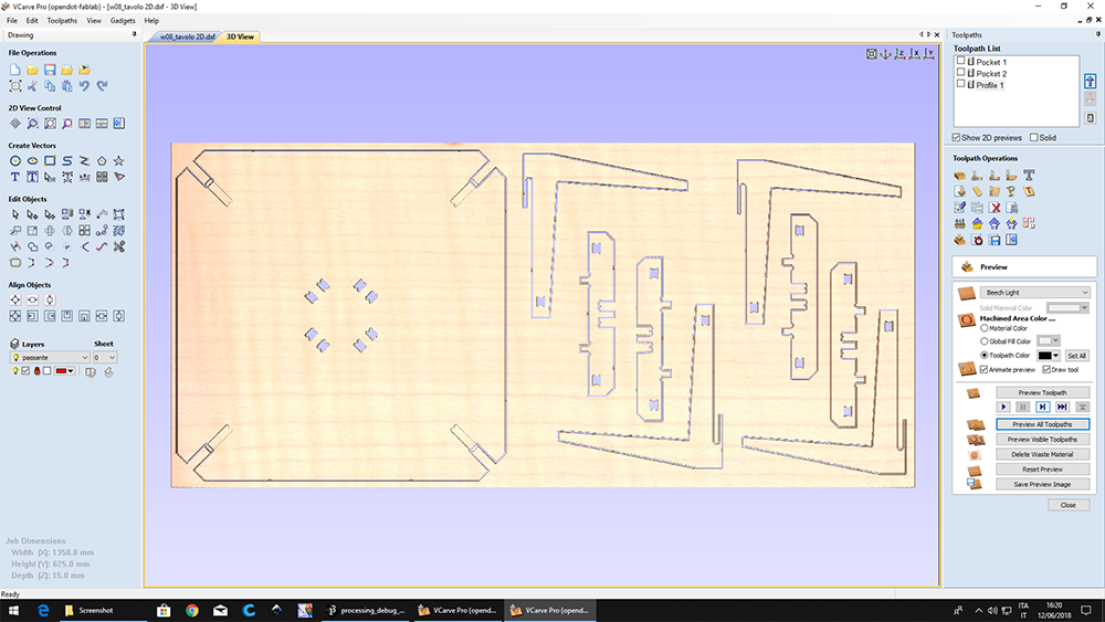
Now you have to tell the drill how to follow the paths that have been assigned to it.
In V-Carve the commands that are mainly used are "POCKET TOOLPATH" and "2D PROFILE TOOLPATH".
With the first you can make pockets and punctures, while with the second outline.
- POCKET TOOLPATH: in this type of processing it is possible to decide the working depth, which type of emptying to carry out (if at offset or raster) and the direction of the cutter (climb or conventional);
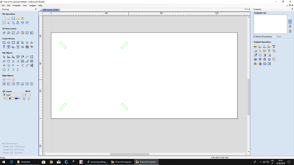
- 2D PROFILE TOOLPATH: here too we can decide the depth of machining, the direction of the drill (climb or conventional) but instead of the type of emptying we can decide whether to hold the cutter in the middle, to the right or left of the path drawn. A parameter that we find here is the addition of TABS.
The TABS are a kind of bridge or interruption of the path that do not allow the piece being worked to move, since when the outline is done the affected area is separated from that which has been fixed to the work plane.
SET THE THICKNESS OF THE PANEL
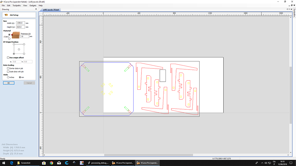
PLACE DRAWING
CHECK IF ALL THE PATH ARE CLOSED
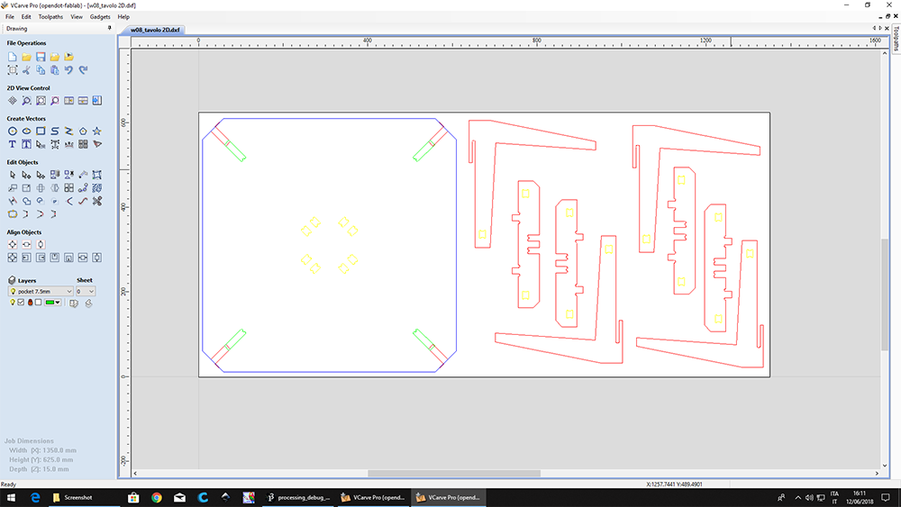
SET THE WORKINGS FOR THE POKETS
CHOOSE AND CHECK THE RIGHT TOOL
PREVIEW OF THE POKETS

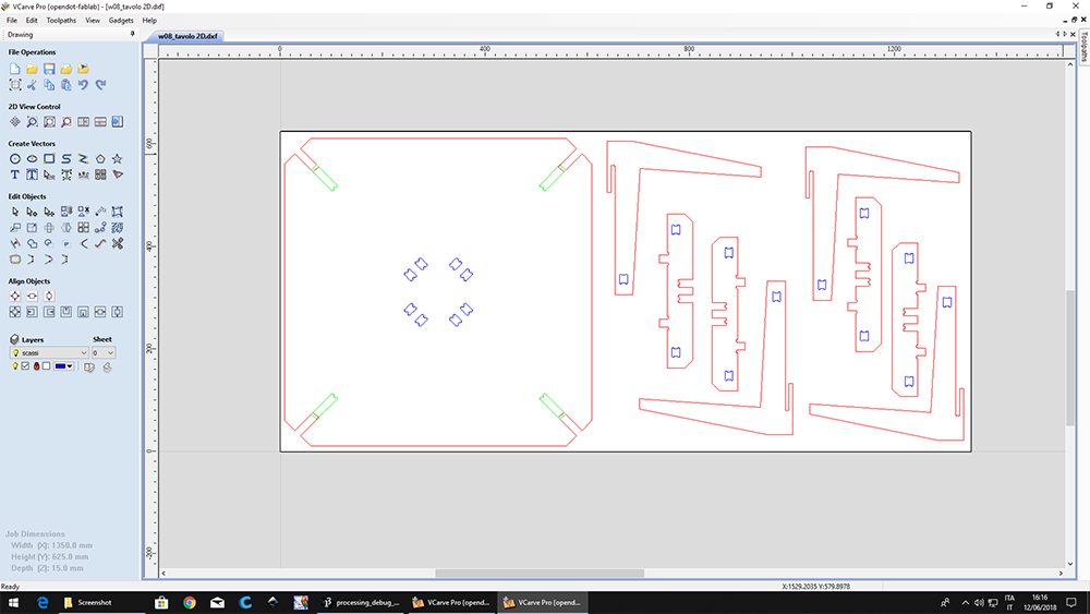
SET THE WORKINGS FOR THE HOLES
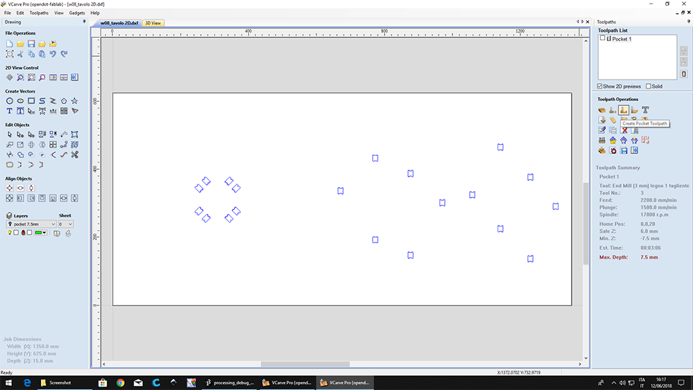
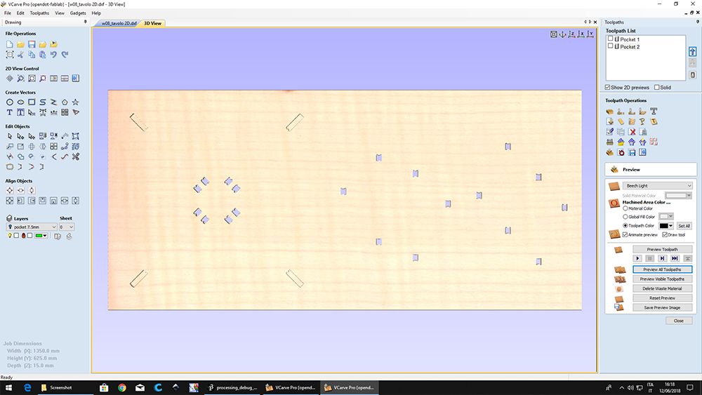
PREVIEW OF THE HOLES
SET THE WORKINGS FOR THE OUTLINES
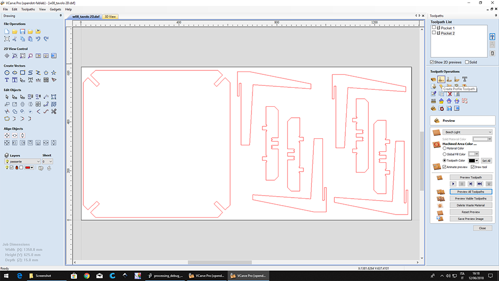
ADD TABS
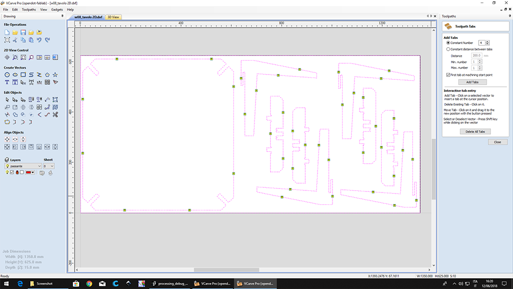
PREVIEW OF THE OUTLINES
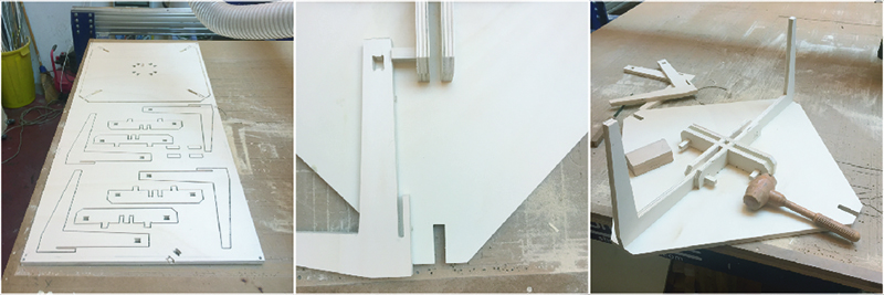
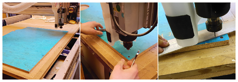
During my period of work in a furniture factory I had the possibility of using a 5 axis CNC machine (Biesse Rover C) where the zeroing of the axes was an automatic process and the panel was blocked by suction cups. At Opendot, on the other hand, we have a simpler CNC machine, where the processes to prepare the machine for work are longer.
• 1st Step •
Clean the worktop.
• 2nd Step •
Fix the panel using wood screws, positioning them roughly just outside the working area.
• 3rd Step •
Fit the chosen drill on the spindle making sure that the cutter is in a position to pass the panel, but not too much to avoid vibrations.
• 4th Step •
Set the X and Y axes manually by means of the software by moving the spindle in the bottom left corner, paying attention to the position of the screws.
• 5th Step •
Set the zero of the Z axis using an instrument composed of a metal plate, with a thickness known from the software, resting on the panel and a clamp attached to the motor. When the cutter touches the plate the circuit closes, finding the exact value of Z.
• 6th Step •
Turn on the suction system.
• 7th Step •
Move away from the maneuvering space of the CNC machine.
• 8th Step •
Start processing.
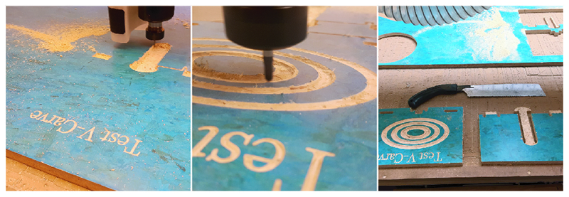
To test the CNC machine, we downloaded a model from the site flexiblestream.org. To make the test complete we added a writing and a curved geometry. In this way we have all types of workable geometries:
• 2D machining: includes that group of processes contained in a single file made at the same depth, which therefore have a constant "Z" value (such as occurs in the lasercut).
• 2.5D machining: files are very similar to those 2D but with the possibility to set up operations with different values of "Z".
• 3D machining: means that within individual processes may have varying values of "Z".
To make the 2D and 2.5D files we used Rhinoceros (with the above procedures). For 3D machining we used the Fusion 360 CAM. To create the file for 3D processing with Fusion 360 first made the surfaces with Rhinoceros. Export the .step file and import it into Fusion. The first thing to do is to set all the tool parameters that we will use for machining. It will be a 6mm diameter cutter and with the round head, called ball end mill.
 Close Project
GROUP PROJECT
Compare the performance and development workflows for other architectures
OpenDot Group Page
For this assignement I tried to know and to program one Teensy 3.2
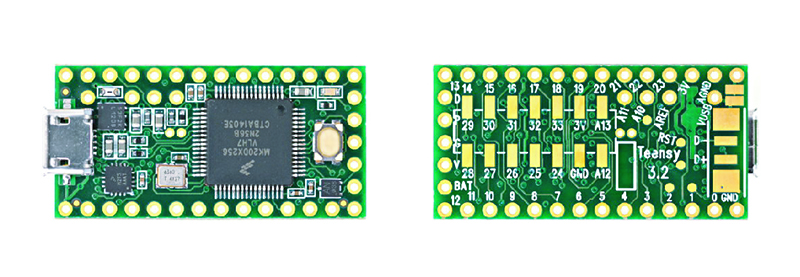
The Teensy is a complete USB-based microcontroller development system, in a very small footprint, capable of implementing many types of projects. All programming is done via the USB port. No special programmer is needed, only a standard micro USB cable and a PC or Macintosh with a USB port. This board can be easily programmed with the Arduino IDE, but it needs some simple steps and the installation of the dedicated software and the Arduino IDE plug-in. First of all we have to download Teensyduino, which is a software for running sketches on Teensy (the Arduino IDE must have already been installed) and follow the tutorial for the installation. The Teensyduino installer adds the necessary support files to Arduino. Select the location where you extracted the Arduino Software.
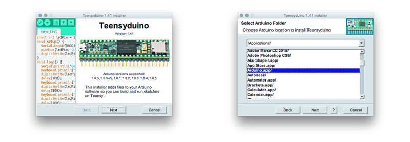
Teensyduino can automatically install many libraries that are tested and verified to work with Teensy. Usually it's best to allow the installer to add them all. The installer will copy all the necessary files into your Arduino Software, when you click the "Install" button.
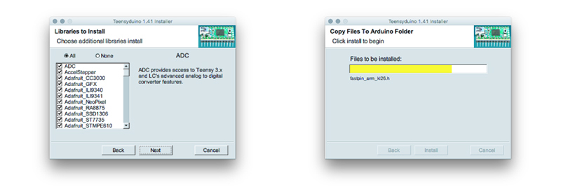
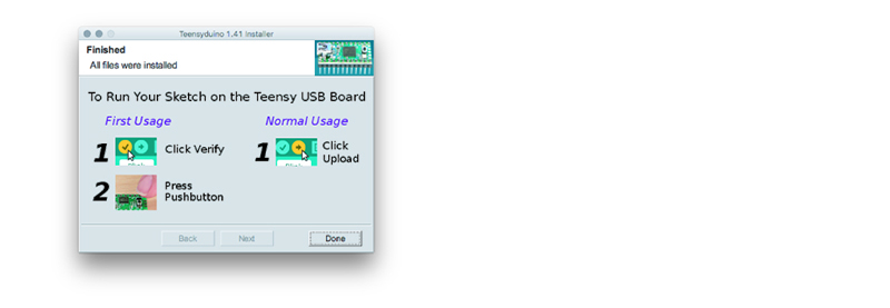
When installation is finished, you will see this final screen. Just click Done to quit the installer.
To be able to communicate the board with the IDD of arduino, you need to install Teensy Loader. It is run automatically when using Verify or Upload within the Arduino software.
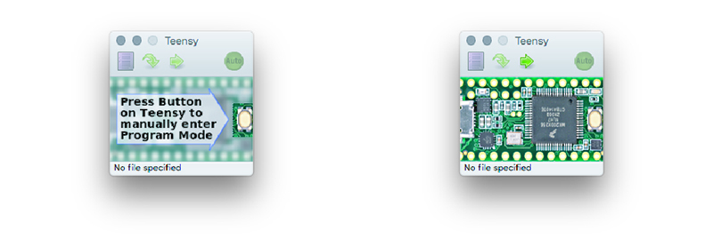
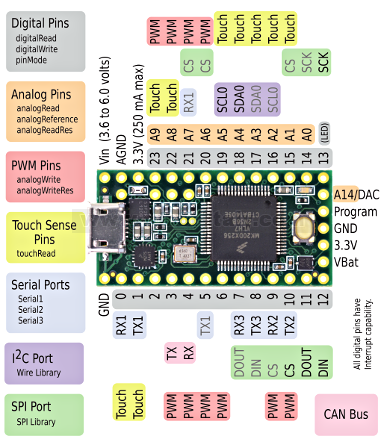
The Teensy Loader should appear as a small window. If the Teensy board is not connected, you should see this window on the left. If HalfKay is running, you should see the window on the right. If not, simply make sure your Teensy board is connected, and press the pushbutton to run HalfKay. The Teensy Loader will quickly recognize it. Now I can plan my Teensy like an Arduino always keeping in mind the location and name of the pin.
To have fun with the Teensy I used the breadboard, the LEDs and some components of the Arduino starter kit.
After finishing the teensyduino installation procedure, I can load the sketches using the Arduino IDE.
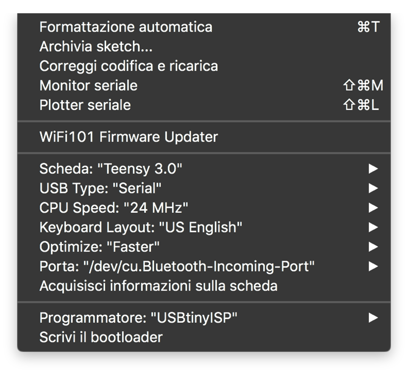
tools> tab> teensy 3.0 == to select which tab
tools> usb type> serial == to select how the data will be transmitted
tools> cpu speed> 24Hz == to set the clock speed
I am not able to program, so for my "HelloWorld" I relied on what had already been done and the manual of Arduino. I followed this tutorial by Michele Maffucci using his codes as a start (rewritten to become familiar), and then modifying them.
With this program I'm telling my Helloworld to keep the LED on and to turn it off if I hold the button down. The LED will light up as soon as the button is released. The starting program was this:

                #define LED 8
                #define BUTTON 7
                int val = 0;

                void setup() {

                pinMode (LED, OUTPUT);
                pinMode (BUTTON, INPUT);
                }

                void loop() {

                val = digitalRead (BUTTON);

                if (val == HIGH) {digitalWrite (LED, HIGH);
                }
                else {digitalWrite (LED, LOW);
                }
                }
I tried to change the code copied by Maffucci, and after several changes I came to this result. Initially, the LED lights up for one second (digitalWrite (LED, HIGH) delay (1000)) and is turned off for a quarter of a second (digitalWrite (LED, LOW) delay (250)). As soon as I press the button the LED starts blinking alternating 5 tenths of a second on and 5 tenths off ((digitalWrite (LED, HIGH) delay (50) - (digitalWrite (LED, LOW) delay (50)).
                #define LED 8
                #define BUTTON 7
                int val = 0;
                int old_val = 0;
                int stato = 0;

                void setup() {
                pinMode(LED, OUTPUT);
                pinMode(BUTTON, INPUT);
                }

                void loop() {
                val = digitalRead(BUTTON);

                if ((val == HIGH) && (old_val == LOW)){
                stato = 1 - stato;
                }

                old_val = val;

                if (stato == 1) {
                digitalWrite(LED, HIGH);
                delay(1000);
                digitalWrite(LED, LOW);
                delay(100);
                }
                else {
                digitalWrite(LED, HIGH);
                delay(50);
                digitalWrite(LED, LOW);
                delay(50);
                }
                }
When I pressed the button the first time, the LED did not immediately change the frequency of flashing. This is due to the fact that the program had to finish the cycle (IF), after which it was possible to start the second cycle (ELSE).
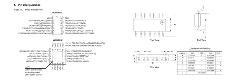
Another important part of the datasheet is the one where is the physical footprint and size of the component, which usually located at the end of all the documentation.
 Close Project
GROUP PROJECT
Review the safety data sheets for each of your molding and casting materials, then make and compare test casts with each of them
OpenDot Group Page
To try to create a mold, I tried to model something simple but which contained possible problems and technical difficulties. The piece that I decided to make is a head of lego divided into two and that was a candle holder. So in the model we have small vertical parts, spherical parts and very small male-female joints that fit together.
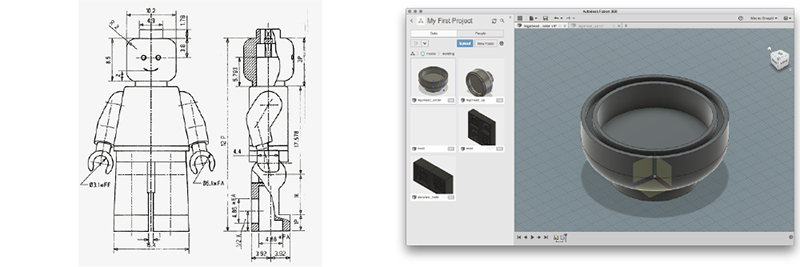
After downloading the technical drawings of a LEGO man and having reported the measurements on Fusion, I developed the 3D model. Initially I wanted to do everything about Fusion, but since I'm not a ninjia yet, I switched to Rhino to do the modeling part of the mold.
The main features that must have a mold are:
• DRAFT: vertical parts that will not be part of the final object must be slightly inclined to facilitate extraction.
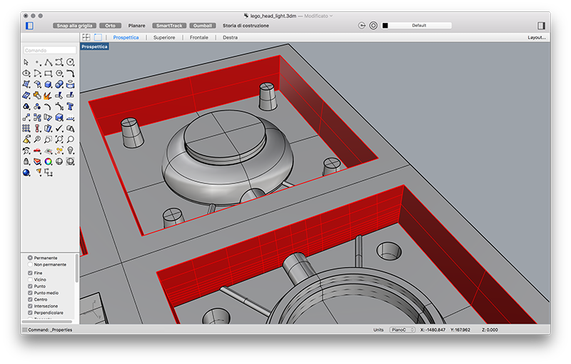
• UNDERCUT: there must not be any undercut work because it would be impossible both to work the mold and to extract the molded object.
• CONNECTIONS: can have any shape, must be male-female and are positioned on both parts of the mold. They are used to close the mold in the most correct way.
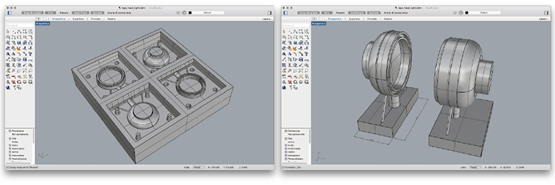
In the second attempt I used pyramid-shaped logos with a hexagonal section because the surfaces are always more than 90 ° so it is easier to mill these parts without having to make fillets.
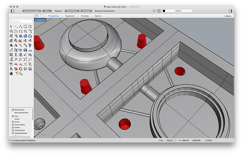
• CHANNELS: there must be more than one. A larger one where the material for making the molded object is cast, and one or two smaller to let the air out.
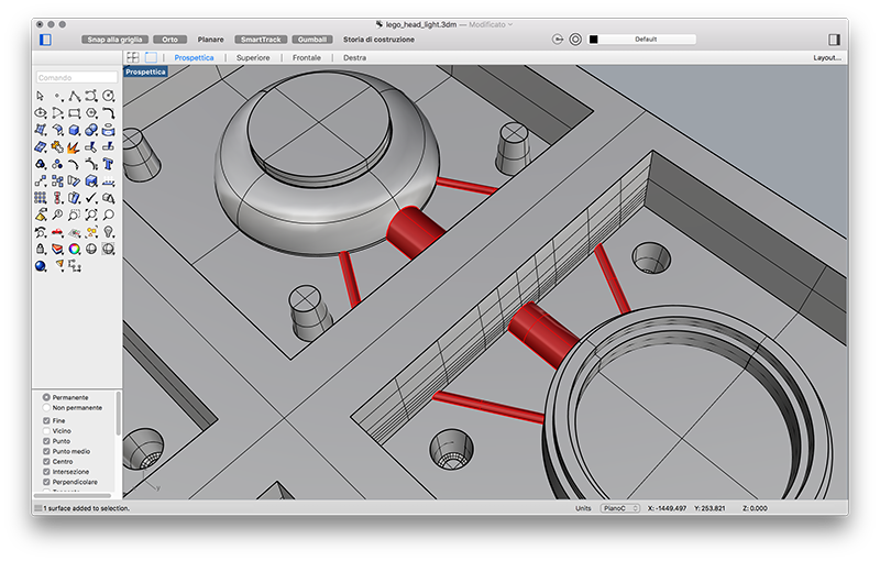
• CHAMFERS: the joints that are not part of the object must be shaped keeping in mind the characteristics of the tool that will be used to shape the mold. So to avoid problems with interlocking it is advisable to smooth all the edges.
Once the mold has been molded, the machining can be assigned using the Fusion 360 CAM. As a first step you must enter the characteristics of the drills that will be used for processing. In my case we have included:
• ø6mm double-edged cutter with round head
• ø4mm double-headed cutter with round head
• ø1.5mm milling cutter with two round head cutting edges
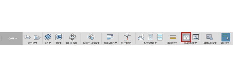
To enter the drill parameters, click on the manage> tool library menu. A window opens where you can create your own library, both locally and on the network. from here just click on the icon at the top right to access the parameter window.
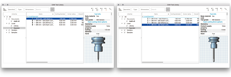
It is very important to set the parameters of the drills to the best and choose the right tool holder to be able to have a simulation of the workings more similar to reality, especially if you want to do very precise jobs.The Fusion tool library is very well done and is quite intuitive, so it is very simple for many parameters to understand what they refer to. Just get a gauge, measure the drill and enter the parameters. But we need some precautions:
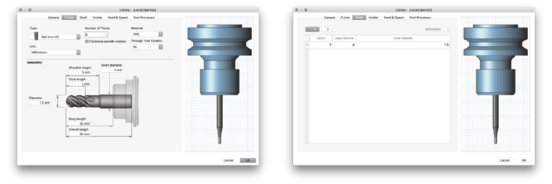
• Flute Length: indicates the length of the cutting part of the cutter. it is always better to insert a measure slightly less than that which is measured on the cutter to avoid the risk of ruining it.
• Body Length: indicates the part of the cutter that remains outside the instrument holder. Since the drills are hand-mounted on the spindle, an approximate measurement can be made depending on the length of the drill. A long drill would be better to let her in more to avoid the vibrations (for example on the ø6mm Overall Length = 100mm - Body Length = 60mm), while for a shorter cutter you can get in less (ø1.5mm Overall Length = 50mm - Body Length = 35mm).
Another interesting parameter is the Shaft, where one can act on the geometry of the cutter. The ø1.5mm drill has a stem with a diameter of 4mm which gradually tightens up to 1.5mm. In this Tab you can enter the dimensions of the upper diameter, the lower diameter and the distance between the two diameters.
For machining the mold I used three different types of 3D machining.
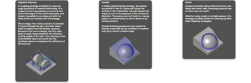
• Adaptive Clearing: performs roughing, works by levels falling from a given measure. Eliminate most of the unnecessary material. Usually, from 0.5 to 1 mm of material is left, depending on the material, in order not to risk marking the finished mold.
• Parallel: perform parallel finishing passes a short distance from one another. In this case I used a 4mm diameter cutter at the end of the round and I left between 0.5mm for a better finish.
• Pencil: it is the last step. A very small cutter is used (in my case ø1.5mm). This type of processing is convenient because it works only the edges that you want to finish, giving the possibility of obtaining of working with almost sharp edges.
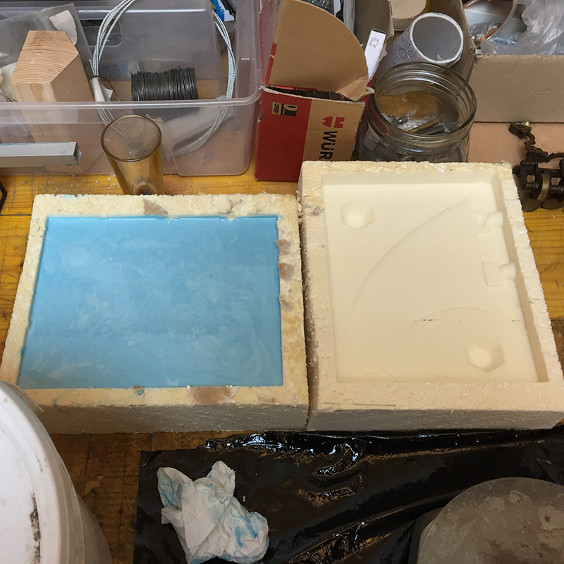
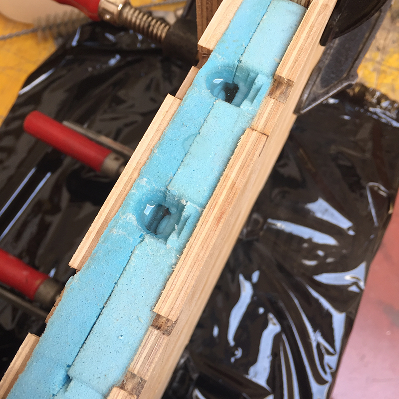
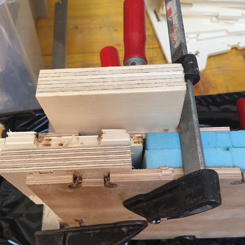
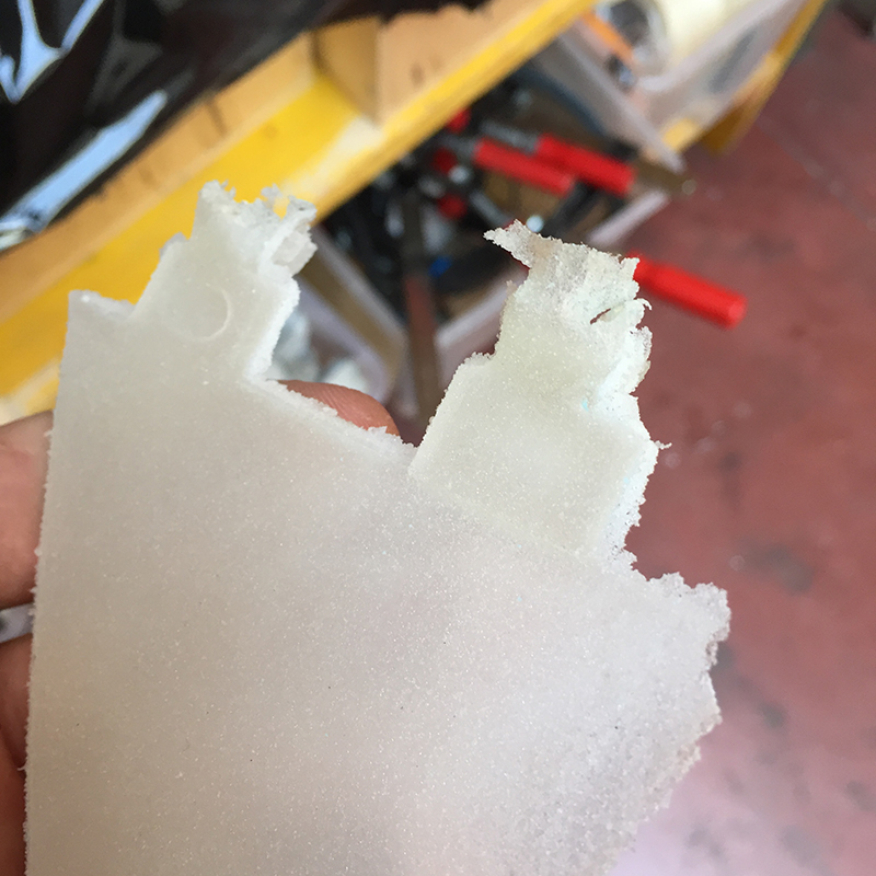
I have used an expanded foam used for thermal insulation which is easy to work but has many defects such as air bubbles inside which are not visible at the beginning of work. The first mistake made was to create walls that were too fine for this type of material. I also tried to recover using stucco, but I only made things worse.
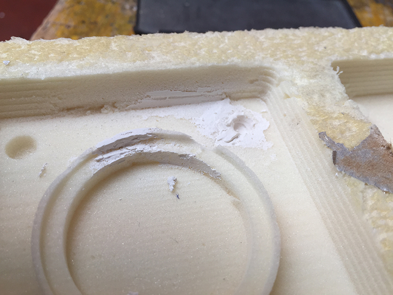
The foam is not a suitable material to make precision work. It could be used to make molds for objects without too much detail or with elements that are too thin. For precision work it would be advisable to use more compact materials such as wax or plastic materials.
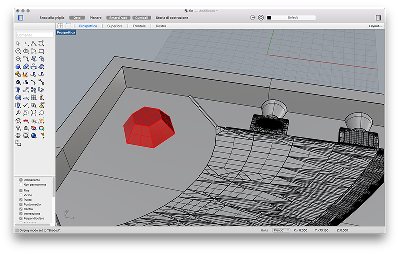
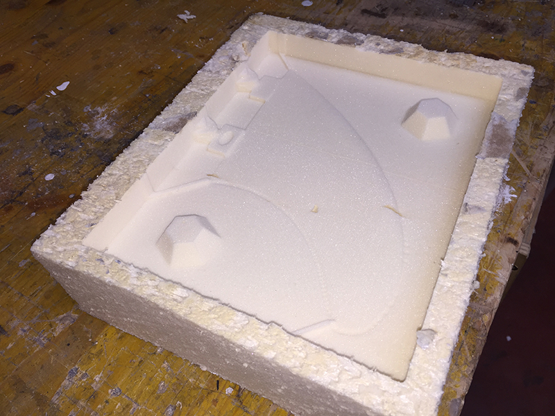
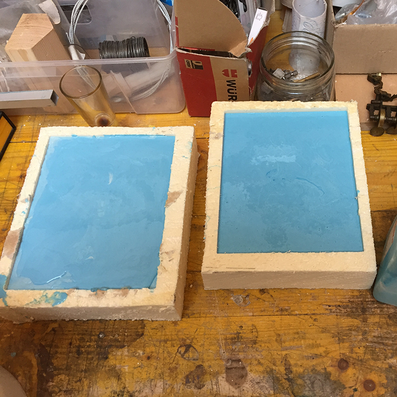
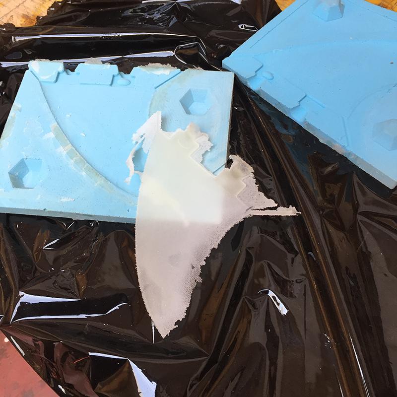
To create the mold we use a bicomponent silicone which when solidifies but remains rubbery. Trying to create a mold that worked, I tried with a fin for surfboards. Although very simple as an object and having very large surfaces, it has the characteristic of being fine. With the silicone mold, therefore, you have to be very careful because pouring the gypsum you risk that the plaster presses on the walls of the mold modifying its final shape.
For the second attempt I modeled a surf fin. the part of CAM has been simpler because it has wider and more flat surfaces.
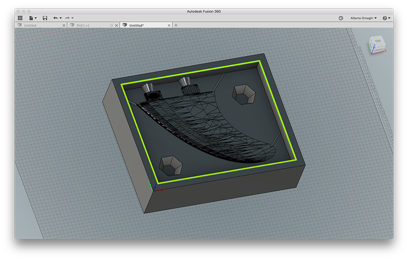
I used the same processes, with the only difference that instead of PENCIL processing I used a 2D POCKET. After the roughing part I was able to better define the model and at the same time to clean and flatten the flat parts in an effective and fast way.
To create the mold we use a bicomponent silicone which when solidifies but remains rubbery. Trying to create a mold that worked, I tried with a fin for surfboards. Although very simple as an object and having very large surfaces, it has the characteristic of being fine. With the silicone mold, therefore, you have to be very careful because pouring the gypsum you risk that the plaster presses on the walls of the mold modifying its final shape.
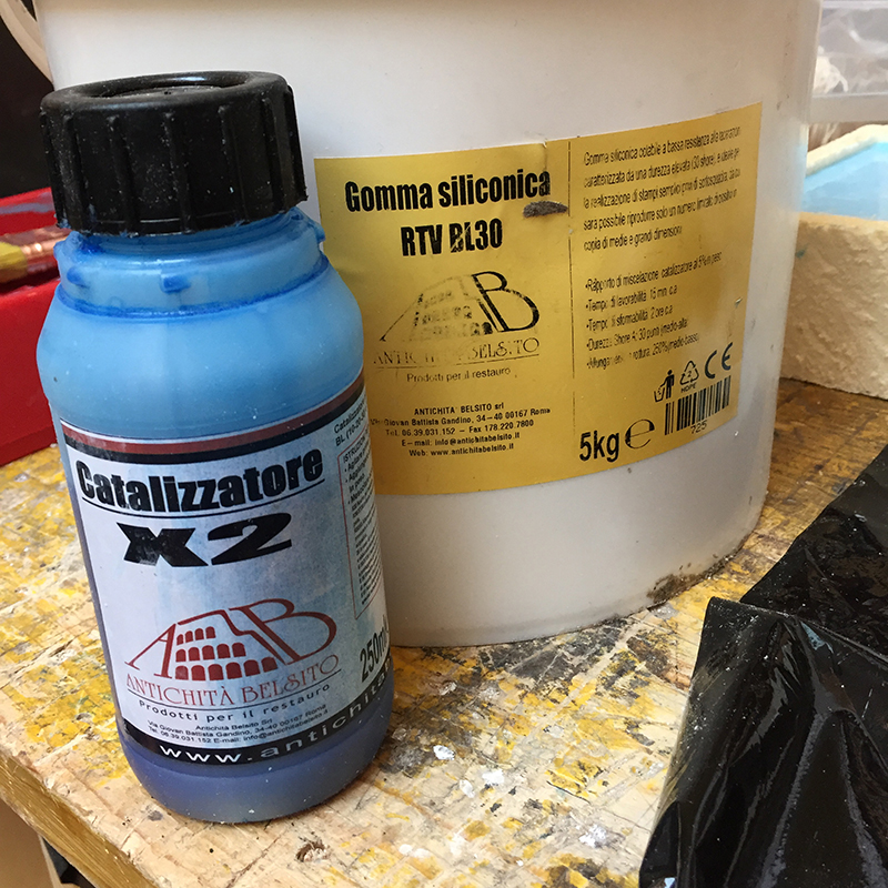
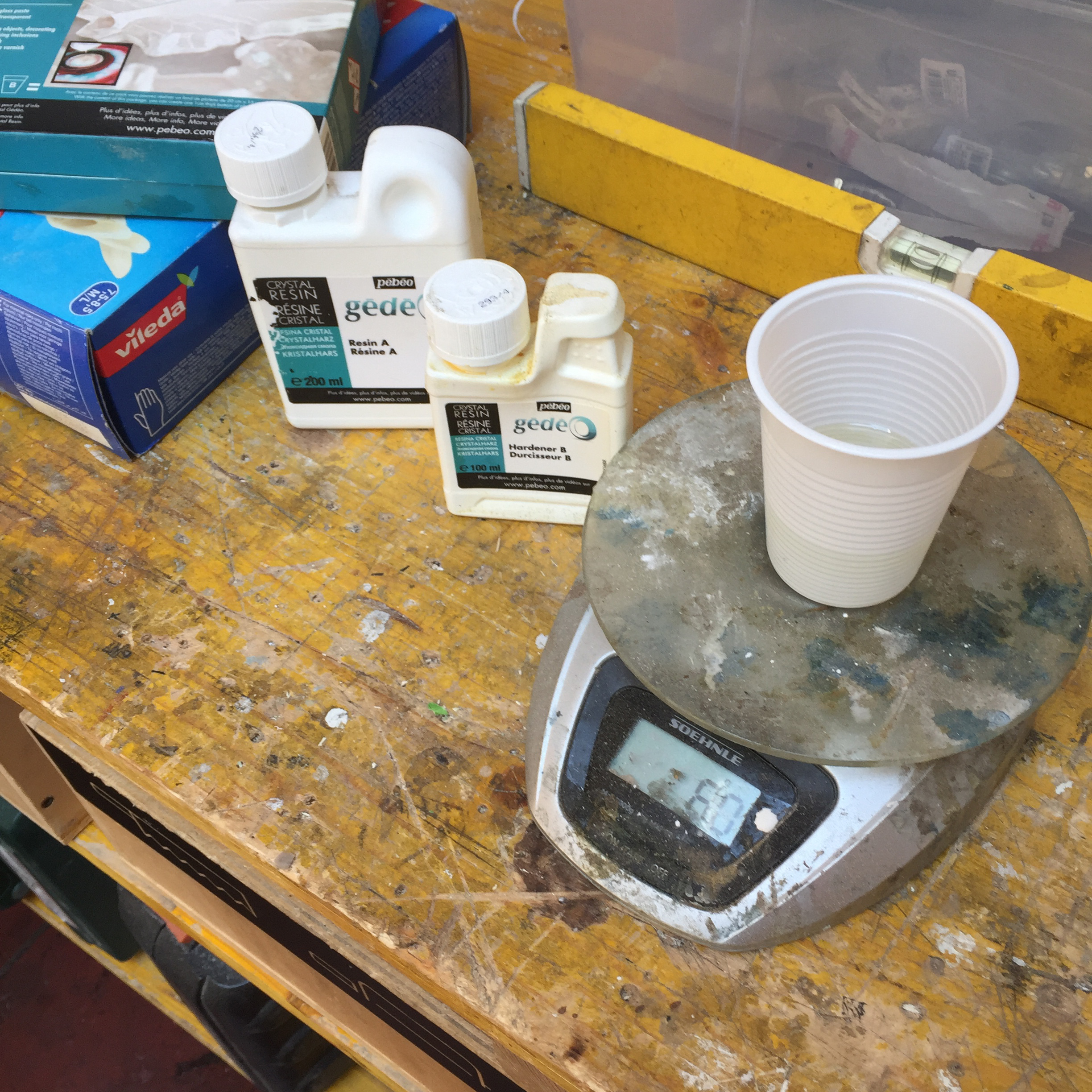
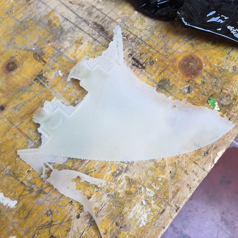
Since nothing was successful, I decided to experiment with the catalysing of two-component silicone. I prepared the silicone for the two parts of the mold at two different times using slightly different percentages. In one I used exactly 5% of catalyst, while in the second I put 5 grams more.
In theory, for such small quantities it should change little. The mold with the upper catalyst concentration should harden before.
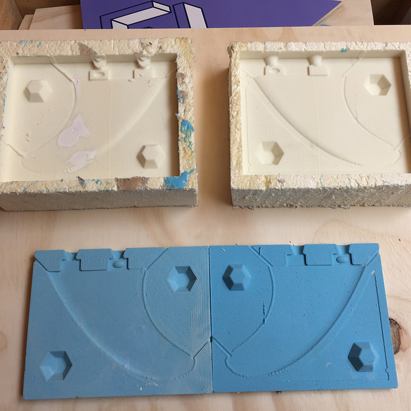
• the hexagonal section markers were very functional both as modeling and as a final result.
• With foam and silicone it is advisable to make molds for models with simple shapes and not too thin.
• It is always necessary to make an accurate choice of materials according to the object you want to achieve: dimensions, details, thicknesses, finish and final result. it is always a mix of material used to make the mold of the mold, material of the mold and material of the final object.
You can do (almost) anything
 Close Project
GROUP PROJECT
Measure the analog levels and digital signals in an input device
OpenDot Group Page
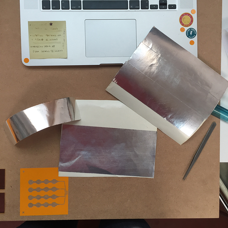
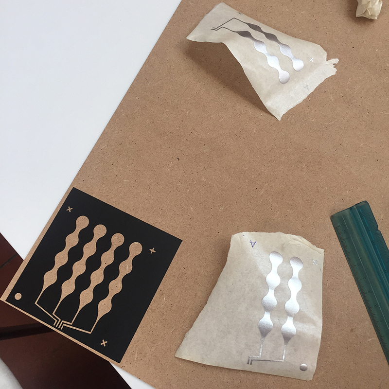
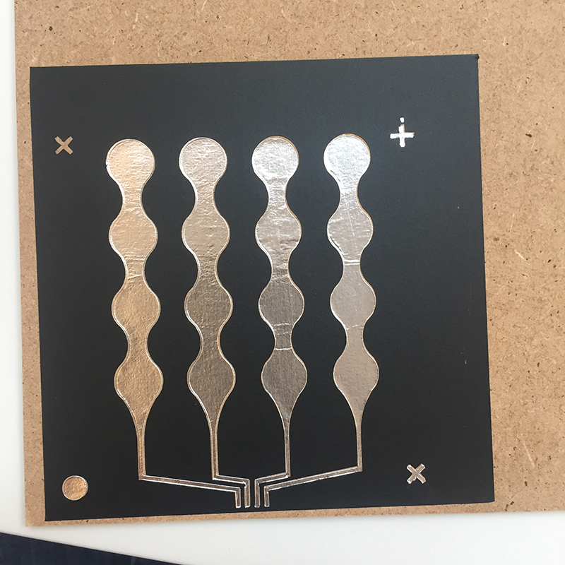
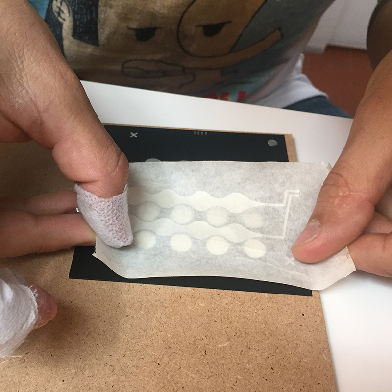
I chose as input device to develop a trackpad according to the final project. I would like to use it as to control the table and move in a certain direction for a certain period. I started by drawing on Matt Blackshaw's project by creating a grid with aluminum tape. I made the pad on an MDF support. First I cut the aluminum tape getting 8 strips (4 for the abscissas and 4 for the ordinates) and then I cut the vinyl and used it as a mask to place the aluminum strips, and as an insulator between the two layers. In order to make the connections, I used sewing pins. The layers are:
• vinyl - mask to place the first layer of aluminum
• aluminium - first layer (X)
• vinyl - layer to separate the first from the second layer of aluminum
• aluminium - second layer (Y)
• vinyl - final layer
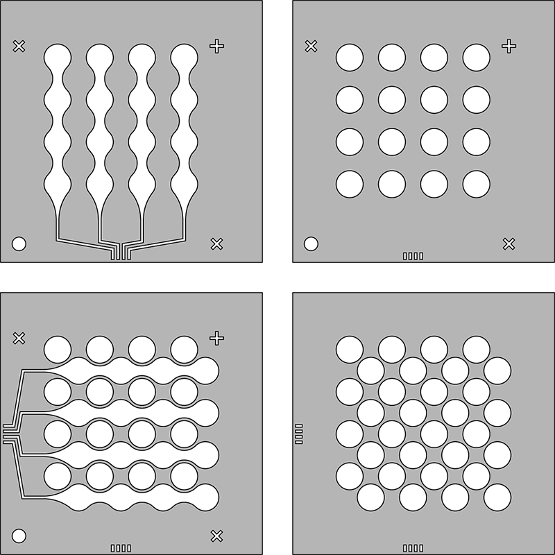
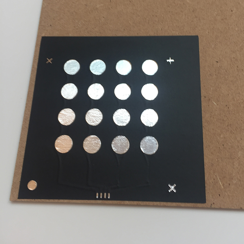
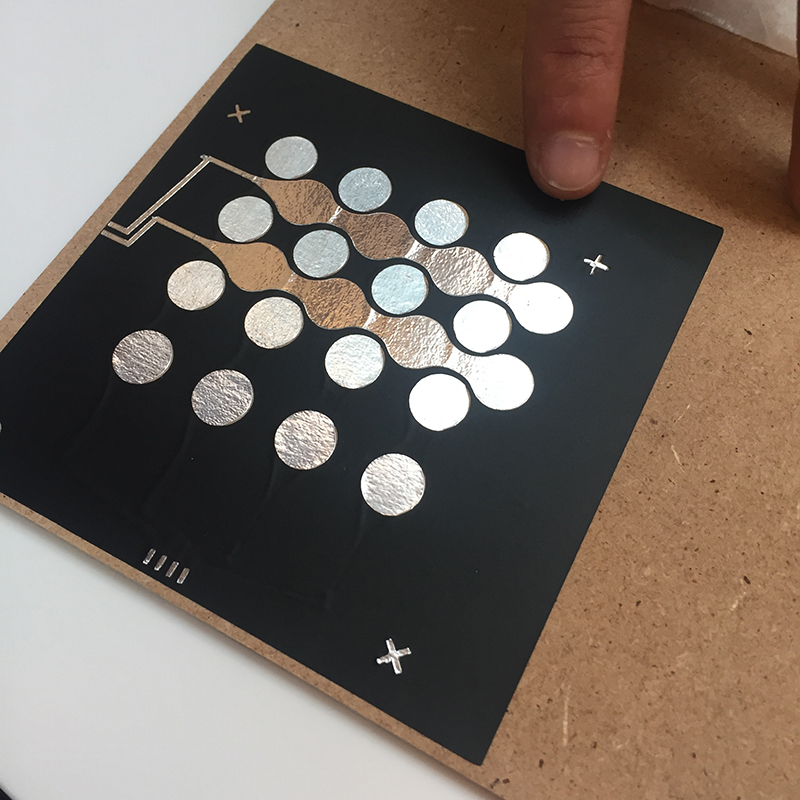
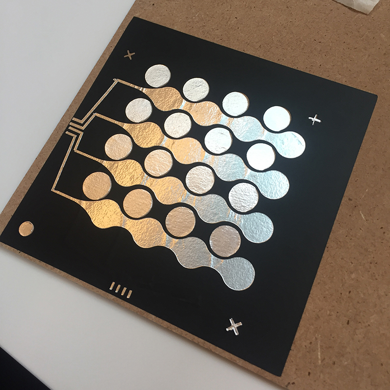
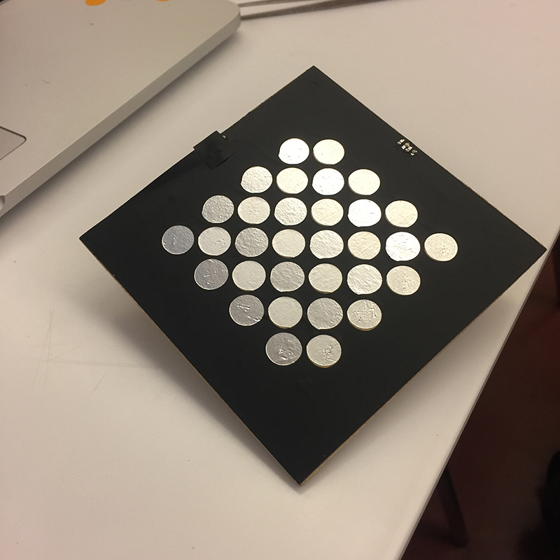
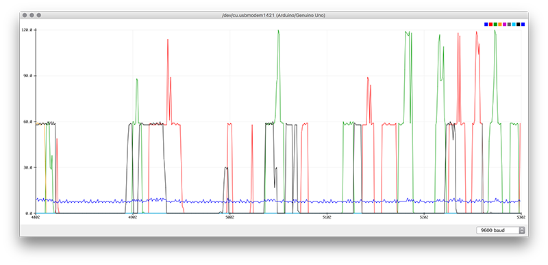
The grid has been crossed in this way to make it possible to read the position of the finger. Mine is not as effective as that of Matt Blackshaw because it leaves too many gaps between one pad and another. I know it would be wrong to document the work done with Arduino, but I would need to do other tests to test which resistors (which regulate sensitivity) work best matched with which capacitors (which clean the signal).
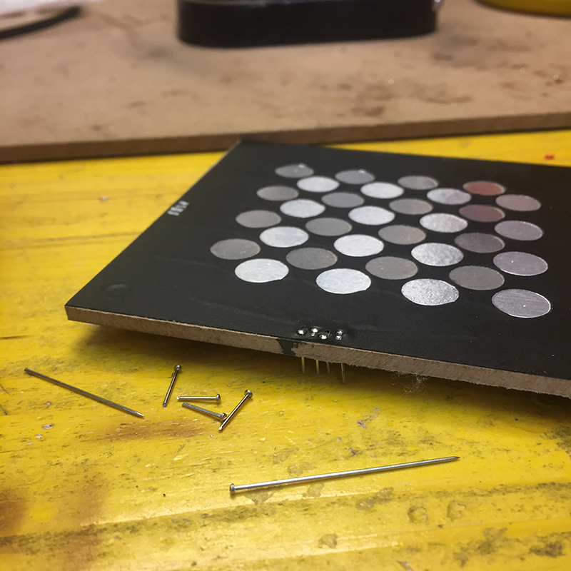
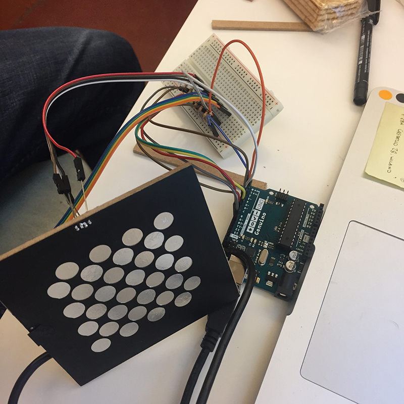
I connected each aluminum track to an Arduino pin to receive the signal. Instead the signal is sent by a single pin for all the tracks. In this case I used 10kΩ resistors for each track. So I downloaded and installed the library with a sketch of capacitive sensors. I modified it slightly to simplify the reading and any future changes.
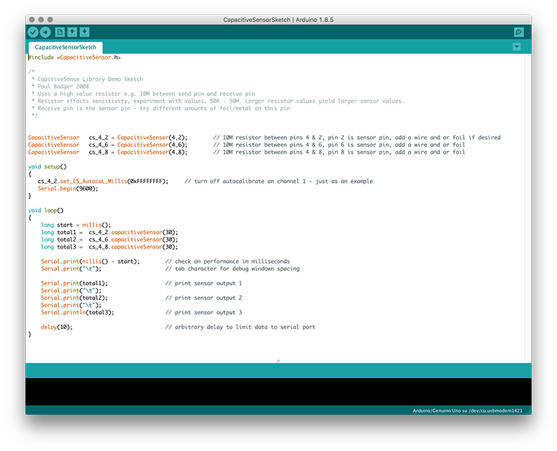
• #define send_pin 2 = I have declared that the pin that sends the signal is 2
• capacitiveSensor csx [4] = I have declared how many and which are the pins that send and receive the signal
• for (int i, ...) = I have declared to do 4 sequential cycles
• Serial.print("\n") = I said to display 8 values per line on the serial monitor
...and this is the result
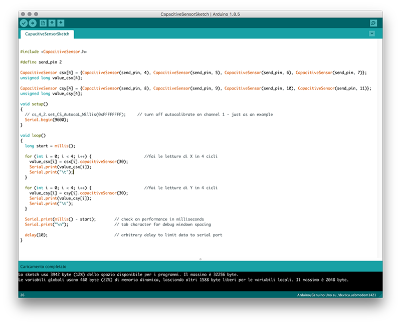
                #include

#define send_pin 2

CapacitiveSensor csx[4] = {CapacitiveSensor(send_pin, 4), CapacitiveSensor(send_pin, 5), CapacitiveSensor(send_pin, 6), CapacitiveSensor(send_pin, 7)};
unsigned long value_csx[4];

CapacitiveSensor csy[4] = {CapacitiveSensor(send_pin, 8), CapacitiveSensor(send_pin, 9), CapacitiveSensor(send_pin, 10), CapacitiveSensor(send_pin, 11)};
unsigned long value_csy[4];

void setup()
{
  // cs_4_2.set_CS_AutocaL_Millis(0xFFFFFFFF);     // turn off autocalibrate on channel 1 - just as an example
  Serial.begin(9600);
}

void loop()
{
  long start = millis();

  for (int i = 0; i < 4; i++) {                       //fai le letture di X in 4 cicli
    value_csx[i] = csx[i].capacitiveSensor(30);
    Serial.print(value_csx[i]);
    Serial.print("\t");
  }

  for (int i = 0; i < 4; i++) {                       //fai le letture di Y in 4 cicli
    value_csy[i] = csy[i].capacitiveSensor(30);
    Serial.print(value_csy[i]);
    Serial.print("\t");
  }

  Serial.print(millis() - start);        // check on performance in milliseconds
  Serial.print("\n");                    // tab character for debug windown spacing

  delay(500);                             // arbitrary delay to limit data to serial port
}
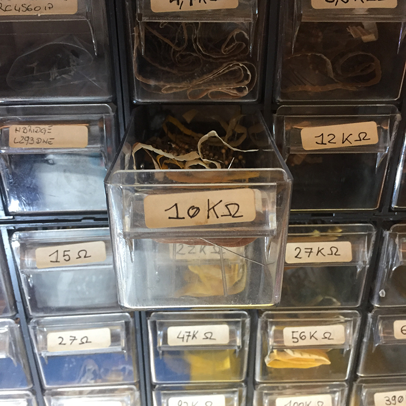
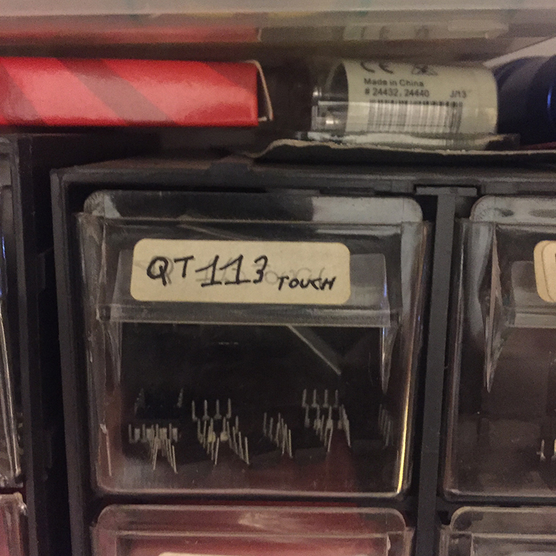
Continuing with the development of capacitive components, I tested the QT133 a touch sensor capable of detect near-proximity or touch. This last parameter is adjusted with the resistors. Raising the resistance value raises the sensitivity of the plate, so (in the case of my test) you can turn off the LED without touching the plate. I tried for example with two resistors: with a resistance of 470Ω I had to touch the plate to turn off the LED, instead changing it with a 4.7kΩ was enough to approach about 1cm to turn off the LED. Another important step for the proper operation of the QT113 is the choice of the capacitor. In this configuration I used one of 10 nf. The capacitor is useful for stabilizing the signal. A capacitor with a high value flattens the signal and does not allow interaction between the chip and the touchpad, while one with a lower value makes it more disturbed (in addition to burning all the LEDs - I have burned 5).
The next step will be to combine the two tests I did starting from connecting eight QT113s to the touchpad board. Then I have to find the code to be able to trace the movement of the finger and translate it into a vector that will give the coordinates to the engines that will move the table.
I do not think it will be very simple ...
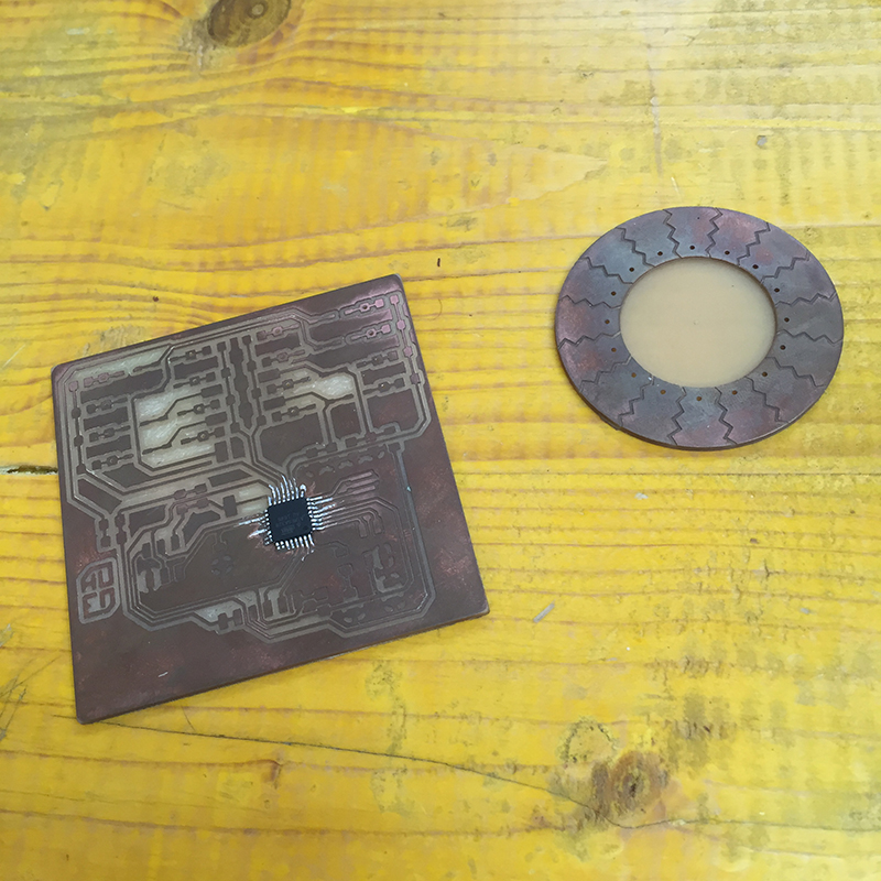
This is the first test of a multitouch ... but it did not go well ...
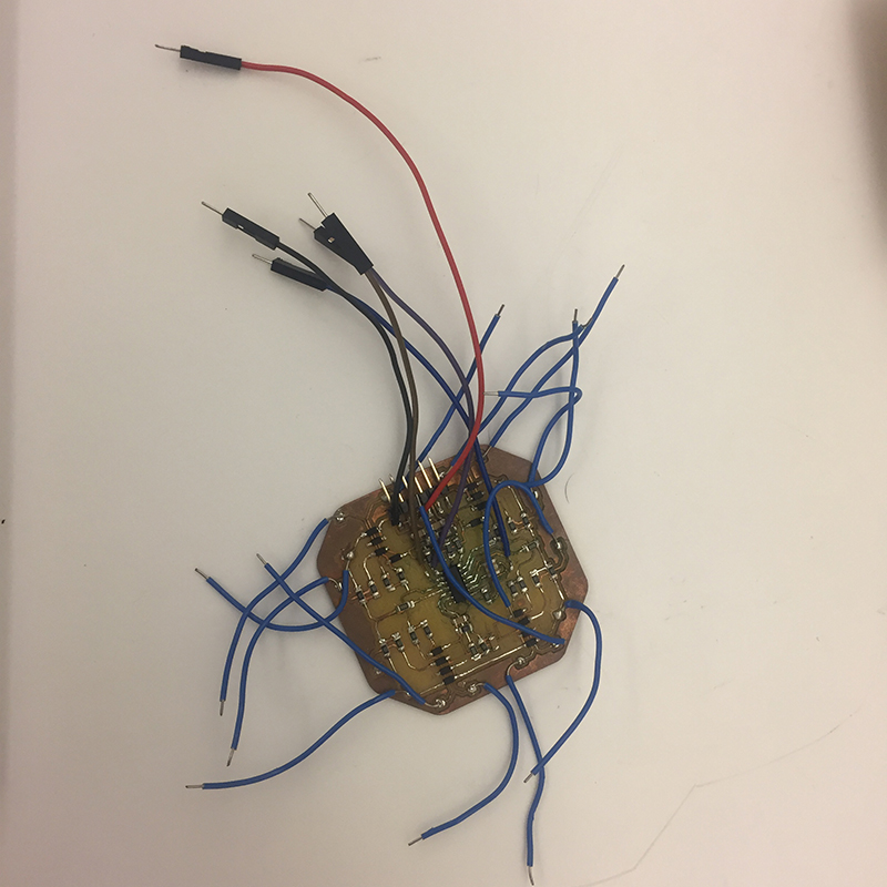
Even for the multitouch for the final project it did not go very well.
Unfortunately I did not succeed in the scheduled time to finish it and to program it, but certainly in the coming weeks I would make it work.
Compared to the previous version I replaced the ATtiny 44 with an ATMega328, I added an ISP connector and I re-ordered all the components.
Finally, the element that will read the position of the finger is a ring composed of 16 keys that can return 32 values to tell the table in which direction to go. I say 32 because I would like the controller to read also the position of the finger touching two keys.
 Close Project
GROUP PROJECT
Measure the power consumption of an output device
OpenDot Group Page
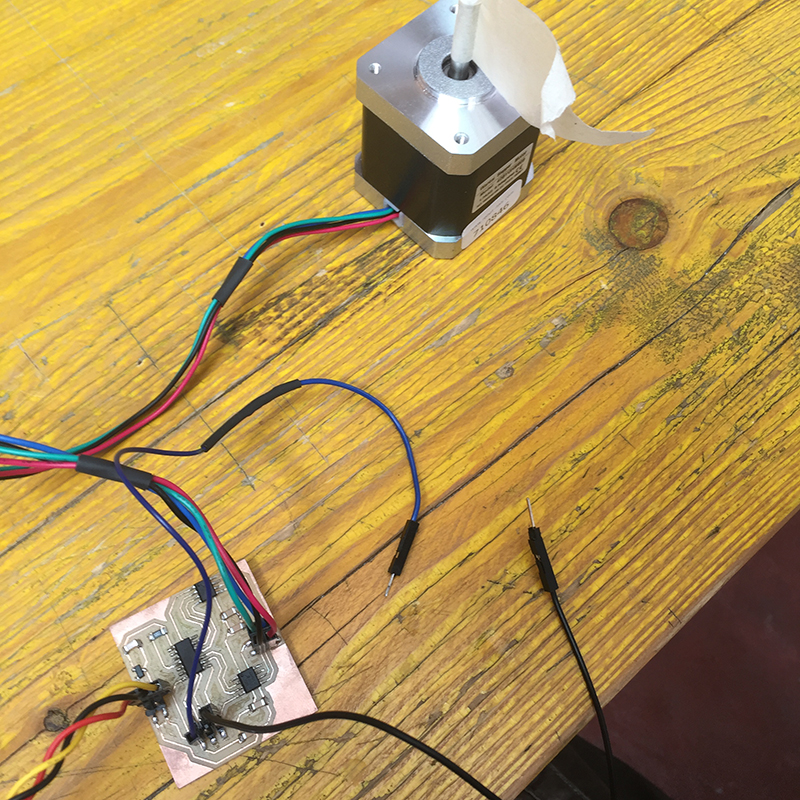
As an output device I decided to test the stepper motors, also depending on the fact that I would also like to use them for the final project.
I started from the files provided by Neil during the lesson with the intent to modify them for my purpose. First of all I took the same components and I redid the board.
Since I want to attach wheels to stepper motors, I need the motor to move continuously until it receives an input and changes direction of rotation. Input is given via a button.
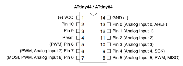
After consulting the datasheet of the ATtiny44 I set up the MOSI pinout (PA5) as a digital input and I enabled the internal pullup, connecting in this way to the ISP connector of my board.
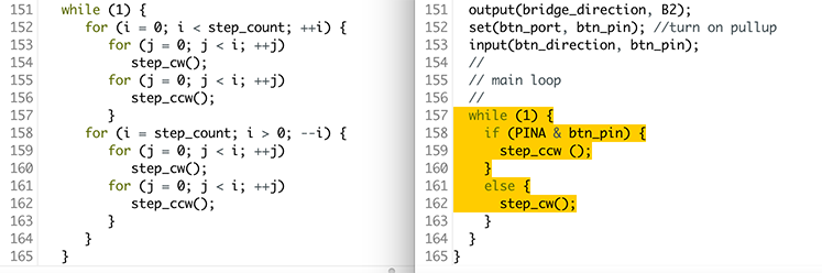
To use the button I added three #define to the Neil code, stating which port and what microcontroller pin is connected to.
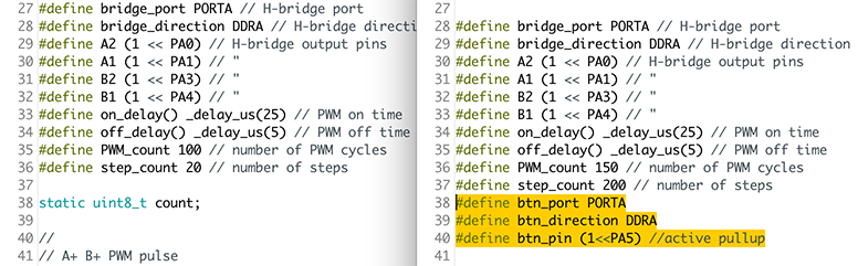
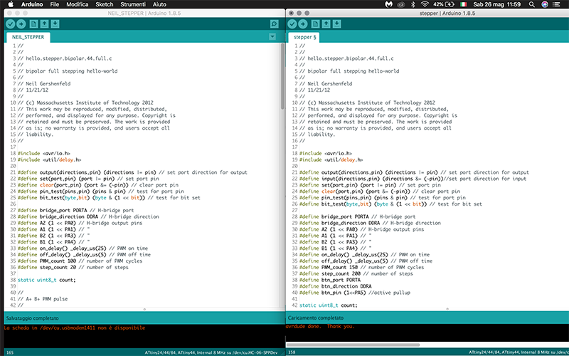
Then, in the "main loop" I declared that actions should have done the stepper motor according to the state of the button.
If pressed the engine runs counterclockwise, while if the button is not pressed, the motor turns clockwise.
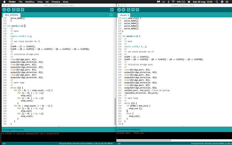
As soon as I loaded the Neil code on my card the stepper motor did not move but I felt it was giving impulses. After checking the microcontroller datasheets, the driver and the engine, and after verifying that all connections were correct, I realized that I had set the internal clock at 1 MHz instead of setting it to 8 MHz.
By changing the internal clock to 8 MHz it started spinning perfectly.
For the final project instead of using the two microcontrollers A4953 for each motor, I preferred to use the POLOLU DRV8825 drivers, as the range of modifications that can be made on the motor is wider, as the resolution of the microstepping that can go from 1/6 at 1/32. Also with the drivers I can occupy less pins on the ATMEGA328.
Here the link to the final project stepper motor implementation.
Creating an interface means putting in communication / creating a connection between two devices, physical or virtual.
In our case we will put in communication / interface a virtual application with a physical device.
The virtual interface will be created with Processing.
Processing is a programming language that allows you to develop various applications such as games, animations, interactive content and generative works of art.
It inherits all the syntax, the commands and the object oriented programming paradigm from the Java language but also offers numerous high-level functions to easily manage the graphic and multimedia aspects.
In the simplest of cases you can create programs to turn on or off an LED and regulate its intensity.
In my case I would like to create an interface to control the table that will be my final project that will be equipped with stepper motors.
The interface that will be created will then have to check the speed of the engines and the position that the table will have to take.
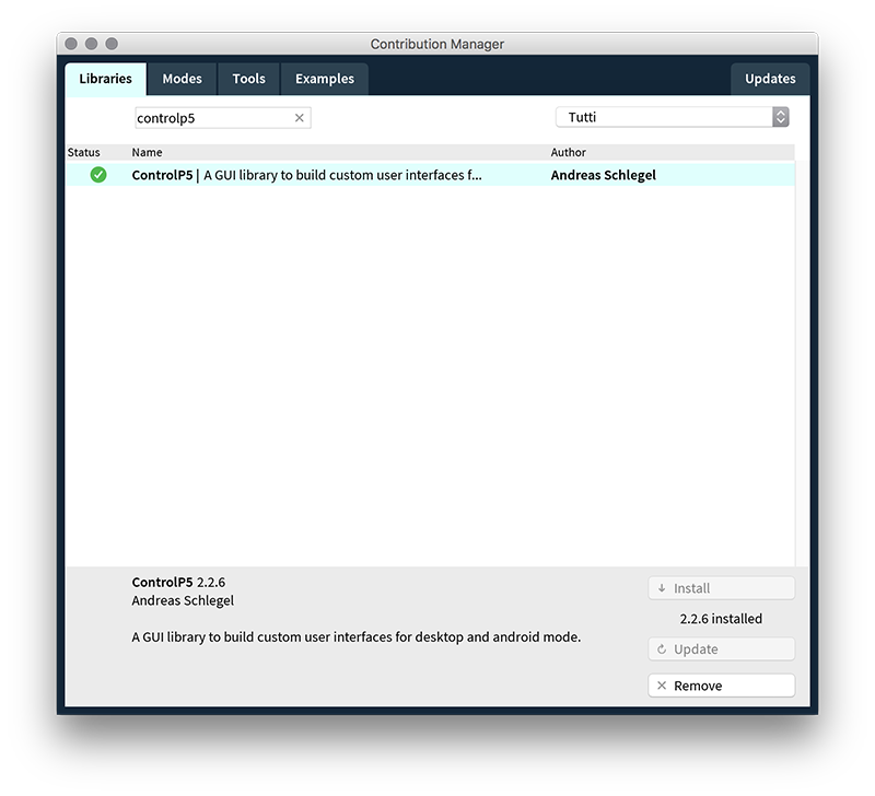
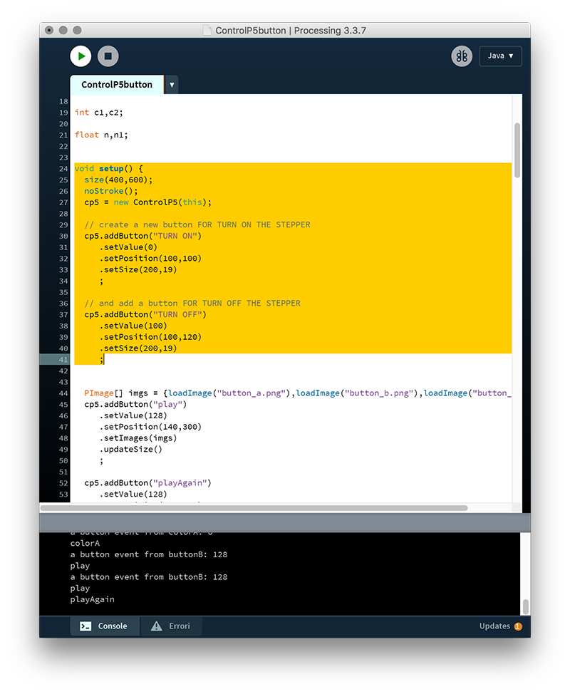
I started by downloading the "ControlP5" library. This library contains a series of sliders, buttons and various controllers. Depending on the need, all these examples can be edited and merged into the same interface.
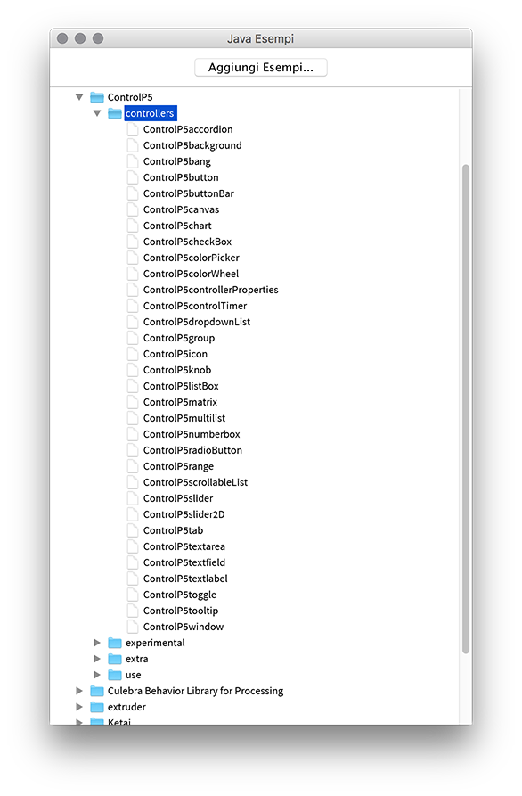
I decided to start with the example "ControlP5Button". Of the three buttons that have been designed I need one to turn on and one to turn off the engine.
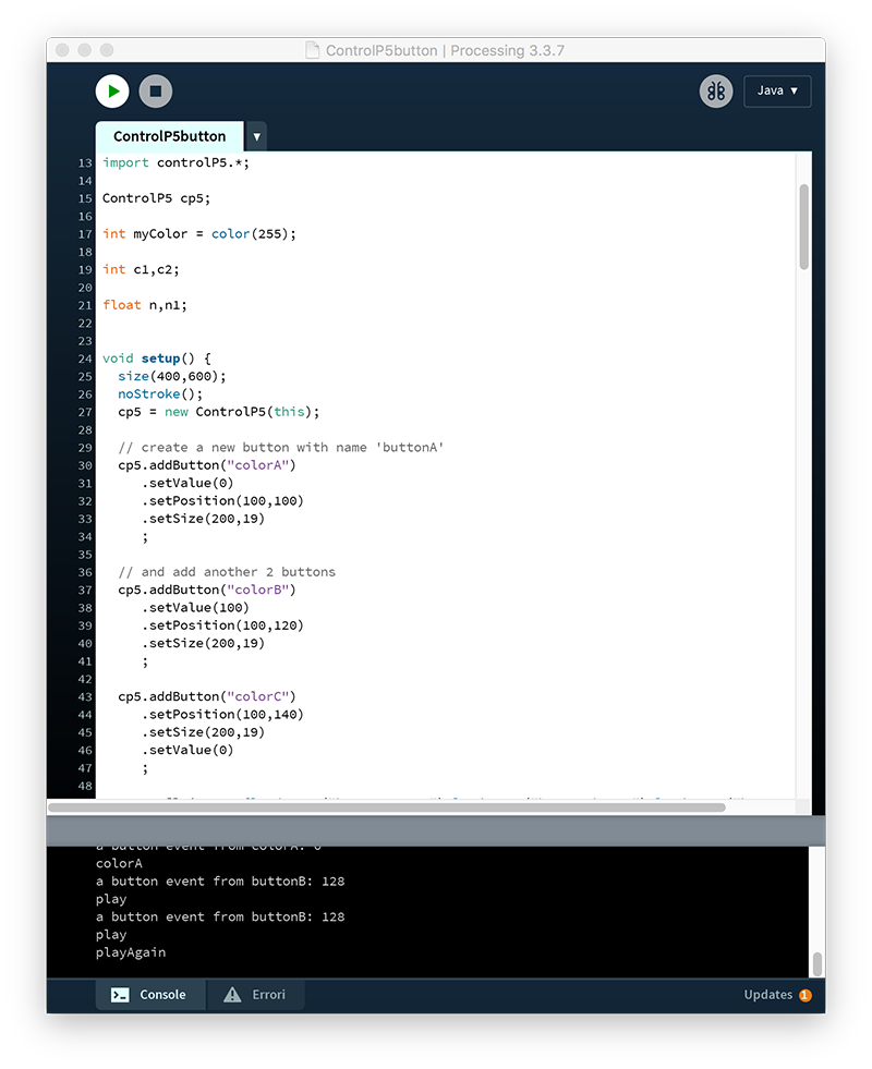
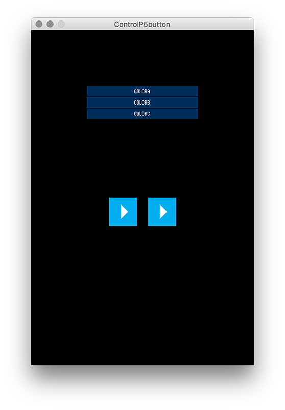
I decided to start with the example "ControlP5Button". Of the three buttons that have been designed I need one to turn on and one to turn off the engine.

Since I could not finish this assignment right away, and in the meantime we started to decide what would have been the project we would have developed for the two weeks of machine design, instead of creating an interface to access or switch off a stepper motor, I realized the 'more complete interface to control the movements of the robot-basket.
The interface documentation can be found on the machine design page.
GROUP PROJECT
Send a message between two projects
OpenDot Group Page
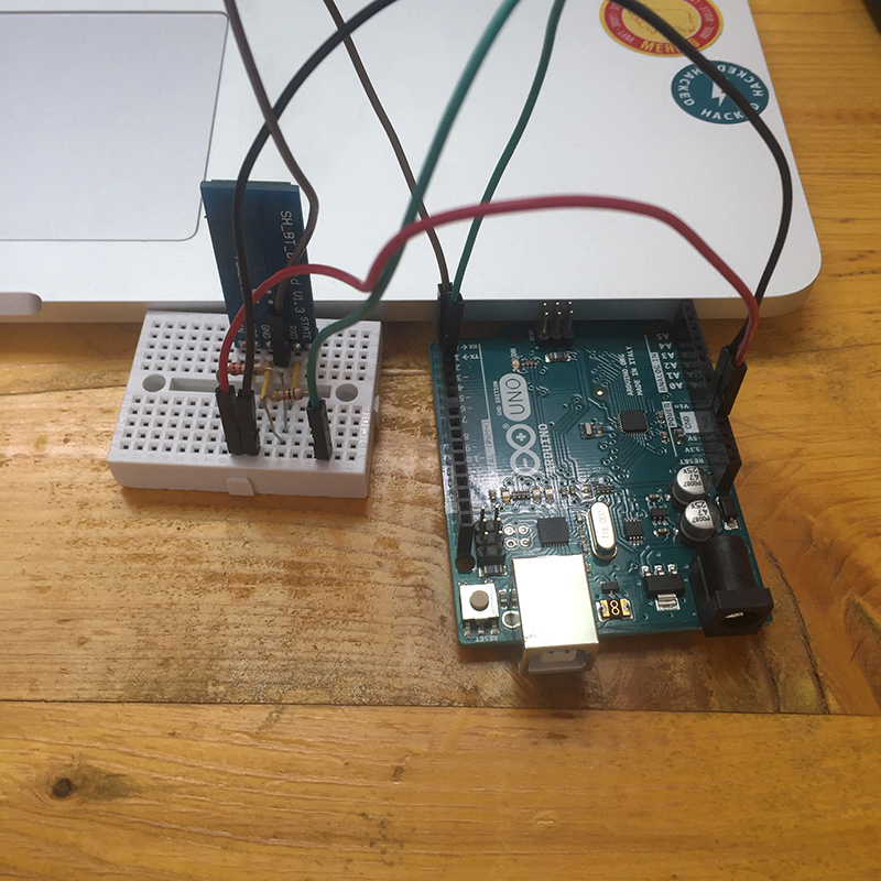
For my final project I would like to control a robotized table using a multitouch controller. the two devices, the table and the remote control communicate with each other via bluetooth.
Bluetooth (often abbreviated as BT) is a technical-industrial data transmission standard for wireless personal networks. The biggest advantage that bluetooth communication has is that it allows to associate different devices with each other.
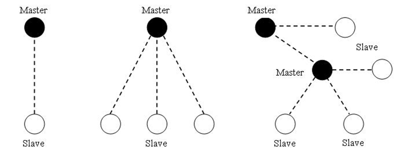
The devices that communicate with this system can be associated in different ways, but in every type of association between devices there is always a "master" and one or more "slaves".
Being a master means "asking questions and receiving answers". For example, in a weather station there may be a series of sensors for controlling temperature, humidity and pressure. There will be a microcontroller (master) that will continue to ask each sensor (slave) for information.
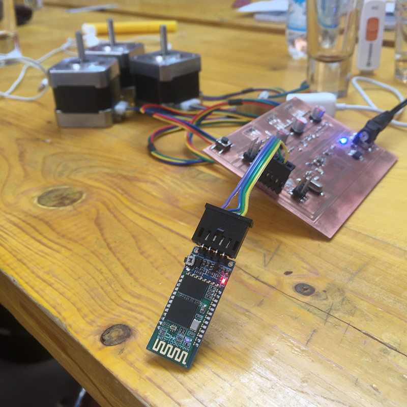
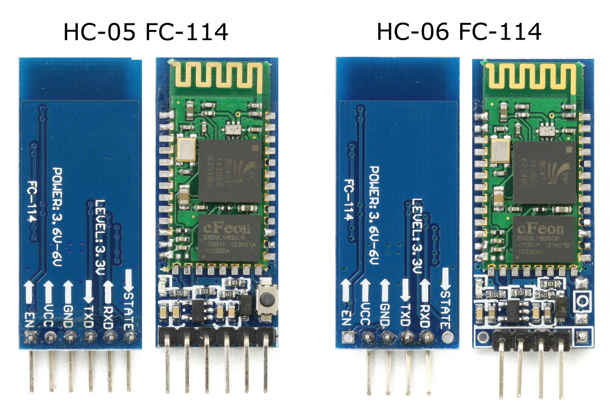
For my final project I will go to use two bluetooth modules, one that will work as a master and one as a slave. The module that will work as master will be the HC-05, while the slave will be the HC-06.
The difference between the two modules is that HC-05 is a more capable module that can be set to be either master or slave, but HC-06 can only be slave. The module has two modes of operation, Command Mode where we can send AT commands to it and Data Mode where it transmits and receives data to another bluetooth module.
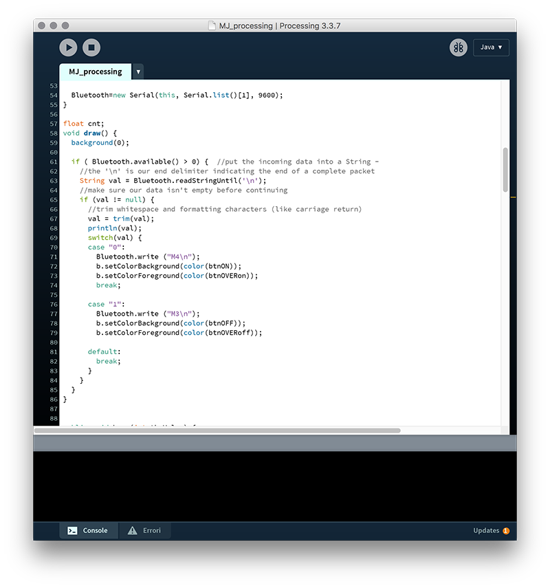
As a first step I made my laptop communicate with the basket of the machine design exercise through Processing. In this case I used the HC-06 module connected to the robot board via an FTDI connector and connected to the RX (receive) and TX (transmission) pins of the microcontroller. using a HC-06 I did not have to set up any master or slave, as it is intrinsic in the properties of the module to be a slave, and then automatically my PC was acting as a master.
So, interfacing with Francesco who wrote the GRBL code for the control of movements for the robot, I inserted the right elements that allowed Processing to send the coordinates to the robot.
According to my final project I had to insert another master that was not only my PC but the remote control that controls the movements of the table.
In this case, a procedure must be followed to set the module as a master or as a slave. With this procedure we can query our HC-06 module to know its address or in what mode it is, whether master or slave.
To do this we can connect the module to an Arduino using a breadboard, download a sketch and load it.
BlueTooth HC-05 Setup #include/*-----( Declare Constants and Pin Numbers )-----*/ #define HC_05_TXD_ARDUINO_RXD 2 #define HC_05_RXD_ARDUINO_TXD 3 #define HC_05_SETUPKEY 4 #define HC_05_PWR1 5 // Connect in parallel to HC-05 VCC #define HC_05_PWR2 6 // Connect in parallel to HC-05 VCC /*-----( Declare objects )-----*/ SoftwareSerial BTSerial(HC_05_TXD_ARDUINO_RXD, HC_05_RXD_ARDUINO_TXD); // RX | TX /*-----( Declare Variables )-----*/ //NONE void setup() /****** SETUP: RUNS ONCE ******/ { pinMode(HC_05_SETUPKEY, OUTPUT); // this pin will pull the HC-05 pin 34 (key pin) HIGH to switch module to AT mode pinMode(HC_05_PWR1, OUTPUT); // Connect in parallel to HC-05 VCC pinMode(HC_05_PWR2, OUTPUT); // Connect in parallel to HC-05 VCC digitalWrite(HC_05_SETUPKEY, HIGH); // Set command mode when powering up Serial.begin(9600); // For the Arduino IDE Serial Monitor Serial.println("YourDuino.com HC-05 Bluetooth Module AT Command Utility V1.02"); Serial.println("Set Serial Monitor to 'Both NL & CR' and '9600 Baud' at bottom right"); Serial.println("Vcc Power Up DELAY"); delay(2000); Serial.println("Applying VCC Power. LED should blink SLOWLY: 2 Seconds ON/OFF"); digitalWrite(HC_05_PWR1, HIGH); // Power VCC digitalWrite(HC_05_PWR2, HIGH); delay(2000); Serial.println("Enter AT commands in top window."); BTSerial.begin(38400); // HC-05 default speed in AT command mode }//--(end setup )--- void loop() /****** LOOP: RUNS CONSTANTLY ******/ { // READ from HC-05 and WRITE to Arduino Serial Monitor if (BTSerial.available()) Serial.write(BTSerial.read()); // READ Arduino Serial Monitor and WRITE to HC-05 if (Serial.available()) BTSerial.write(Serial.read()); }
After loading the sketch, you can open the serial monitor and begin to "ask" the bluetooth module for some information and decide if it will be master or slave. This can be done simply by typing a series of commands directly from the serial monitor.
1 AT Test UART Connection
2 AT+RESET Reset Device
3 AT+VERSION Querry firmware version
4 AT+ORGL Restore settings to Factory Defaults
5 AT+ADDR Query Device Bluetooth Address
6 AT+NAME Query/Set Device Name
7 AT+RNAME Query Remote Bluetooth Device’s Name
8 AT+ROLE Query/Set Device Role
9 AT+CLASS Query/Set Class of Device CoD
10 AT+IAC Query/Set Inquire Access Code
11 AT+INQM Query/Set Inquire Access Mode
12 AT+PSWD Query/Set Pairing Passkey
13 AT+UART Query/Set UART parameter
14 AT+CMODE Query/Set Connection Mode
15 AT+BIND Query/Set Binding Bluetooth Address
16 AT+POLAR Query/Set LED Output Polarity
17 AT+PIO Set/Reset a User I/O pin
18 AT+MPIO Set/Reset multiple User I/O pin
19 AT+MPIO? Query User I/O pin
20 AT+IPSCAN Query/Set Scanning Parameters
21 AT+SNIFF Query/Set SNIFF Energy Savings Parameters
22 AT+SENM Query/Set Security & Encryption Modes
23 AT+RMSAD Delete Authenticated Device from List
24 AT+FSAD Find Device from Authenticated Device List
25 AT+ADCN Query Total Number of Device from Authenticated Device List
26 AT+MRAD Query Most Recently Used Authenticated Device
27 AT+STATE Query Current Status of the Device
28 AT+INIT Initialize SPP Profile
29 AT+INQ Query Nearby Discoverable Devices
30 AT+INQC Cancel Search for Discoverable Devices
31 AT+PAIR Device Pairing
32 AT+LINK Connect to a Remote Device
33 AT+DISC Disconnect from a Remote Device
34 AT+ENSNIFF Enter Energy Saving mode
35 AT+EXSNIFF Exit Energy Saving mode
The steps we need to make to declare whether the module will be master or slave are the following:
1 - AT and the form response will be OK;
2 - AT + cmode = 1 and the answer will be OK again;
3 - AT + role = 1 so as to set the module on which we work as a master (it would have been 0 to set it as slave, to ask how it is currently set, we use the command AT + role?) And the answer that we will still be OK;
4 - AT + init we initialize the search for devices, and the answer will be OK;
5 - AT + inq so as to search for other devices in the vicinity, the answer will be the address of the device found;
6 - AT + bind = (address of the bluetooth to which we connect separated by commas) and we will be answered again OK;
7 - AT + pair = (address of the bluetooth to which we connect separated by commas) we couple the two modules, the answer will then be ok to signal that everything is fine.
This process must be applied to both modules, with the difference that to what we decide to be the slave we must communicate AT + role = 0.
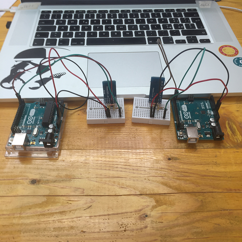
Now I can connect my HC-05 modules to the table (slave) and my HC-06 to the multitouch remote control (master).
Close Project
FINAL RESUL - GROUP PAGE
Mechanical Design
In the laboratory, after a meeting between students and Enrico, we decided to create a machine that has an educational purpose but also a playful one.
We therefore came to the conclusion of creating two small machines with two types of mechanics and two different types of electronics.
The first of these two machines is a spear-ball of which will be responsible for the construction Massimiliano, Laura and Federica. This machine can rotate on a vertical axis and on a horizontal axis thanks to a combination of servo motors and stepper motors.
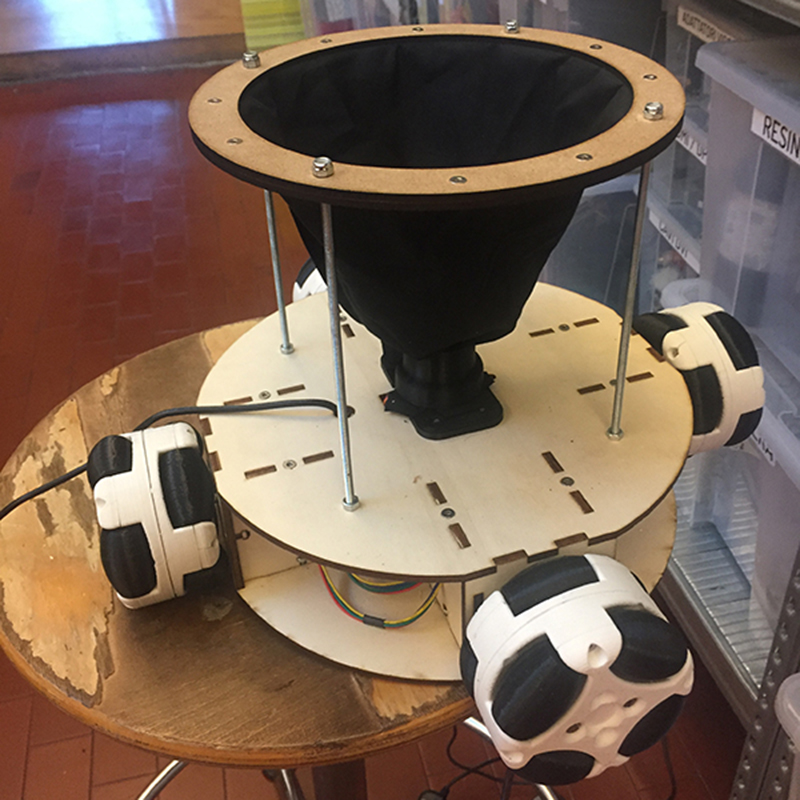
The second machine we decided to make is a target / basket that moves on wheels, which Francesco and I took care of.
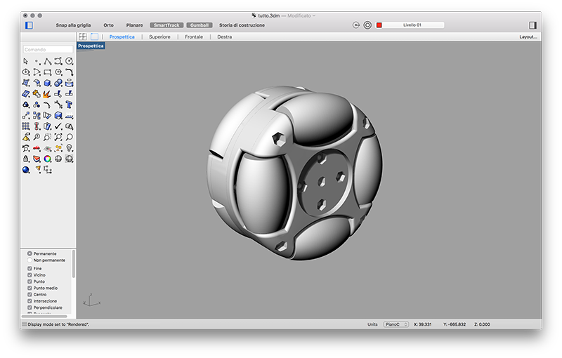
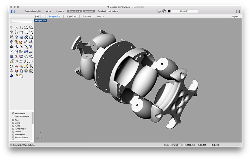
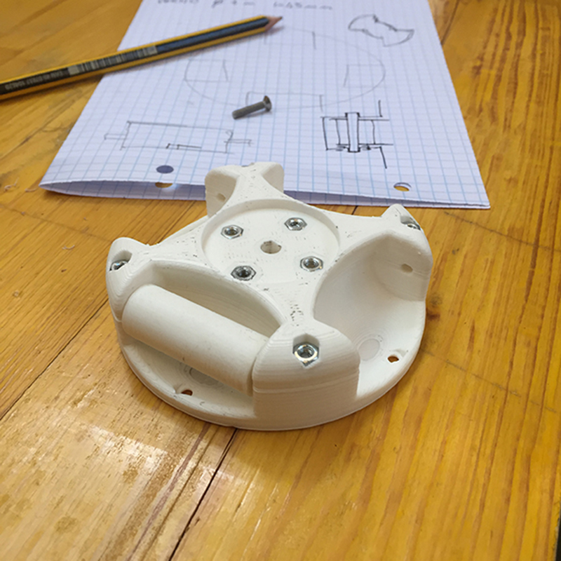
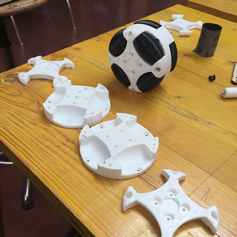
We chose to make a machine composed of a central round body inside which the control board and the motors would be placed, from a basket positioned above the central body and that would move thanks to 4 omniwheels.
We divided the tasks. Francesco took care of the construction of the central body in such a way that it was as low as possible and that it has the right accommodation for the engines and for the board and all the electronic components, while I worked on the wheels and the basket.
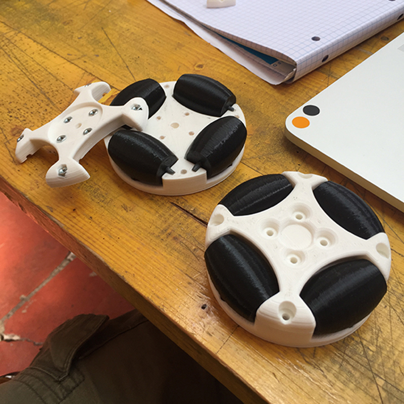
OMNI-WHEELS
Machines and robots that can move in multiple directions are called holonomic.
In short, holonomicity is the relationship between controllable and non-controllable degrees of freedom of a robot.
The degree of freedom is an expression of the type of movement an object can accomplish.
For example, a train will have only one degree of freedom, because it can only move on the axis that binds it to the tracks, forward or backward, while a ball on the plane will have two degrees of freedom (eg xey), plus a third degree if is able to rotate on itself and even a quarter if it can jump in height on the z plane.
If we can control all the degrees of freedom of a robot (or of a vehicle in general), we talk about a holonomic robot, otherwise it will be, with great effort of imagination, non-holonomic.
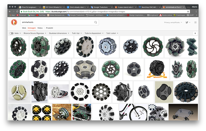
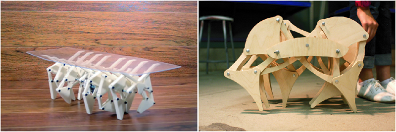
There are different types of wheels that allow this type of movement, including the omni wheels.
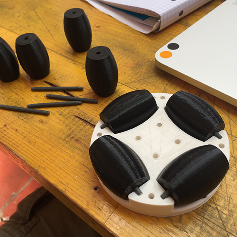
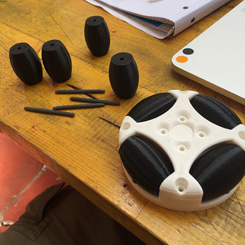
The omni wheels are composed of a central block that acts like any wheel, and two sets of smaller wheels arranged along the diameter and with the axis of rotation perpendicular to that of the central block. With this mechanism, only one wheel can move forward / backward and left / right.
By combining 3 or 4 wheels, different speeds and directions of rotation, a movement of the holonomic machine is obtained.
I started by downloading a wheel model already made by Thingiverse. The model I found was designed for servo motors, so I immediately checked and modified the geometry and the dimensions so that I could make them with the materials present in the laboratory and adapt it to the tolerances of our 3D printer.
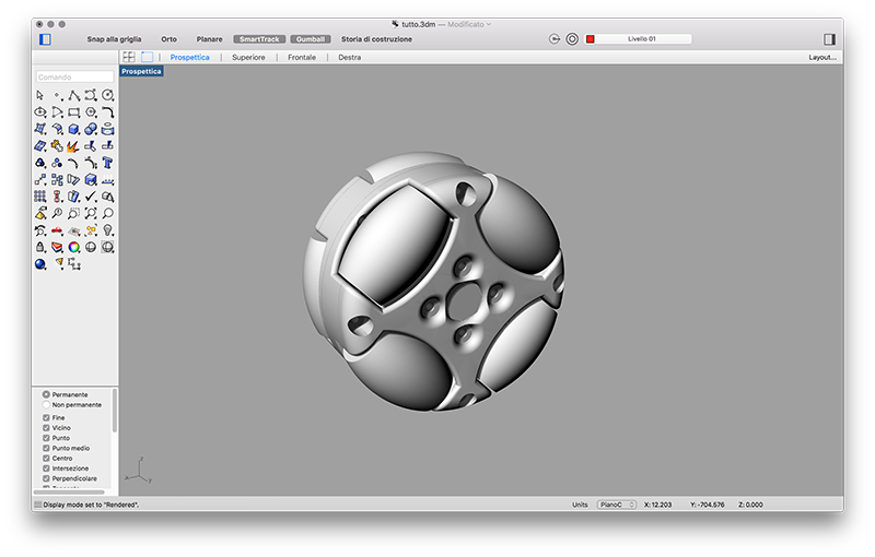
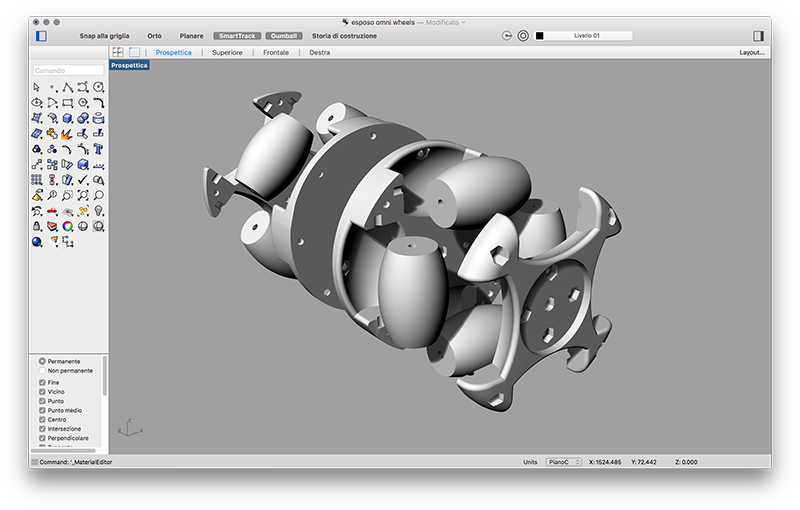
I did several tests for the smaller wheels, but in the end the best strategy was to make them completely with 3D printing. the only thing I did not try to do was the mold. I think I'll try for the final project.
I left the smaller wheels free to turn on themselves, trying to block them as little as possible to facilitate their task.
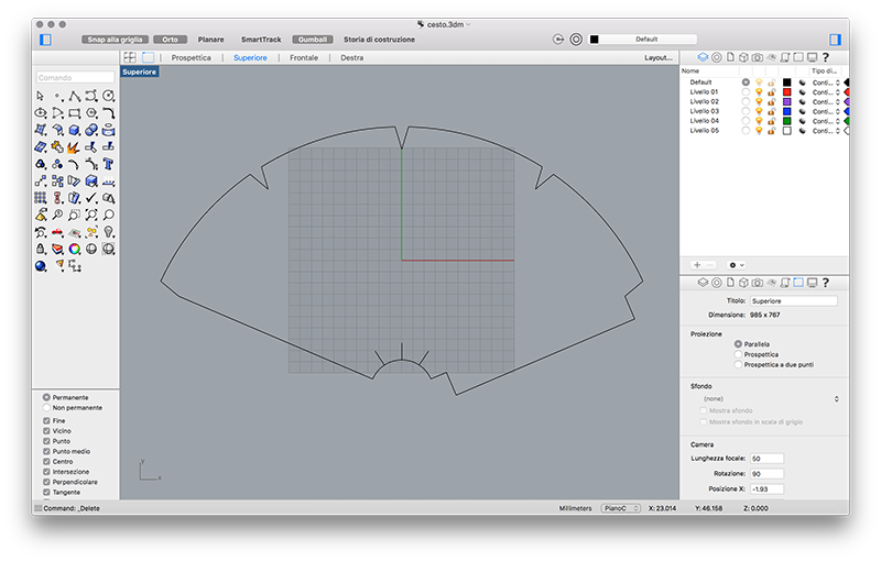
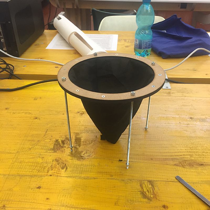
Making the basket was quite simple.
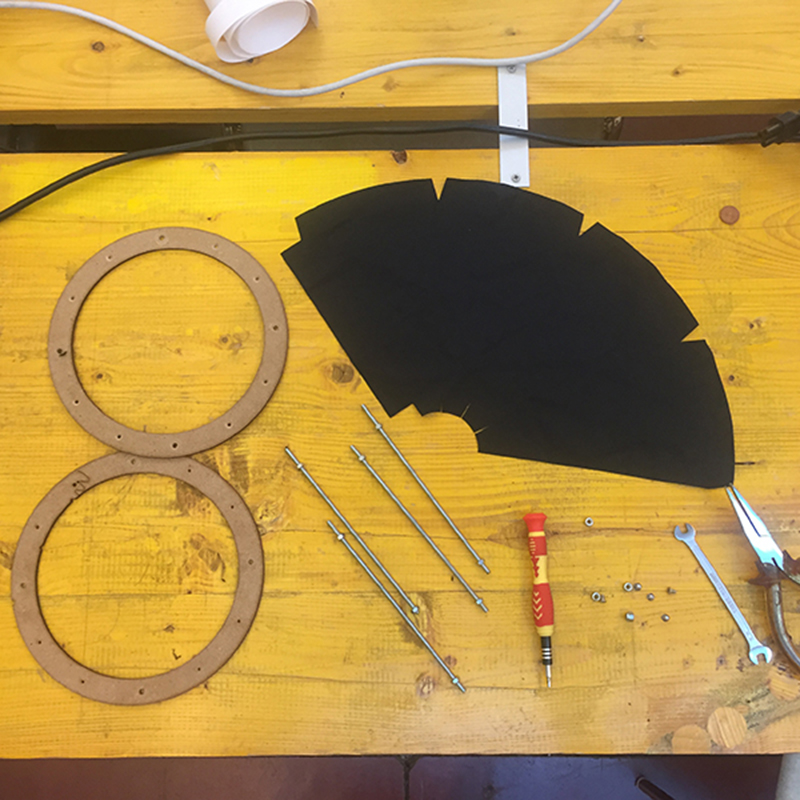
All I had to do was develop a cone flat so that it had a big enough hole at the bottom to push the ping pong ball through. Then I added some flaps to sew the two flaps and to fix it to the upper and lower rings.
Finally I placed the fabric in the lasercut, I set a very fast laser displacement speed (70) and the maximum power (100).
The cut came precise and above all did not catch fire.
 Close Project
FINAL RESUL - GROUP PAGE
Machine Design
To realize the basket interface I used three different examples of the ControlP5 package.
For the FEEDRATE
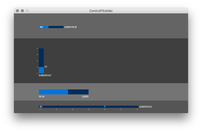
For the BANG

For the POSITION
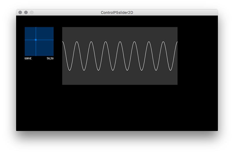
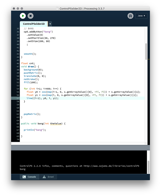
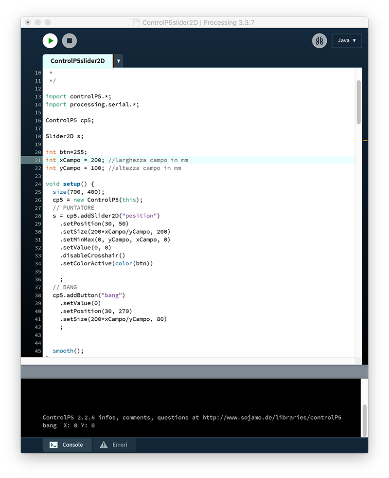
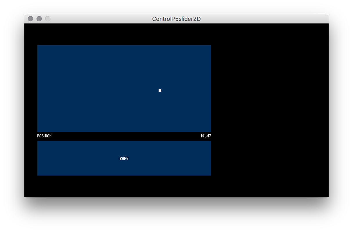
As a basis I started from the example "Slider2D" by deleting the sinusoidal curve and the cross following the pointer. This element will be used as a field of action of the robot. The field size can be decided before starting the interface, and the rectangle that defines the field of action is resized in proportion to the measures entered.
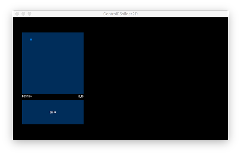
I added the button from the example "Button" and placed it under the field rectangle. The button also adapts to the width of the field. To make the interface more user frendly I have made sure that every time the mouse pointer passes over the button changes color when the button is pressed changes color again.
Then, above the range rectangle, I inserted a sliderticks from the example "ControlP5Slider". Also this slider has a fixed height but the width follows that of the rectangle like the button.
I also changed the number and value of the feedrate notches, dividing it into five speeds between 0 and 1000.
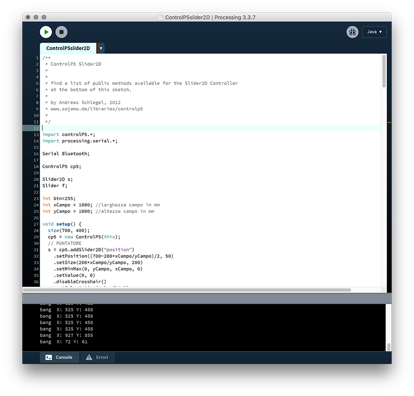
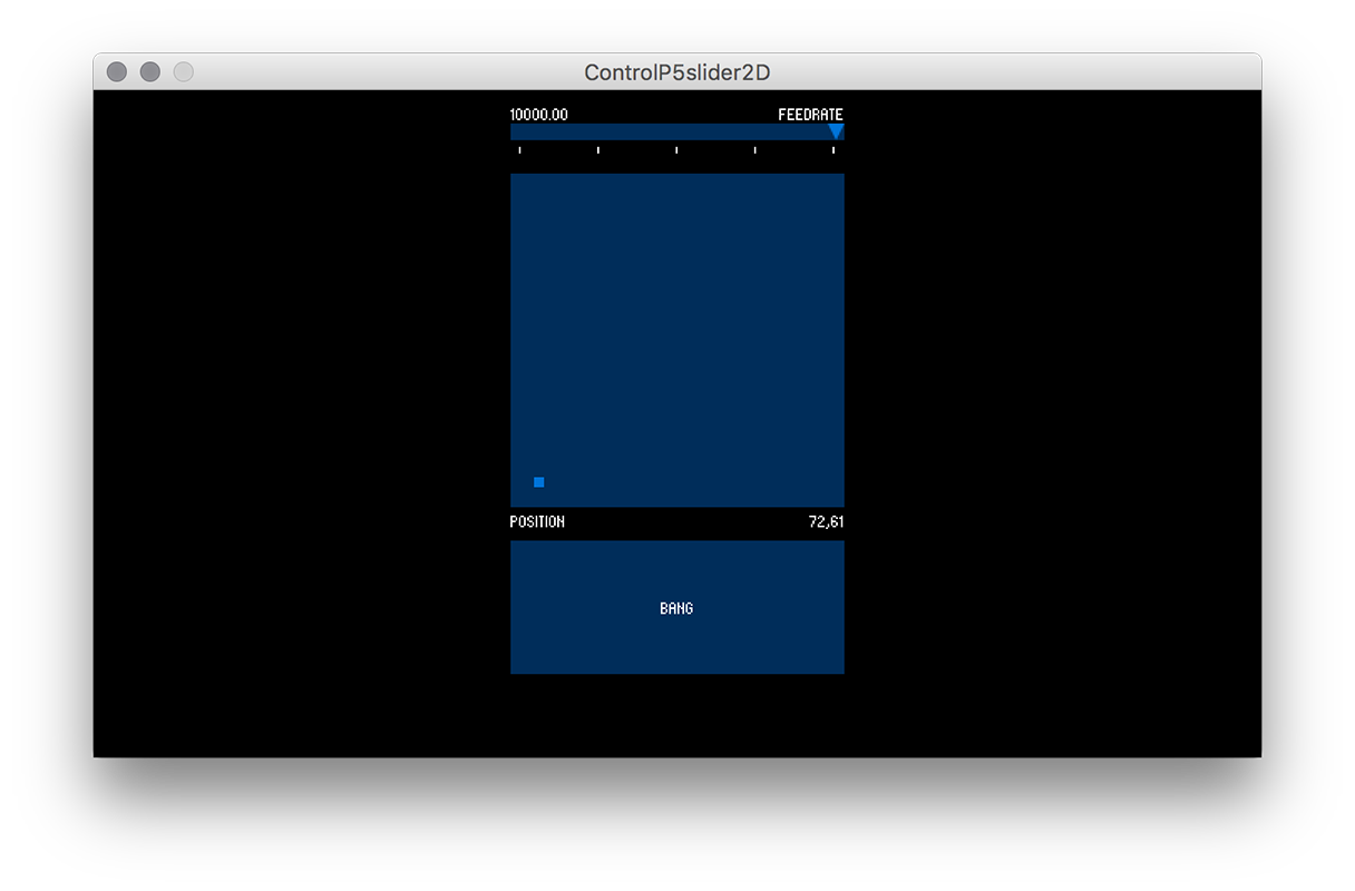
To complete the graphic part of the interface, I have made sure that all the elements are always in the middle of the dialog, and that when the width of the playing field changes, all the elements (feedrate, field and button) are widened both to the right that left.
In the robot we made we placed an infrared sensor on the bottom of the basket to detect the ball that reached the target. To communicate that the ball has hit the basket, the launch button "BANG" changes color and turns red.
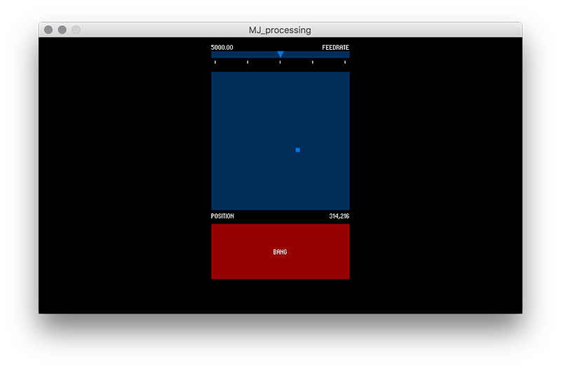
Finally I made sure that Processing communicated with the board created by Francesco via bluetooth..
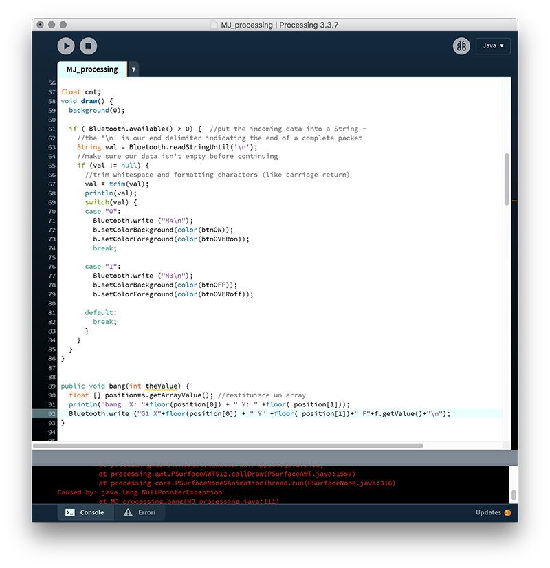
                import controlP5.*;
import processing.serial.*;

Serial Bluetooth;

ControlP5 cp5;

Slider2D s;
Slider f;
Button b;

int btn=255;
int btnON=color (255, 0, 0);
int btnOFF=color (9, 46, 92);
int btnOVERoff=color (150, 0, 0);
int btnOVERon=color (16, 111, 179);
int xCampo = 1000; //larghezza campo in mm
int yCampo = 1000; //altezza campo in mm

void setup() {
  size(700, 400);
  cp5 = new ControlP5(this);
  // PUNTATORE
  s = cp5.addSlider2D("position")
    .setPosition((700-200*xCampo/yCampo)/2, 50)
    .setSize(200*xCampo/yCampo, 200)
    .setMinMax(0, yCampo, xCampo, 0)
    .setValue(0, 0)
    .disableCrosshair()
    .setColorActive(color(btn))

    ;
  // BANG
  b = cp5.addButton("bang")
    .setValue(0)
    .setPosition((700-200*xCampo/yCampo)/2, 270)
    .setSize(200*xCampo/yCampo, 80)
    ;


  smooth();

  f = cp5.addSlider("feedrate")
  .setPosition((700-200*xCampo/yCampo)/2, 20)
  .setRange(0, 10000)
  .setSize(200*xCampo/yCampo, 10)
  .setNumberOfTickMarks(5)
  .setSliderMode(Slider.FLEXIBLE)
  ;

  cp5.getController("feedrate").getValueLabel().align(ControlP5.LEFT, ControlP5.BOTTOM_OUTSIDE).setPaddingX(0) .setPaddingY(-20);
  cp5.getController("feedrate").getCaptionLabel().align(ControlP5.RIGHT, ControlP5.BOTTOM_OUTSIDE).setPaddingX(0) .setPaddingY(-20);

  Bluetooth=new Serial(this, Serial.list()[1], 115200);
}

float cnt;
void draw() {
  background(0);

  if ( Bluetooth.available() > 0) {  //put the incoming data into a String -
    //the '\n' is our end delimiter indicating the end of a complete packet
    String val = Bluetooth.readStringUntil('\n');
    //make sure our data isn't empty before continuing
    if (val != null) {
      //trim whitespace and formatting characters (like carriage return)
      val = trim(val);
      println(val);
      switch(val) {
      case "0":
        Bluetooth.write ("M4\n");
        b.setColorBackground(color(btnON));
        b.setColorForeground(color(btnOVERon));
        break;

      case "1":
        Bluetooth.write ("M3\n");
        b.setColorBackground(color(btnOFF));
        b.setColorForeground(color(btnOVERoff));

      default:
        break;
      }
    }
  }
}


public void bang(int theValue) {
  float [] position=s.getArrayValue(); //restituisce un array
  println("bang  X: "+floor(position[0]) + " Y: " +floor( position[1]));
  //Bluetooth.write ("x100"+floor(position[0]) + " Y" +floor( position[1])+" F"+f.getValue()+"\n");
  //Bluetooth.write ("y100"+floor(position[0]) + " Y" +floor( position[1])+" F"+f.getValue()+"\n");
  //Bluetooth.write ("w100"+floor(position[0]) + " Y" +floor( position[1])+" F"+f.getValue()+"\n");

  Bluetooth.write ("x100\n");
  Bluetooth.write ("y100\n");
  Bluetooth.write ("w100\n");
}
Close Project
For the week of wild cards we decided to test a CNC machine applied to the world of fabrics and embroidery. This type of machinery is more widespread in the industrial sector, in medium-large structures, so there are few numerical control machines that embroider and that can be transported or kept in a FabLab. This is also evident from the software that has been developed, which are just as few, cumbersome and not very intuitive to use.
Thanks to Laura Cipriani, one of the creators of "La Bottega Dei Dotti" we have been able to deepen this type of CNC machines.
The software we used for file processing is PE-DESIGN 10.
The file I used was made with Illustrator, but for some strange reason PE-DESIGN can only import .png files.
After importing the .png file, you have to re-vectorize and clean the drawing.
Finishing the file preparation proceeds with the assignment of the workings.
You can choose between lines and fills.
The lines can be of various types (zig-zag, linear) and you can control the thickness and density of the points.
Fills have more parameters. In addition to the density of the points you can decide the orientation of the paths and which plot to assign them.
Before processing images on PE-DESIGN, you must prepare the vector image on DESIGN CENTER.
You can import both a vector image and a raster image. To extend the documentation I started from a .png file.
After embossing the image you have to make some steps to extract the outlines in vector form.
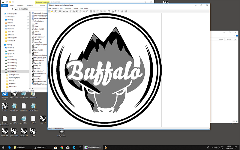
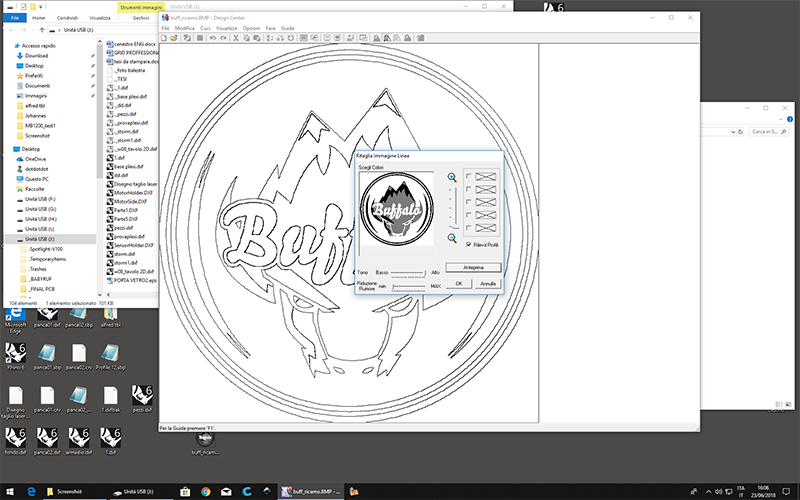
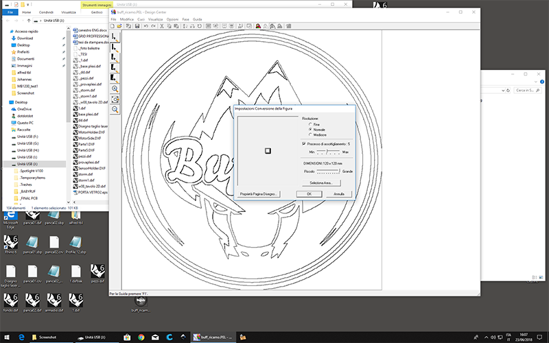
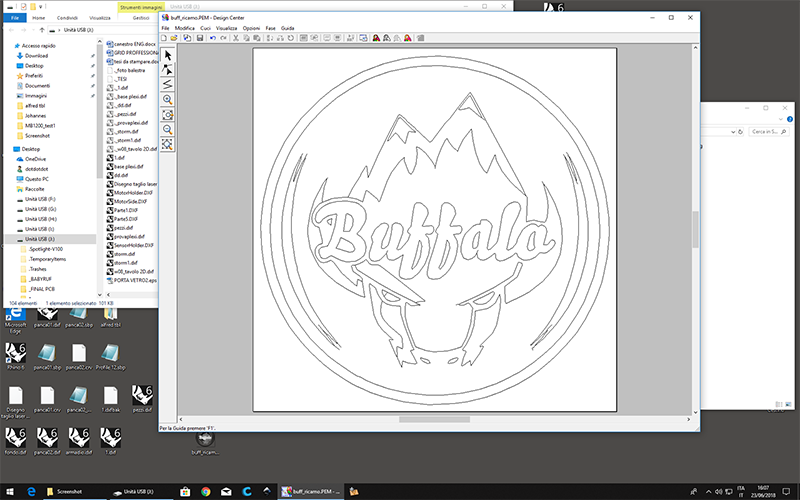
Now you can go to the section where the various types of processing are assigned. You can also assign different colors to which they can reflect the colors of the threads that will be used in reality. This serves to pause the machine at the end of each processing.
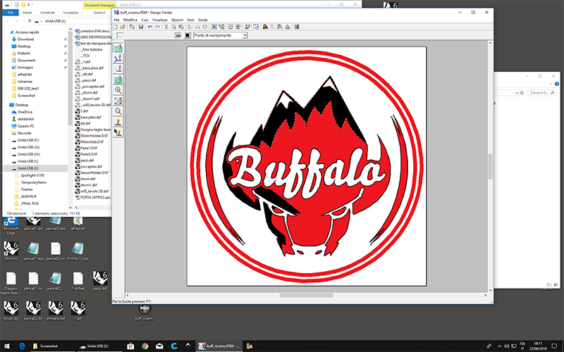
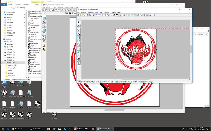
The processes can be of two different types: lines and fills that can be compared, for example, to the vector and raster workings of the lasercut.
Each type of processing can be assigned different textures or types of points. For example, for the two contour circles I have assigned a zig-zag line, in this way it is processed as if it were a thicker line and the needle goes continuously from left to right. For the fills instead I opted for a 45 ° filling.
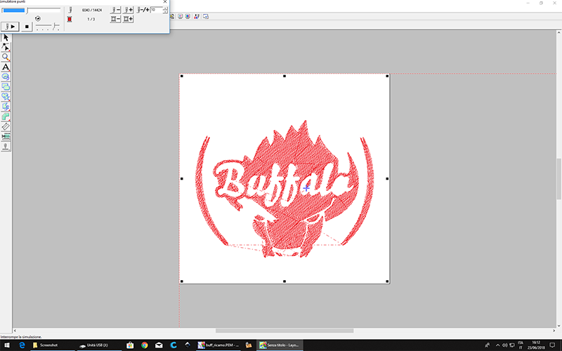
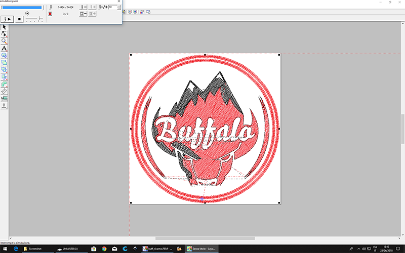
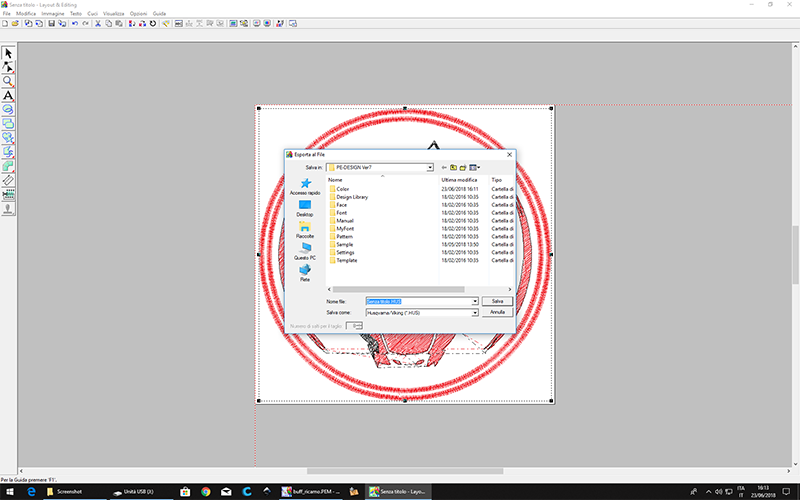
After assigning the operations, you save the file and import it on PE-DESIGN.
Here we just have to place the complete processing on the frame and export the file that will be read by the embroiderer.
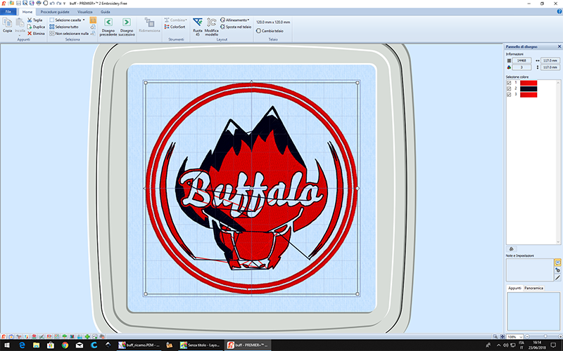
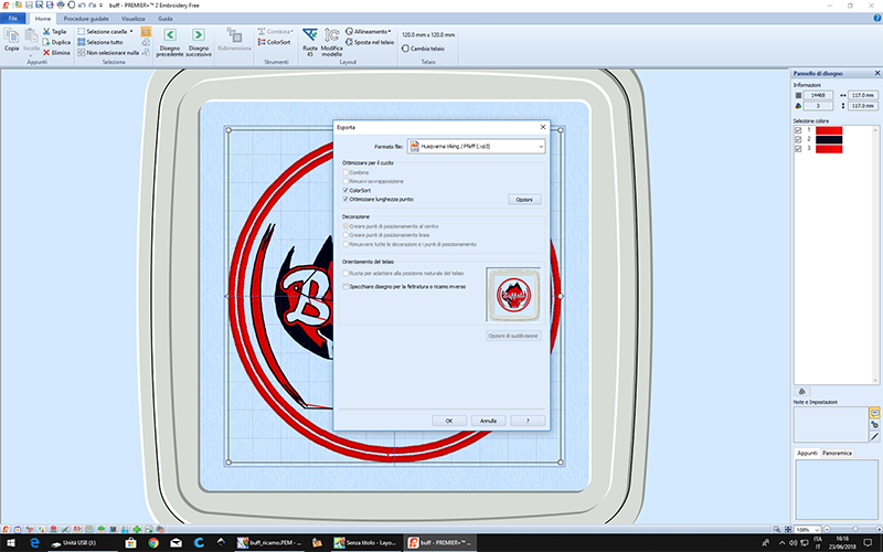
To make the Embroidery we used a Husqvarna DESIGNER TOPAZ 30. It can be used both for sewing in the traditional way and for making numerical control embroidery. Included are two different frame sizes: 120x120mm and 200x360mm, and unfortunately you can only load one thread color at a time.

The machine does not need to be set in particular ways for CNC machining, since everything has already been set in the software.
To get a good result the fabric must be positioned at its best, orientating the weft and the warp well. Furthermore, the fabric must be strengthened using 2 or more layers depending on the thickness of the fabric.
The only necessary control we need is the speed of processing. We can adjust the speed easily during the process.

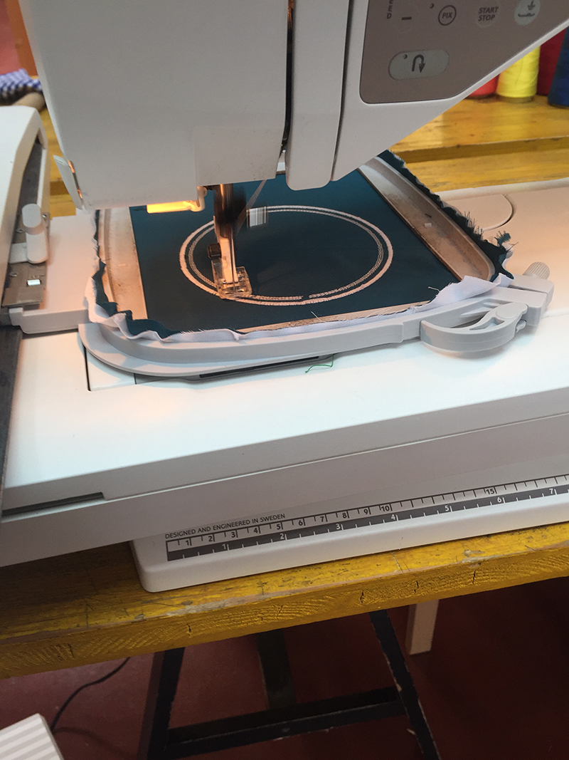
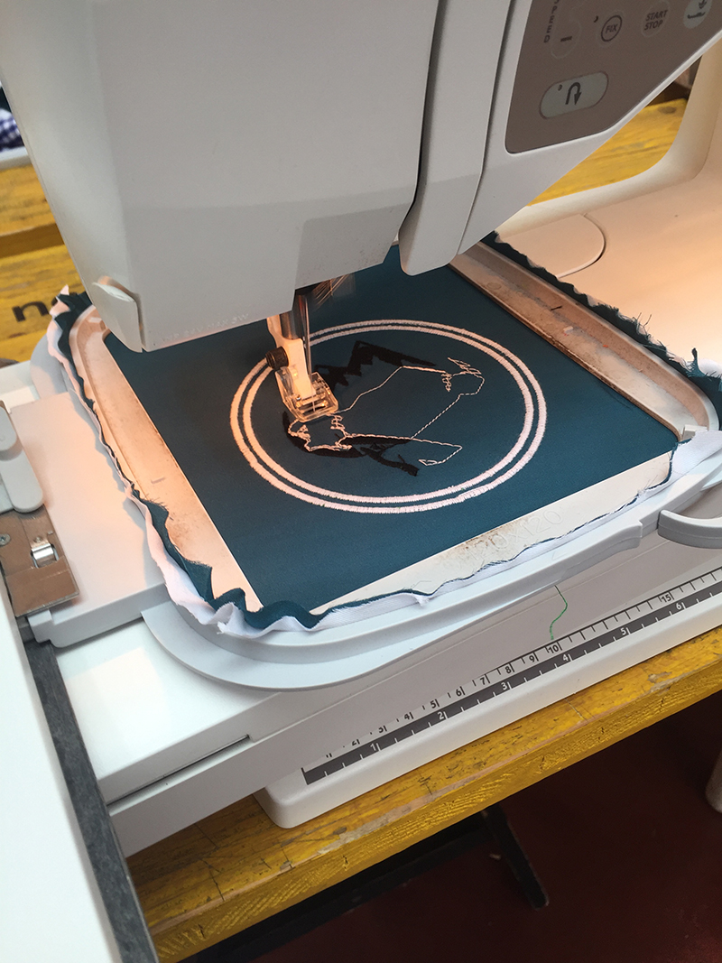
It may happen that the thread ends on the lower reel. In this case the machine stops the processing a little before the wire runs out, so that we can change it in all tranquility and resume processing from where it was interrupted.
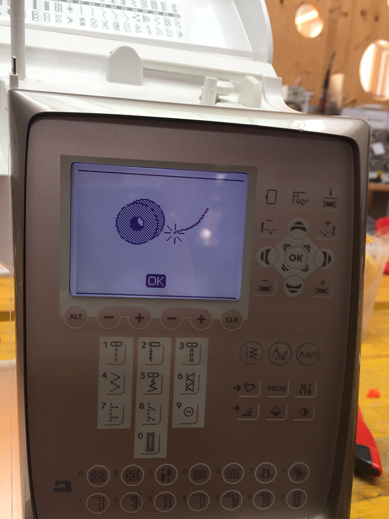
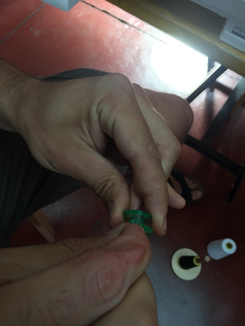
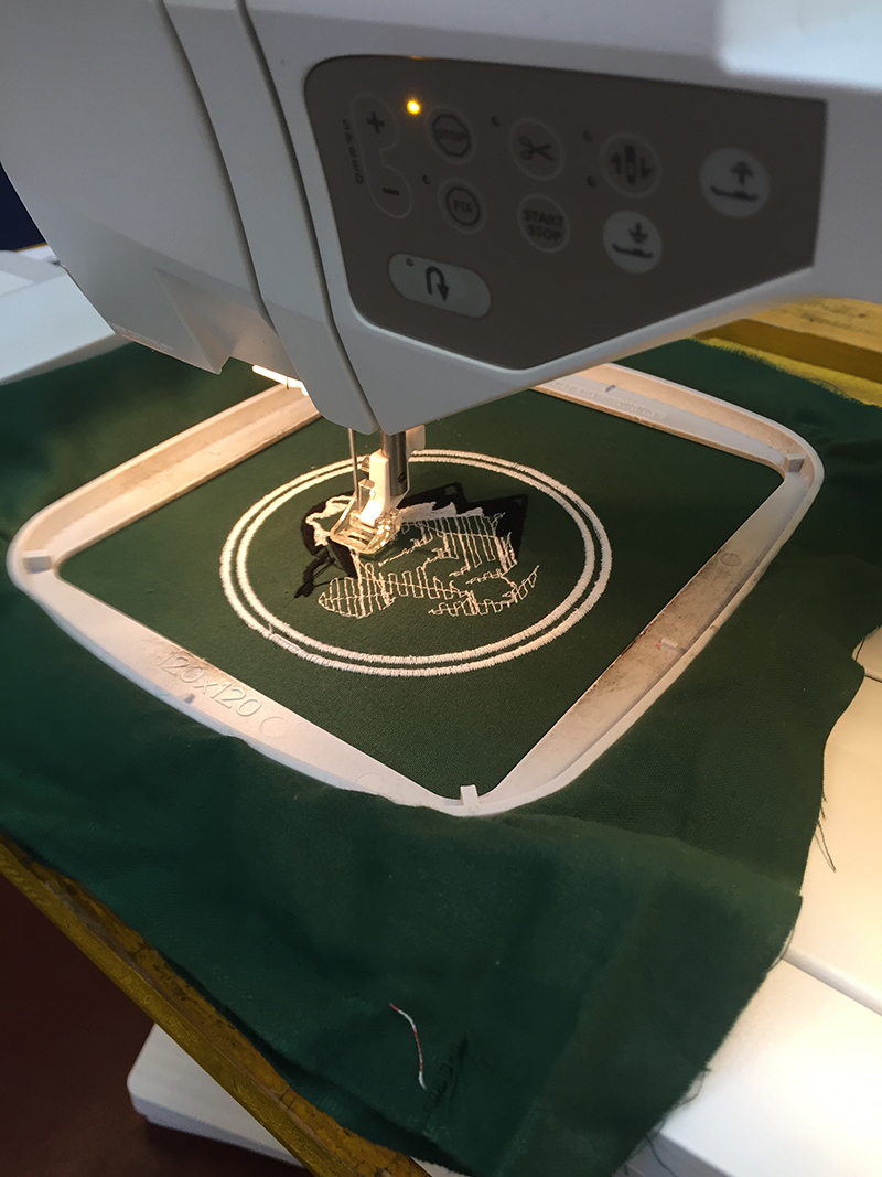
Naturally, a good result could not have come at the first attempt.
I made the mistake of not tending the fabric well, in fact the final processing from a certain point on has come slightly moved.
 Close Project
WHAT WILL IT DO?
The final project consists of a coffee table that can be moved thanks to a remote control. The dimensions will be more or less 40x40x60 cm. The table can be moved thanks to 3 or 4 omni wheels controlled by a stepper motor each. Thanks to the omniwheels, the table can be moved in any direction.
The remote control will have 16 capacitive keys (which can become 32 if you place the finger astride two keys) arranged in a circle and will communicate in bluetooth with the table.
Initially I wanted to create a small work table able to follow the operator bringing all the necessary tools, keeping a safe distance from both the operator and the obstacles that may exist in a laboratory.
I was inspired by mixing several projects of objects that move in control. There are many examples of objects that move on wheels with numerical control, ranging from vacuum cleaners to milling machines, passing from simple robots with distance sensors to avoid going against other objects.
WHAT HAS BEEN DONE BEFORE?
Here are some examples:
• Robot
• Suitcase
• Things that move
• Milling machine
• Vacuum cleaner
WHAT MATERIALS AND COMPONENTS WILL BE USED?
• Plywood - 14 €/mq
• Plexiglass 4mm - 33,60 €/mq
• ATmega 88 - 2,07€
• Stepper motor - 20€
• HC-06 - 8,49€
• Stepper driver - 8,95€
• Pcb
• Smd components
• PLA
HOW WILL IT BE REALIZED?
Body: The supporting structure of the table will be entirely in plywood. The project will be done with Rhinoceros, processed with V-Carve, which will be milled with the CNC.
The wheels will be made with two different techniques. The main body of the wheels (I have yet to choose the best method) will be done either with 3D printing or using laser cutting. While the wheels that allow the transverse movement will be injection molded.
Board: The board for controlling the table and the remote control will be designed with AutoDesk Eagle and milled with the Rolad milling machine.
Program: if the table has four wheels, a specially modified GRBL will be used. While if the wheels were to be three, a program will be written from scratch.
Interface: the interface will be useful to control the table even from a PC or smartphone.
WHAT QUESTION NEED TO BE ANSWERED?
Are the wheels able to hold the weight of the structure?
Will it be easy to command it while not being able to turn on itself?
Will it be able to move on different types of flooring?
HOW WILL EVALUATED?
I hope my project is seen as a work-in-progress. As I said at the beginning, I would like to make a workbench that is functional in a laboratory or a workshop.
So let's say that, in 6 months of FabAcademy, this seems like a good start.
PLAN

.. would have been very nice to respect the program done. But in reality it went like this:
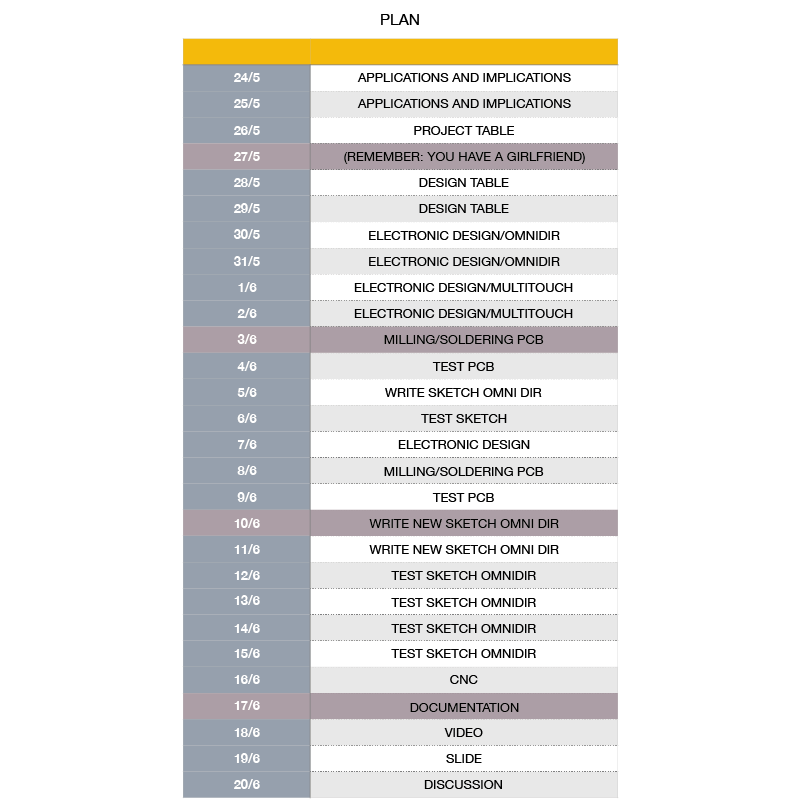 Close Project
Since the base of the project, that is a robot that moves thanks to stepper motor and 3 omni wheels, has already been treated by many people, and from which I copied and modified thanks to the philosophy of open source, it seems correct to reciprocate.
So I decided to apply an the Creative Commons (CC BY 3.0 IT) license to my table. In this way it can be continuously developed, as it happened before I started this project.
 Close Project
• What tasks have been completed, and what tasks remain?
To my great joy I managed to conclude the main parts of my project. the interlocking wooden structure without the use of glues or screws, the realization of the wheels with the 3D printer, the creation of the board and the writing of the code for the movement of the table.
Unfortunately, this last task took me a lot of time, so I could not finish the realization and programming of the remote to control the table via bluetooth.
• What has worked? what hasn't?
I would not have expected it, but the code worked well!
Even the structure of the birch plywood table was not too heavy for the mototri.
The parts that are to be improved instead are the wheels. In fact the smaller wheels that allow the transverse movement are smooth and completely molded with the PLA, therefore they did not grip the ground. There are two solutions to try: one is to maintain the technique of 3D printing and make grooves along the circumference, or to cover the small wheels with a rubbery material (but not too soft).
• What questions need to be resolved?
Since it was designed to have different uses, my doubts are different:
- How many types of wheels do you have to design?
- How many types of board do you have to design?
- What kind of engines will be needed?
• What will happen when?
I hope it will become something useful, both for me and for those who will have to use it.
• What have you learned?
Coming from the world of design and never having approached electronics, I learned that when there is a problem, do everything to solve it, and after having arranged it always happens another.
Joking aside, I learned how to approach electronics, searching for and crossing the information coming from my colleagues / comrades and the internet, and joining them all together to create something that is tailored to my project.


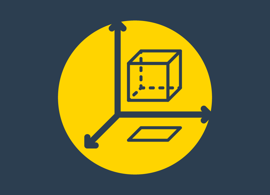

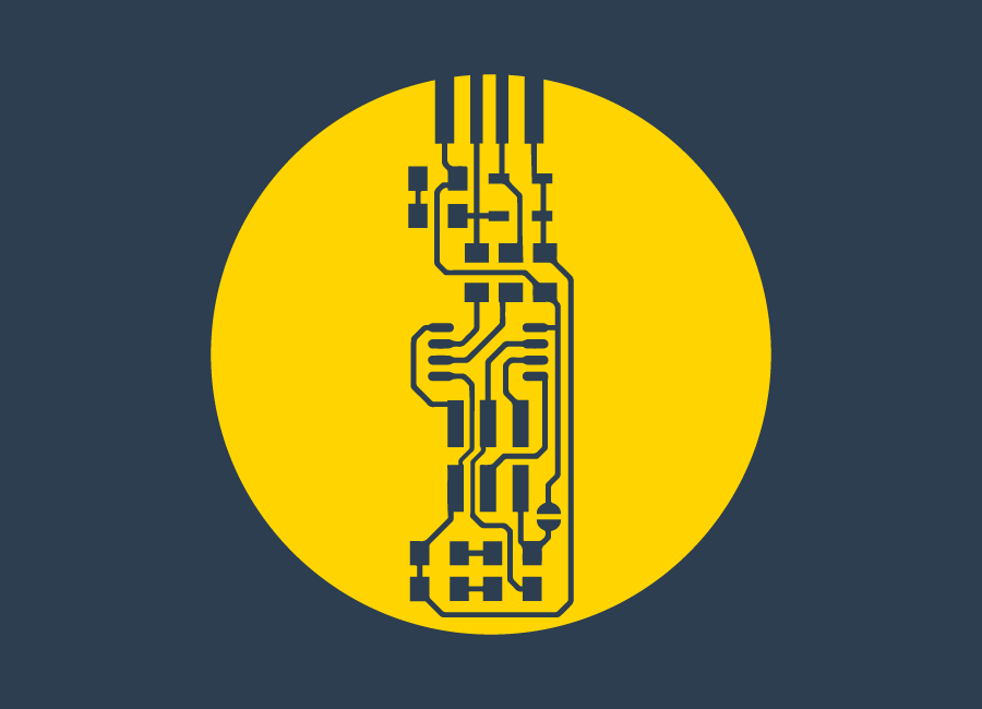
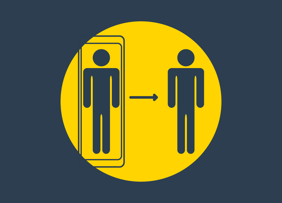


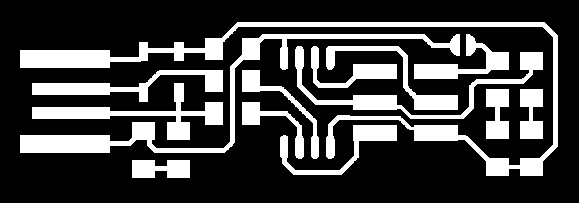
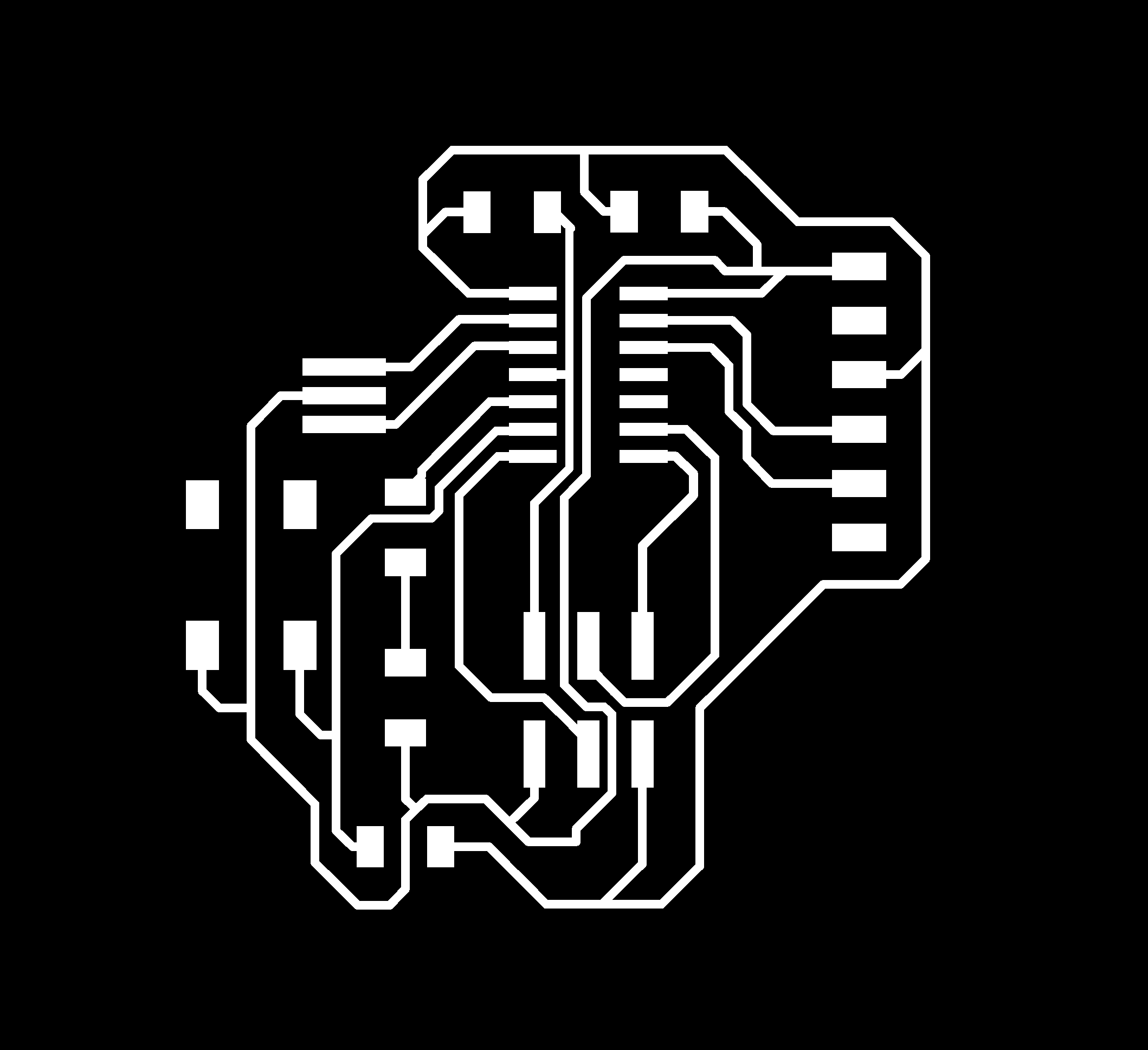