Week14
Networking and Communications
I2C, serial and SPI
Assignment:
Send a message between two projects
You can see the complete documentation of group assignments on the opendot website at this LINK.
Intro
Before starting this exercise I needed to reread and deepen the different communication protocols, at least of the Arduino since it mounts the same microcontroller of my board, at least to understand what kind of possibility I had. I save here some basic resource so as not to forget the other protocols we have seen in class.
SERIAL
SPI
I2C
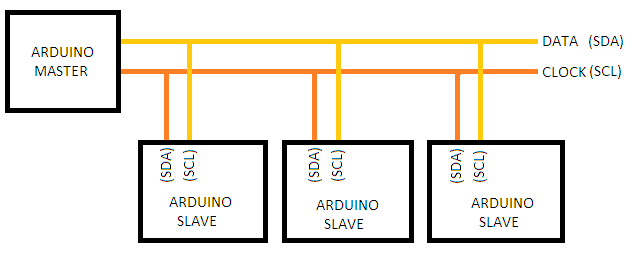
Start with I2C
I decided to start with the i2c protocol because it will be the one with which my board will communicate with that of Francesco during the final project.
This will make it possible to lock the drawer only to users enabled via RFID.
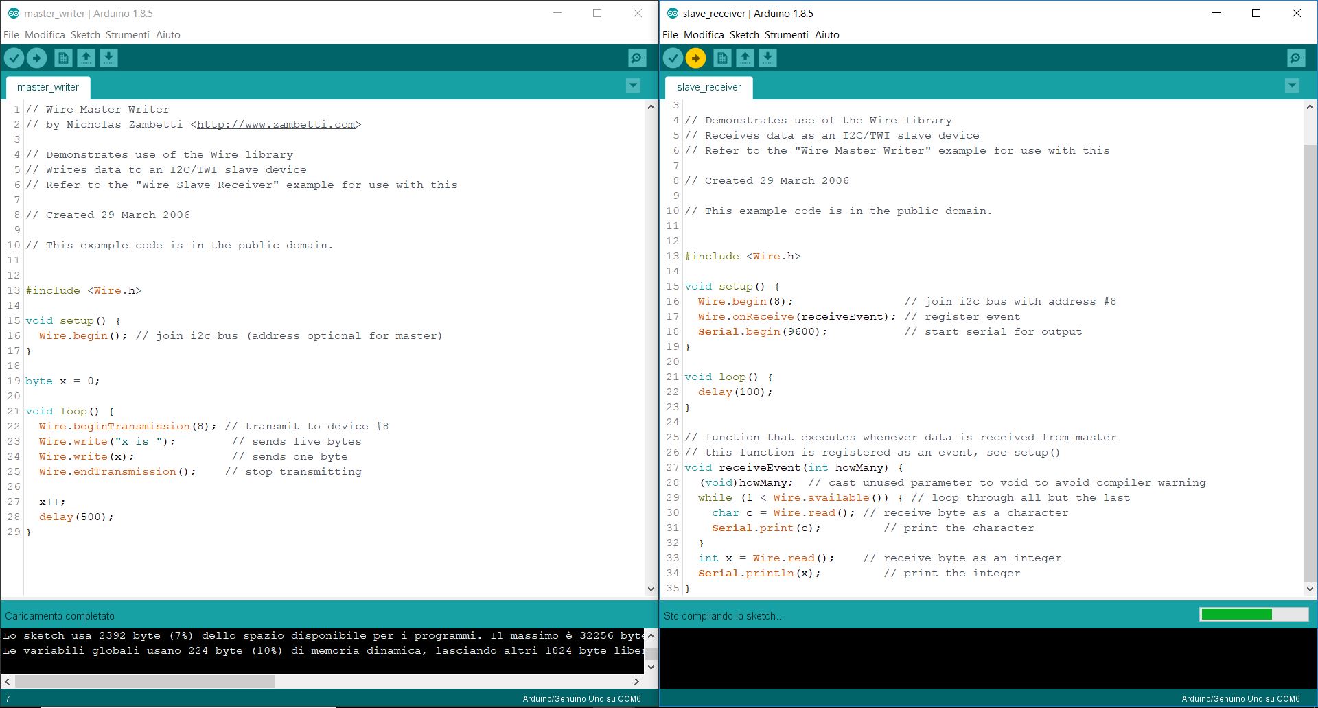
To understand the protocol, during the lesson I started with a very easy setup and examples, I used an Arduino UNO as a master and an Arduino Nano as a slave.
I try to connect my board as a master and ad arduino as a Slave, upload an example code from the library but apparently nothing happens.
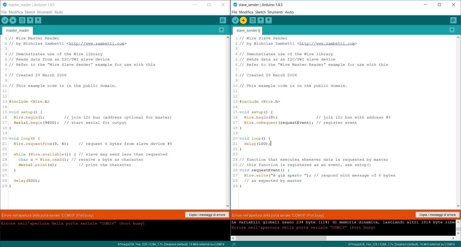
I try to connect my board as a slave(sender) and ad arduino as a master(reader), upload an example code from the library but now I can not open the serial monitor.. Then I understand that in this case is better to start with a specific code for my project. The idea behind this is that my board would work as a receiver and move the servo accordingly.
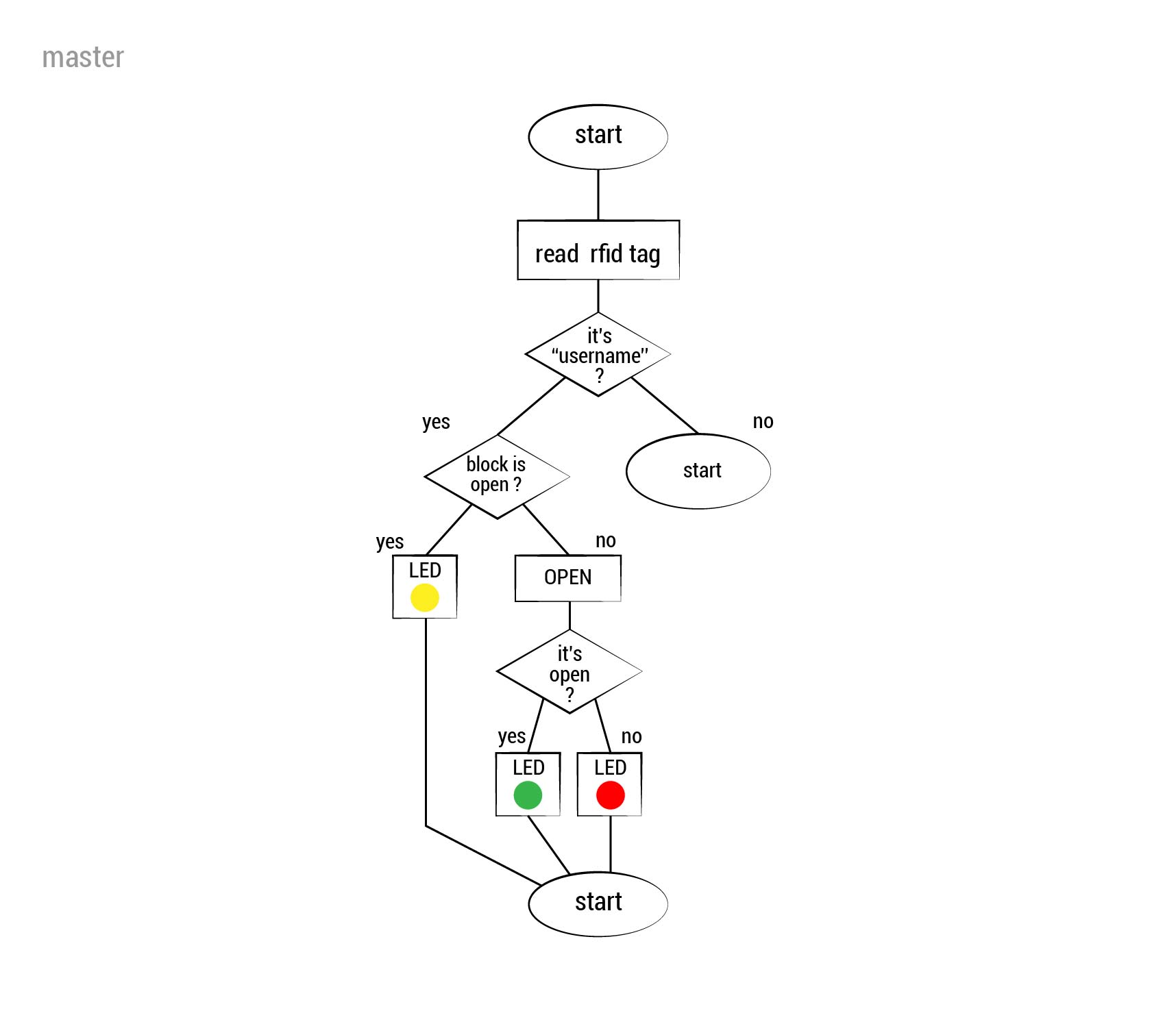
Work on Final project code: Francesco's board as Master
The board of Francesco will do as a master. This is his scheme, at this LINK all the material.
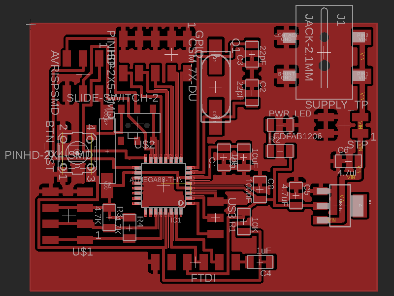
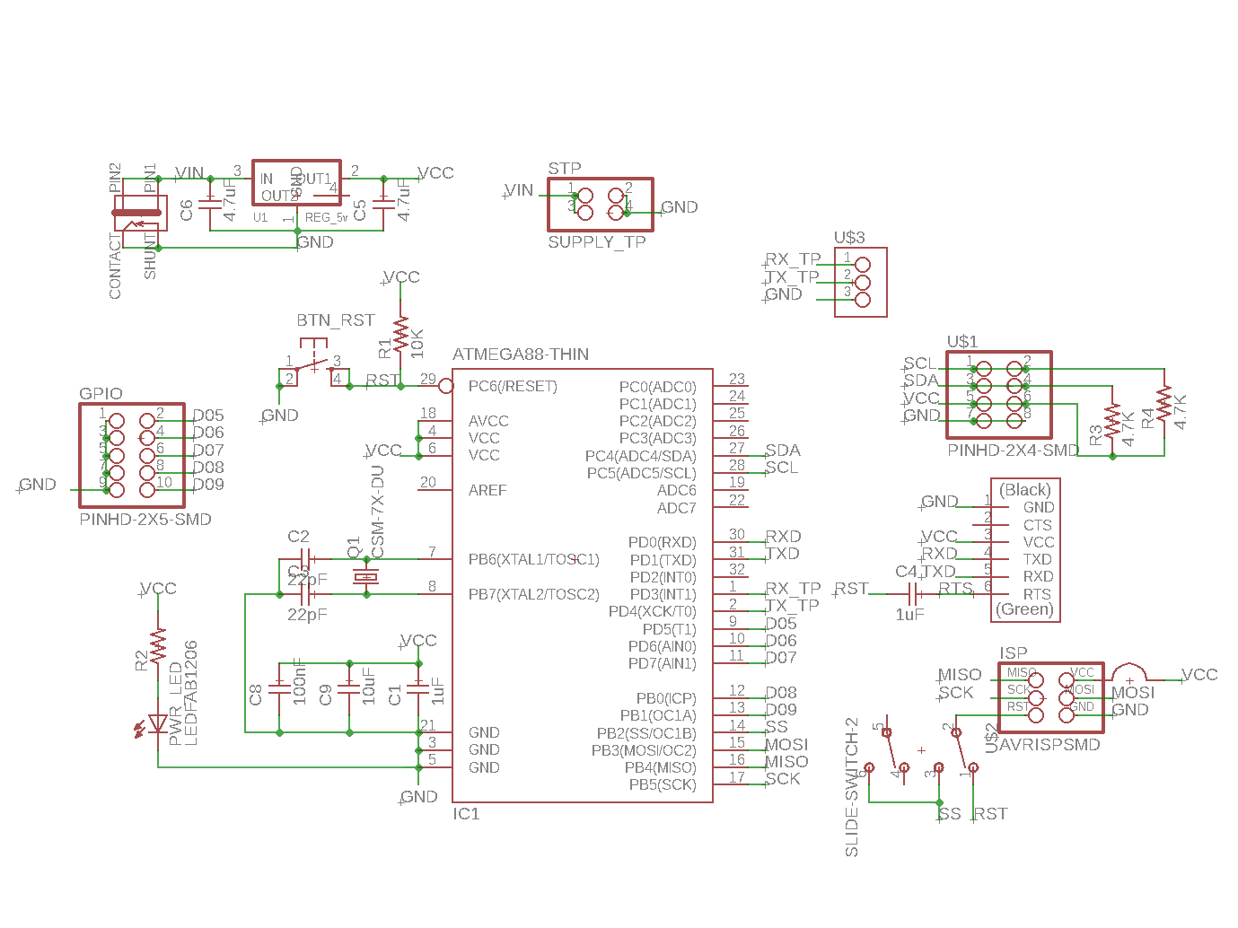
Work on Final project code: my board as a slave
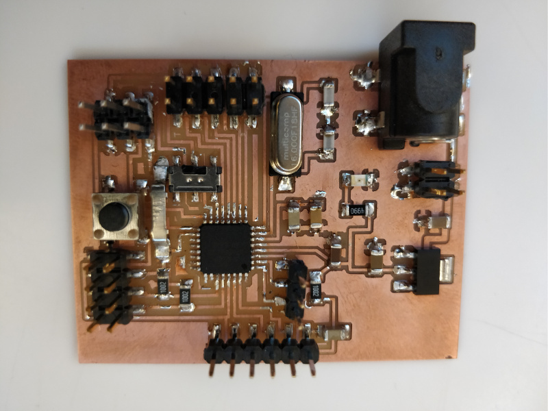
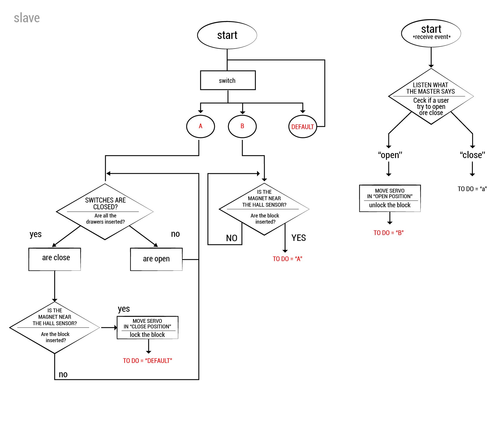
I started writing the code of the final project and, with FRANCESCO , we defined the flow chart, necessary for communication. We start by designing the flow chart of both codes. I work with my FINAL PROJECT BOARD, documented HERE .

Within the final project my board will be fed through that of francesco.
We started to monitor the code by inserting a "serial print" function for monitoring.
Later we tried to communicate "open" to my board when the RFID is passed over the reader.
The interaction consists of:
the master asks for a bit (is it open?)
My board answers FALSE (so it's closed) but in theory it should be open.
In our simulation switches are always closed to simplify switches. In reality, the closed switches correspond to the insertion of the drawers.
The first time we read the hall the sensor does not move so we will need to set a range within which the reading will take place.
NO HALL: 512 (analog read)
hall +/- 512 = sensor insert, so we use ABS
communication i2c from lauracip on Vimeo.
//code for slave: for open and closed drawers with a master board #include//for i2c #include #define drawer_pin 5 //digital input metti il numero del pin #define servo_pin 10 //pwm servo pin #define lock_pin A0 //analog input pin hall sensor #define address_i2c 8 //address bus #define lockthreshold 20 //hall sensor analogue reading threshold #define closepos 20 //servo position closing (block inserted) #define openpos 160 //posizione servo opening (block not inserted) Servo moveLock; // create servo object to control a servo char todo = 'a'; void setup() { Wire.begin(address_i2c); // join i2c bus with address #8 Wire.onReceive(receiveEvent); // register event Wire.onRequest (requestEvent); Serial.begin(115200); // start serial for output Serial.println("Start..."); pinMode (drawer_pin, INPUT); //drawer pin (switch digital input) moveLock.attach(servo_pin); // attaches the servo on pin 10 to the servo object if (drawer() && isLock()) { //initial check to see if it is closed closed(); //move servo motor } else { opened(); //move servo motor todo = 'a'; } } void loop() { switch (todo) { case 'a': //drawer is open and must be closed if (drawer ()) { if (isLock ()) { closed(); todo = '0'; // nothing } } break; case 'b': //The drawer has just opened because the master has told him to do it. and must not close up if ( isLock() == false ) { //do it if the block has been removed todo = 'a'; //make sure that you check whether it should close or not } break; default: break; } delay(100); } //he does it when something is sent to him from the master void receiveEvent(int howMany) { String cmd = ""; //buffer while (Wire.available()) { //if there is at least one byte to read he performs. - 0 lockthreshold); //the more I'm getting closer, the more it increases } //turn servo motor to close void closed () { moveLock.write(closepos); Serial.println("closed"); //write on the serial when it's closing, useful for verification } //turn servo motor to open void opened() { moveLock.write(openpos); Serial.println("opened"); //write on the serial when it's opening, useful for verification } //It's open? if is open: true, if is closed: false bool isOpen () { return (moveLock.read() == openpos);